| Previous Tutorial | Tutorial 29 | Next Tutorial | |||||
| Interfacing Accelerometer/Gyro (MPU6050 IMU) With PIC MCUs | |||||||
| Intermediate Level ★★★☆☆ | |||||||
In this tutorial, we’ll discuss how to interface MPU6050 IMU (Accelerometer + Gyroscope) with PIC microcontrollers. And we’ll write a C code driver to get raw data from the sensor with both PIC18F2550 & PIC16F877A. You’ll also know the internal structure of the MPU6050, its register map, and how to configure each part of it. So you can change the data rate/sampling or the scale for each of the accelerometer and gyroscope.
This considerably long article includes all the information you’ll need to get a very good understanding of how to interface the MPU6050 IMU. And to configure it to suit your application and more importantly write your own library from scratch and get raw & converter data. So you can replicate Arduino projects or hopefully implement your own new ideas!
This tutorial includes 3 practical LABs, the last of which will be a speed controller stick using MPU6050 accelerometer. Here is a short demo video for this LAB, you’ll be able to make this as well by the end of this article!
without further ado, let’s get started!
[toc]
Needed Components For This Tutorial
| Qty. | Component Name | Buy On Amazon.com |
| 1 | PIC16F877A
or PIC18F2550 |
Add |
| 1 | BreadBoard | Add |
| 1 | MPU6050 | Add |
| 1 | USB-TTL FTDI board | Add |
| 1 | Jumper Wires Pack | Add Add |
| 1 | LM7805 Voltage Regulator (5v) | Add |
| 1 | 4MHz Crystal Oscillator | Add |
| 1 | PICkit2 or 3 Programmer | Add |
MPU6050 IMU
The MPU6050 is an IMU (inertial measurement unit) consisting of 3 sensors: Accelerometer, Gyroscope, Temperature sensor. The Accelerometer sensor is 3-Axis, The Gyro is 3-Axis as well. Giving you 6DOF (degrees of freedom) motion sensing and detection capability. It has a DMP (digital motion processor) unit that can perform sensor data fusion to give you more advanced and precise motion sensing.
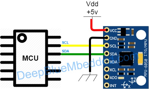
This sensor can be easily interfaced using a two-wire interface (i2c) as we’ll see in this tutorial. Without the need to use external pull-up resistors as they connected already on the sensor’s board.
Pinout & Connection Diagram
Features
Gyroscope Features:
- Digital-output X-, Y-, and Z-Axis angular rate sensors (gyroscopes) with a user-programmable full-scale range of ±250, ±500, ±1000, and ±2000°/sec
- Integrated 16-bit ADCs enable simultaneous sampling of gyros
- Enhanced bias and sensitivity temperature stability reduces the need for user calibration
- Improved low-frequency noise performance
- Digitally-programmable low-pass filter
- Factory calibrated sensitivity scale factor
Accelerometer Features:
- Digital-output triple-axis accelerometer with a programmable full-scale range of ±2g, ±4g, ±8g, and ±16g
- Integrated 16-bit ADCs enable simultaneous sampling of accelerometers while requiring no external multiplexer
- Orientation detection and signaling
- Tap detection
- User-programmable interrupts
Extra Features:
- 9-Axis MotionFusion by the on-chip Digital Motion Processor (DMP)
- VDD supply voltage range of 2.375V-3.46V
- 1024 byte FIFO buffer reduces power consumption by allowing the host processor to read the data in bursts and then go into a low-power mode as the MPU collects more data
- Digital-output temperature sensor
- User-programmable digital filters for gyroscope, accelerometer, and temp sensor
- 400kHz Fast Mode I2C for communicating with all registers
Applications
- Robotic Motion Sensing And Control
- Robotics Localization And Mapping Tasks
- MotionCommand™ technology (for Gesture Short-cuts)
- Motion-enabled game and application framework
- InstantGesture™ iG™ gesture recognition
- Location-based services, points of interest, and dead reckoning
- Handset and portable gaming
- Motion-based game controllers
- 3D remote controls for Internet-connected TVs and set-top boxes, 3D mice, etc
- Wearable sensors for health, fitness, and sports
- Toys
- And Much More…
Block Diagram
3-Axis Gyroscope
The MPU-60X0 consists of three independent vibratory MEMS rate gyroscopes, which detect rotation about the X-, Y-, and Z- Axes. When the gyros are rotated about any of the sense axes, the Coriolis Effect causes a vibration that is detected by a capacitive pickoff. The resulting signal is amplified, demodulated, and filtered to produce a voltage that is proportional to the angular rate. This voltage is digitized using individual on-chip 16-bit Analog-to-Digital Converters (ADCs) to sample each axis.
The full-scale range of the gyro sensors may be digitally programmed to ±250, ±500, ±1000, or ±2000 degrees per second (dps). The ADC sample rate is programmable from 8,000 samples per second, down to 3.9 samples per second, and user-selectable low-pass filters enable a wide range of cut-off frequencies.
3-Axis Accelerometer
The MPU-60X0’s 3-Axis accelerometer uses separate proof masses for each axis. Acceleration along a particular axis induces displacement on the corresponding proof mass, and capacitive sensors detect the displacement differentially. The MPU-60X0’s architecture reduces the accelerometers’ susceptibility to fabrication variations as well as to thermal drift.
When the device is placed on a flat (horizontal) surface, it will measure 0g on the X- and Y-axes and +1g on the Z-axis. The accelerometers’ scale factor is calibrated at the factory and is nominally independent of the supply voltage. Each sensor has a dedicated sigma-delta ADC for providing digital outputs. The full-scale range of the digital output can be adjusted to ±2g, ±4g, ±8g, or ±16g. Note that: +1g is equal to = 9.8m/s2 Which is the gravitational acceleration.
Digital Motion Processor (DMP)
The DMP acquires data from accelerometers, gyroscopes, and additional 3rd party sensors such as magnetometers, and processes the data. The resulting data can be read from the DMP’s registers or can be buffered in a FIFO. The DMP has access to one of the MPU’s external pins, which can be used for generating interrupts.
The purpose of the DMP is to offload both timing requirements and processing power from the host processor. Typically, motion processing algorithms should be run at a high rate, often around 200Hz, in order to provide accurate results with low latency. This is required even if the application updates at a much lower rate.
Sensor Data Registers
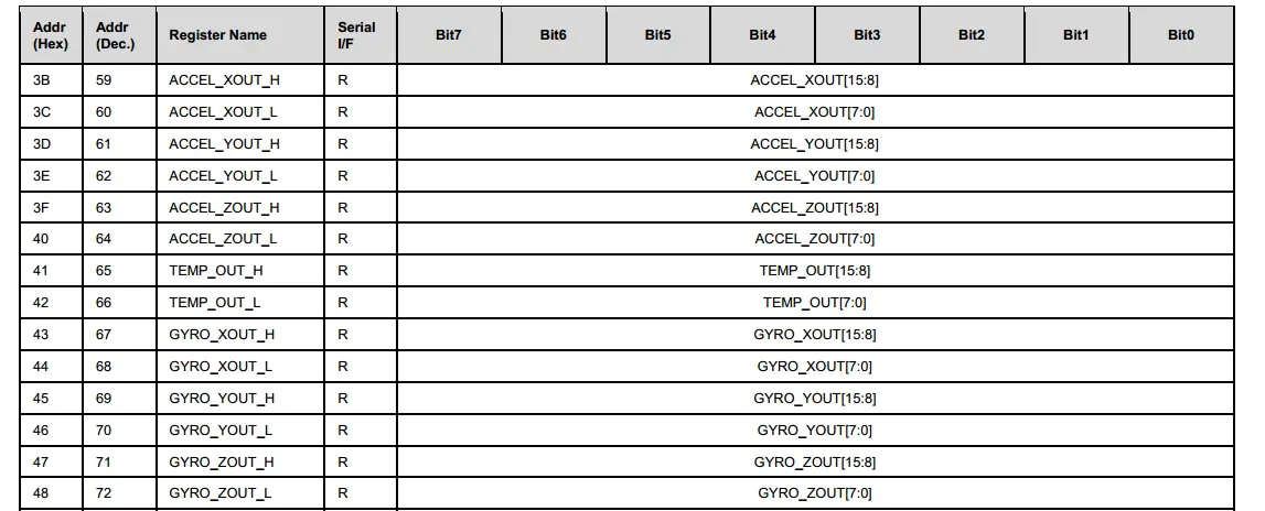
The sensor data registers contain the latest gyro, accelerometer, auxiliary sensor, and temperature measurement data. They are read-only registers and are accessed via the serial interface. Data from these registers may be read anytime. However, the interrupt function may be used to determine when new data is available.
FIFO Memory
The MPU6050 contains a 1024-byte FIFO register that is accessible via the Serial Interface. The FIFO configuration register determines which data is written into the FIFO. Possible choices include gyro data, accelerometer data, temperature readings, auxiliary sensor readings, and FSYNC input. A FIFO counter keeps track of how many bytes of valid data are contained in the FIFO. The FIFO register supports burst reads. The interrupt function may be used to determine when new data is available.
Interrupts
Interrupt functionality is configured via the Interrupt Configuration register. The interrupt status can be read from the Interrupt Status register.
The MPU6050 has a programmable interrupt system which can generate an interrupt signal on the INT pin. Status flags indicate the source of an interrupt. Interrupt sources may be enabled and disabled individually.

Register Map
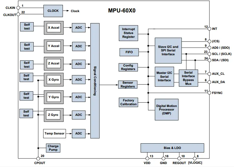
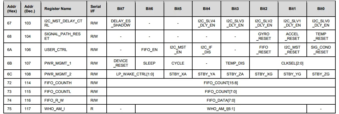
As you’ve seen in the above block diagram that the memory registers are easily accessible by different modules on the data bus. The Acceleration, Gyro, and Temperature sensing results are written to specific registers in the memory (which are read-only for the I2C host module). Some other registers are used by the DMP to set its configurations and others for setting the sampling rate, ranges, and other parameters for the Acc & Gyro.
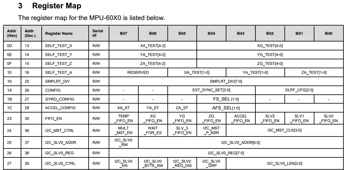
We need to know the addresses and functionality of these registers in order to send the desired configurations to the right registers & read the results from the right memory locations! Down below are snippets from the memory map from the sensor’s datasheet. We’ll copy it to a header file in our code later on.
To Get The Full Register Map For MPU6050
Registers’ Descriptions
As I’ve mentioned earlier, each register has specific functionality and it may be read/write or Read-Only. All these pieces of information are detailed in the MPU6050 register map document. And I highly recommend you download it and have a look at some of these registers.
Here is an example for a register that is used to configure the Accelerometer, for example, it’s called ACCEL_CONFIG (which makes a lot of sense in fact!)

ACCEL_CONFIG Register Description
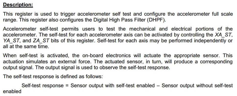
This register is used to trigger the accelerometer self-test and configure the accelerometer full-scale range. This register also configures the Digital High Pass Filter (DHPF). The accelerometer self-test permits users to test the mechanical and electrical portions of the accelerometer. The self-test for each accelerometer axis can be activated by controlling the XA_ST, YA_ST, and ZA_ST bits of this register. Self-test for each axis may be performed independently or all at the same time.
When the self-test is activated, the on-board electronics will actuate the appropriate sensor. This actuation simulates an external force. The actuated sensor, in turn, will produce a corresponding output signal. The output signal is used to observe the self-test response.
AFS_SEL selects the full-scale range of the accelerometer outputs according to the following table.
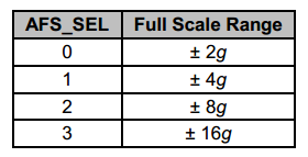
And that’s it for this single register. There are many others out there in the specifications document. Just take the time to skip through it and highlight each register/bit you see interesting to get a specific functionality out of your MPU6050 sensor to make the best use of it!
Interfacing MPU6050 With PIC MCUs
Connection Diagram (Hardware)

Driver Components (Software Parts)
Serial Terminal: For debugging purposes, we’ll need to send out the sensor’s data over the UART serial port to the computer so we can check its validity.
I2C Driver: the MPU6050 interface we’ll be using is built on the I2C communication protocol and we’ll need the I2C hardware device driver code which we’ve developed in a previous tutorial. You’ll have to change this code if you’re planning to use another PIC MCU chip or even AVR MCU.
Register Map Definitions: For MPU6050 interfacing, we’ll need to address each register individually and by its own address stated in the specifications sheet. So, we’ll create a header file with all registers names and addresses to be used in the MPU6050.c source code file.
Initialization Settings For MPU6050: The MPU6050.c source file must have at least a single function (routine) to initialize the required settings for the sensor during operation. You can add more functions to change the data rate or the range of readings for each of the accelerometer and the gyroscope. Actually you can add more functionality to control how the MPU6050 will operate. But all in all, you’ll need at least a single initialization function MPU6050_Init();
Raw Data Reading: The MPU6050.c source file should also include a function to get the readings from the sensor. You can either create separate functions to read each sensor at a time (accelerometer, gyro, or temperature). But as you can see, at least, one function can be used at least to get all the raw sensor’s readings/data. Mathematical manipulations and conversions can thereafter be applied to this data. More functions can be added to our library’s source file MPU6050.c, but I’ll implement Raw_Data_Read() for this tutorial. Then you can replicate what other guys are doing with Arduino and so.
Implementing MPU6050 Driver (Raw)
1 Serial Port
The readings from the sensor will be printed over the UART-USB converter, so we’ll need the following routines. Which we’ve developed in a previous tutorial (UART).
|
1 2 3 |
void UART_TX_Init(void); void UART_Write(unsigned char); void UART_Write_String(char*); |
2 I2C Driver
In order to communicate with the MPU6050 sensor, we’ll need to use our I2C device driver which we’ve implemented in a previous tutorial (I2C). Here are the prototypes for these functions. The exact implementation (functions’ definitions) can be found in the next LAB hereafter or in the I2C tutorial itself.
|
1 2 3 4 5 6 7 8 9 10 11 |
void I2C_Master_Init(); void I2C_Master_Wait(); void I2C_Master_Start(); void I2C_Start(char add); void I2C_Master_RepeatedStart(); void I2C_Master_Stop(); void I2C_ACK(); void I2C_NACK(); unsigned char I2C_Master_Write(unsigned char data); unsigned char I2C_Read_Byte(); unsigned char I2C_Read(unsigned char); |
3 MPU6050 Register Map Definitions
|
1 2 3 4 5 6 7 8 9 10 11 12 13 14 15 16 17 18 19 20 21 22 23 24 25 26 27 28 29 30 31 32 33 34 35 36 37 38 39 40 41 42 43 44 45 46 47 48 49 50 51 52 53 54 55 56 57 58 59 60 61 62 63 64 65 66 67 68 69 70 71 72 73 74 75 76 77 78 79 80 81 82 83 84 85 86 87 88 89 90 91 92 93 94 95 96 97 98 99 100 101 102 103 104 105 106 107 108 109 110 111 |
//----------[ MPU6050 Register Map ]----------- #define XG_OFFS_TC 0x00 #define YG_OFFS_TC 0x01 #define ZG_OFFS_TC 0x02 #define X_FINE_GAIN 0x03 #define Y_FINE_GAIN 0x04 #define Z_FINE_GAIN 0x05 #define XA_OFFS_H 0x06 #define XA_OFFS_L_TC 0x07 #define YA_OFFS_H 0x08 #define YA_OFFS_L_TC 0x09 #define ZA_OFFS_H 0x0A #define ZA_OFFS_L_TC 0x0B #define XG_OFFS_USRH 0x13 #define XG_OFFS_USRL 0x14 #define YG_OFFS_USRH 0x15 #define YG_OFFS_USRL 0x16 #define ZG_OFFS_USRH 0x17 #define ZG_OFFS_USRL 0x18 #define SMPLRT_DIV 0x19 #define CONFIG 0x1A #define GYRO_CONFIG 0x1B #define ACCEL_CONFIG 0x1C #define FF_THR 0x1D #define FF_DUR 0x1E #define MOT_THR 0x1F #define MOT_DUR 0x20 #define ZRMOT_THR 0x21 #define ZRMOT_DUR 0x22 #define FIFO_EN 0x23 #define I2C_MST_CTRL 0x24 #define I2C_SLV0_ADDR 0x25 #define I2C_SLV0_REG 0x26 #define I2C_SLV0_CTRL 0x27 #define I2C_SLV1_ADDR 0x28 #define I2C_SLV1_REG 0x29 #define I2C_SLV1_CTRL 0x2A #define I2C_SLV2_ADDR 0x2B #define I2C_SLV2_REG 0x2C #define I2C_SLV2_CTRL 0x2D #define I2C_SLV3_ADDR 0x2E #define I2C_SLV3_REG 0x2F #define I2C_SLV3_CTRL 0x30 #define I2C_SLV4_ADDR 0x31 #define I2C_SLV4_REG 0x32 #define I2C_SLV4_DO 0x33 #define I2C_SLV4_CTRL 0x34 #define I2C_SLV4_DI 0x35 #define I2C_MST_STATUS 0x36 #define INT_PIN_CFG 0x37 #define INT_ENABLE 0x38 #define DMP_INT_STATUS 0x39 #define INT_STATUS 0x3A #define ACCEL_XOUT_H 0x3B #define ACCEL_XOUT_L 0x3C #define ACCEL_YOUT_H 0x3D #define ACCEL_YOUT_L 0x3E #define ACCEL_ZOUT_H 0x3F #define ACCEL_ZOUT_L 0x40 #define TEMP_OUT_H 0x41 #define TEMP_OUT_L 0x42 #define GYRO_XOUT_H 0x43 #define GYRO_XOUT_L 0x44 #define GYRO_YOUT_H 0x45 #define GYRO_YOUT_L 0x46 #define GYRO_ZOUT_H 0x47 #define GYRO_ZOUT_L 0x48 #define EXT_SENS_DATA_00 0x49 #define EXT_SENS_DATA_01 0x4A #define EXT_SENS_DATA_02 0x4B #define EXT_SENS_DATA_03 0x4C #define EXT_SENS_DATA_04 0x4D #define EXT_SENS_DATA_05 0x4E #define EXT_SENS_DATA_06 0x4F #define EXT_SENS_DATA_07 0x50 #define EXT_SENS_DATA_08 0x51 #define EXT_SENS_DATA_09 0x52 #define EXT_SENS_DATA_10 0x53 #define EXT_SENS_DATA_11 0x54 #define EXT_SENS_DATA_12 0x55 #define EXT_SENS_DATA_13 0x56 #define EXT_SENS_DATA_14 0x57 #define EXT_SENS_DATA_15 0x58 #define EXT_SENS_DATA_16 0x59 #define EXT_SENS_DATA_17 0x5A #define EXT_SENS_DATA_18 0x5B #define EXT_SENS_DATA_19 0x5C #define EXT_SENS_DATA_20 0x5D #define EXT_SENS_DATA_21 0x5E #define EXT_SENS_DATA_22 0x5F #define EXT_SENS_DATA_23 0x60 #define MOT_DETECT_STATUS 0x61 #define I2C_SLV0_DO 0x63 #define I2C_SLV1_DO 0x64 #define I2C_SLV2_DO 0x65 #define I2C_SLV3_DO 0x66 #define I2C_MST_DELAY_CTRL 0x67 #define SIGNAL_PATH_RESET 0x68 #define MOT_DETECT_CTRL 0x69 #define USER_CTRL 0x6A #define PWR_MGMT_1 0x6B #define PWR_MGMT_2 0x6C #define BANK_SEL 0x6D #define MEM_START_ADDR 0x6E #define MEM_R_W 0x6F #define DMP_CFG_1 0x70 #define DMP_CFG_2 0x71 #define FIFO_COUNTH 0x72 #define FIFO_COUNTL 0x73 #define FIFO_R_W 0x74 #define WHO_AM_I 0x75 |
4 MPU6050 Initialization Settings
You can actually create multiple functions (routines) to set the configurations of the MPU6050 sensor or alternatively, for sake of simplicity, we can put all together in a single function which will be called afterward to initialize the MPU6050 with some default settings of our choice! let’s call it
|
1 |
void MPU6050_Init(); |
The implementation (definition) of this function will be as shown below
|
1 2 3 4 5 6 7 8 9 10 11 12 13 14 15 16 17 18 19 20 21 22 23 24 25 26 27 28 29 30 31 32 33 34 35 36 37 38 39 40 41 42 |
void MPU6050_Init() { // Power-Up Delay & I2C_Init __delay_ms(100); I2C_Master_Init(); // Setting The Sample (Data) Rate I2C_Start(0xD0); I2C_Master_Write(SMPLRT_DIV); I2C_Master_Write(0x07); I2C_Master_Stop(); // Setting The Clock Source I2C_Start(0xD0); I2C_Master_Write(PWR_MGMT_1); I2C_Master_Write(0x01); I2C_Master_Stop(); // Configure The DLPF I2C_Start(0xD0); I2C_Master_Write(CONFIG); I2C_Master_Write(0x00); I2C_Master_Stop(); // Configure The ACCEL (FSR= +-2g) I2C_Start(0xD0); I2C_Master_Write(ACCEL_CONFIG); I2C_Master_Write(0x00); I2C_Master_Stop(); // Configure The GYRO (FSR= +-2000d/s) I2C_Start(0xD0); I2C_Master_Write(GYRO_CONFIG); I2C_Master_Write(0x18); I2C_Master_Stop(); // Enable Data Ready Interrupts I2C_Start(0xD0); I2C_Master_Write(INT_ENABLE); I2C_Master_Write(0x01); I2C_Master_Stop(); } |
Down below are the different parts of this function’s implementation (definition)
4.1 Power-Up Delay & I2C Initialization
|
1 2 |
__delay_ms(100); I2C_Master_Init(); |
4.2 Setting The Sampling (data) Rate Divider

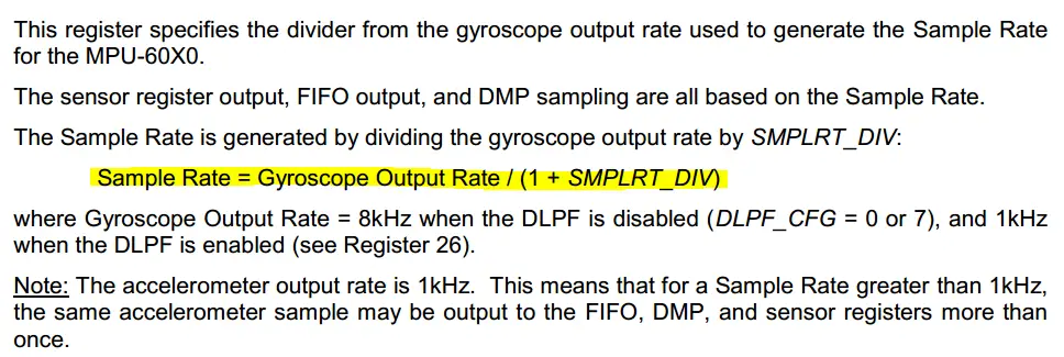
which means, if you want to set the sampling rate to 1kHz, all you have to do is passing 0x07 to this register in the MPU6050 memory. And that’s what we’re doing below
|
1 2 3 4 |
I2C_Start(0xD0); I2C_Master_Write(SMPLRT_DIV); I2C_Master_Write(0x07); I2C_Master_Stop(); |
4.3 Setting The MPU6050 Clock Source

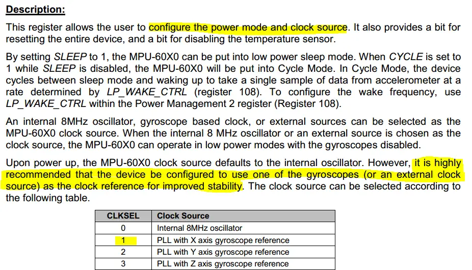
Which means, we can simply pass 0x01 to this register in the MPU6050’s memory. So that it uses the clock of the gyro and not put it in sleep mode as well. Here is how to pass this 0x01 value to the PWR_MGMT_1 register.
|
1 2 3 4 |
I2C_Start(0xD0); I2C_Master_Write(PWR_MGMT_1); I2C_Master_Write(0x01); I2C_Master_Stop(); |
4.4 Configure The Digital Low Pass Filter (DLPF)

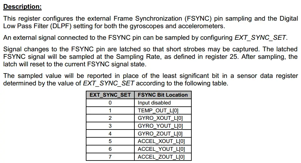
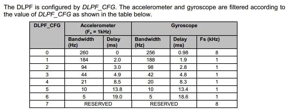
We’ll not use external input so we don’t need the sync function and for the digital low pass filter inside the MPU6050, we’ll pick the highest bandwidth frequency, just to test out how stable the readings will be. Therefore, the value which we’ll write to the CONFIG register will be 0x00. And here is how to pass it to the MPU6050 register in C.
|
1 2 3 4 |
I2C_Start(0xD0); I2C_Master_Write(CONFIG); I2C_Master_Write(0x00); I2C_Master_Stop(); |
4.5 Configure The Accelerometer

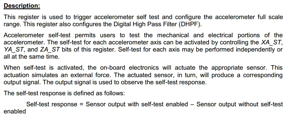
 We won’t use the self-test feature in these tutorials, so we don’t need to configure anything about it. And as for the full-scale range, we’ll pick ± 2g (which is= ± 2 x 9.8 m/s2). You can create a separate function just to set the FSR of the accelerometer so the user has the ability to easily pick the value he wants. But for this tutorial, we’ll keep it fixed to ±2g. So, we’ll move 0x00 to ACCEL_CONFIG register. And here is how to do this in C, so you can easily change it however you want in your application.
|
1 2 3 4 |
I2C_Start(0xD0); I2C_Master_Write(ACCEL_CONFIG); I2C_Master_Write(0x00); I2C_Master_Stop(); |
4.6 Configure The Gyroscope


As we’ve done with the accelerometer previously, the self-test mode won’t be used in this tutorial. And as for the full-scale range, let’s pick the widest range span ±2000 °/s. Therefore, the value which we’ll have to pass to the GYRO_CONFIG register will be 0x18. You can change the range however you want. And here is how to do it in code.
|
1 2 3 4 |
I2C_Start(0xD0); I2C_Master_Write(GYRO_CONFIG); I2C_Master_Write(0x18); I2C_Master_Stop(); |
4.7 Enable Internal Interrupts (When Data Ready)

To enable the internal interrupts when data is ready, we’ll need to move 0x01 to the INT_ENABLE register inside the MPU6050’s memory. And here is the code to do this.
|
1 2 3 4 |
I2C_Start(0xD0); I2C_Master_Write(INT_ENABLE); I2C_Master_Write(0x01); I2C_Master_Stop(); |
Finally: you can read the WHO_AM_I register and check if the sensor is responding correctly or not. If not, then return 0, if yes, return 1. And yes, you’ll need to change the function’s type it won’t be void anymore.
|
1 |
unsigned char MPU6050_Init(); |
In this way, you can check the returned value in your main function. This enables the user to determine if the MPU6050 sensor is working and initialized successfully or not! And that’s it! we won’t do this in our tutorial to keeps things as simple as possible, but here you got it. DIY it if you want!
5 Raw Data Reading
The reading from MPU6050 IMU consists of 7 parameters saved in 14 consecutive registers in the memory. We’ll need to read them all one by one. (1) Accelerometer readings ACCEL_X, ACCEL_Y, ACCEL_Z. (2) Gyroscope readings GYRO_X, GYRO_Y, GYRO_Z. (3) Temperature sensor value.
Firstly, we’ll send the address of the first register containing the results (readings) and it’s ACCEL_XOUT_H. After reading this register from the MPU6050, the MCU should ACK receiving it, so the MPU6050 will send out the next register’s value and so on until we’ve received the 14 registers successfully. Then, the MCU will NACK and stop the I2C communication.
We can return the results as an array of integers or even pass a buffer array by reference to the Read() function which will write the readings into it directly using the pointer. However, and for the sake of simplicity, in this tutorial we’ll just print out the results to the terminal within the Read() function itself. So, it’s going to be void.
And here you got the idea, implement the return method on your own until another tutorial is released in the future. Or maybe I’ll just add it as an update at the conclusion of this article, IDK.
Here is the implementation of the Read() function!
|
1 2 3 4 5 6 7 8 9 10 11 12 13 14 15 16 17 18 19 20 21 22 23 24 25 26 27 28 29 30 31 32 33 34 35 36 37 38 39 |
void MPU6050_Read() { char buffer[40]; int Ax, Ay, Az, Gx, Gy, Gz, T; // Prepare For Reading, Starting From ACCEL_XOUT_H I2C_Start(0xD0); I2C_Master_Write(ACCEL_XOUT_H); I2C_Master_Stop(); I2C_Start(0xD1); Ax = ((int)I2C_Read(0)<<8) | (int)I2C_Read(0); Ay = ((int)I2C_Read(0)<<8) | (int)I2C_Read(0); Az = ((int)I2C_Read(0)<<8) | (int)I2C_Read(0); T = ((int)I2C_Read(0)<<8) | (int)I2C_Read(0); Gx = ((int)I2C_Read(0)<<8) | (int)I2C_Read(0); Gy = ((int)I2C_Read(0)<<8) | (int)I2C_Read(0); Gz = ((int)I2C_Read(0)<<8) | (int)I2C_Read(1); I2C_Master_Stop(); sprintf(buffer,"Ax = %d ",Ax); UART_Write_String(buffer); sprintf(buffer," Ay = %d ",Ay); UART_Write_String(buffer); sprintf(buffer," Az = %d ",Az); UART_Write_String(buffer); sprintf(buffer," T = %d ",T); UART_Write_String(buffer); sprintf(buffer," Gx = %d ",Gx); UART_Write_String(buffer); sprintf(buffer," Gy = %d ",Gy); UART_Write_String(buffer); sprintf(buffer," Gz = %d\r\n",Gz); UART_Write_String(buffer); } |
MPU6050 Raw Example – LAB1
MPU6050 Interfacing With PIC16F877A
| Lab Name | Interfacing MPU6050 Raw Data Read Example |
| Lab Number | 35 |
| Lab Level | Intermediate |
| Lab Objectives | Learn how to interface the MPU6050 Accelerometer/Gyroscope IMU with a microcontroller over the I2C serial bus. |
1. Coding
Open the MPLAB IDE and create a new project, name it “MPU6050_Raw”. If you have some issues doing so, you can always refer to the previous tutorial using the link below.
Set the configuration bits to match the generic setting which we’ve stated earlier. And if you also find troubles creating this file, you can always refer to the previous tutorial using the link below.
Now, open the main.c file and let’s start developing the firmware for our project.
Here is the Full Code Listing For This LAB
|
1 2 3 4 5 6 7 8 9 10 11 12 13 14 15 16 17 18 19 20 21 22 23 24 25 26 |
/* * File: main.c * Author: Khaled Magdy * LAB: MPU6050 Raw Data Example (PIC16F877A) * LAB#: 35 */ #include <xc.h> #include <stdio.h> #include "config.h" #include "UART.h" #include "MPU6050.h" void main(void) { UART_TX_Init(); TRISC2 = 0; // LED Indicator MPU6050_Init(); while(1) { RC2 = ~RC2; // Blink LED MPU6050_Read(); __delay_ms(50); } return; } |
2. Prototyping
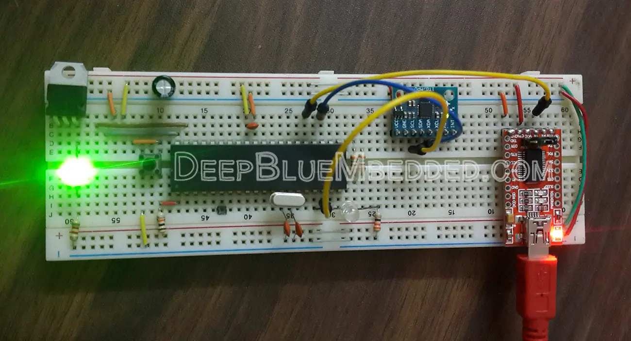
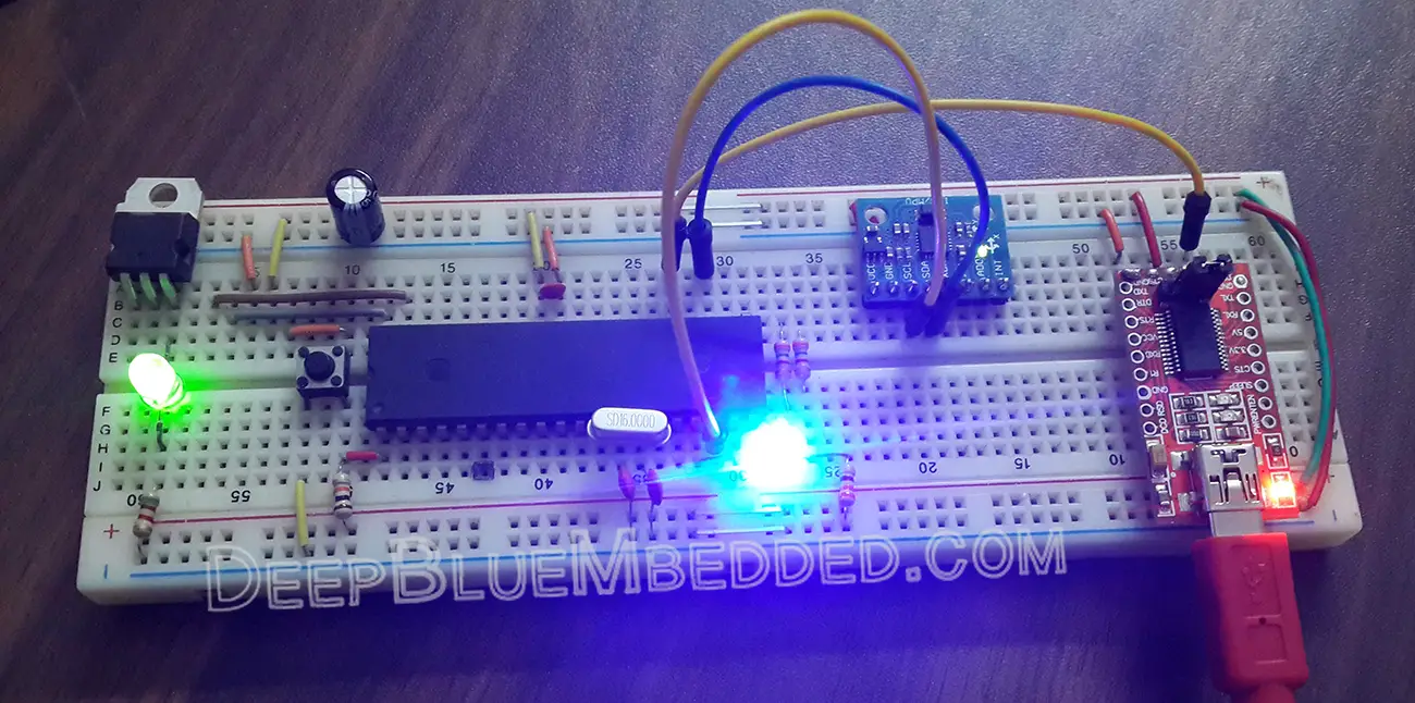
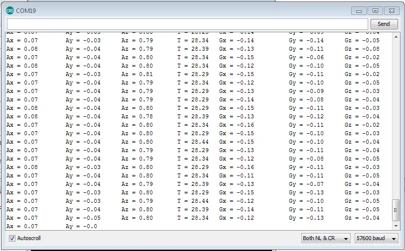
And here are the results (Raw Sensors Data) on the terminal screen. It may not make a lot of sense to you if it’s your first time dealing with this IMU. But for me, this makes a lot of sense XD!
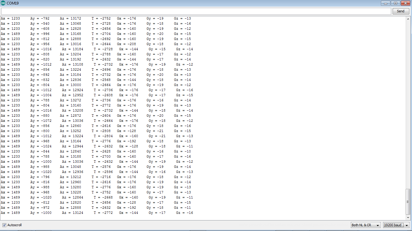
Put the sensor in a horizontal position and notice only the value of Az, it should be as near as possible to 214=16384. As you can see in the data, it’s close enough. Try pointing the module in such a way that the x-direction mark on the board is facing the ground. Now, Ax value should be approaching 16384. And the same for y-direction.
The catch is: the full-scale range we’re using is 2g and the acceleration result is signed int 16 -bit. So it’s ranging from (-32768 to +32768) which corresponds to (-2g to +2g). The gravitational acceleration is +1g which means the sensor’s reading will be nearly 16384 and in the same direction towards the earth.
MPU6050 Converted Data – LAB2
MPU6050 Interfacing With PIC18F2550
| Lab Name | Interfacing MPU6050 Converted Data Example |
| Lab Number | 36 |
| Lab Level | Intermediate |
| Lab Objectives | Learn how to interface the MPU6050 Accelerometer/Gyroscope IMU with a microcontroller over the I2C serial bus. |
1. Coding
Open the MPLAB IDE and create a new project, name it “MPU6050”. If you have some issues doing so, you can always refer to the previous tutorial using the link below.
Set the configuration bits to match the generic setting which we’ve stated earlier. And if you also find troubles creating this file, you can always refer to the previous tutorial using the link below.
Now, open the main.c file and let’s start developing the firmware for our project.
Here is the Full Code Listing For This LAB
|
1 2 3 4 5 6 7 8 9 10 11 12 13 14 15 16 17 18 19 20 21 22 23 |
/* * File: main.c * Author: Khaled Magdy * LAB: MPU6050 Converted Data Example (PIC18F2550) * LAB#: 36 */ #include <xc.h> #include "config.h" #include "UART.h" #include "MPU6050.h" void main(void) { UART_TX_Init(); MPU6050_Init(); while(1) { MPU6050_Read(); __delay_ms(50); } return; } |
Here is the implementation for the MPU6050_Read() function
|
1 2 3 4 5 6 7 8 9 10 11 12 13 14 15 16 17 18 19 20 21 22 23 24 25 26 27 28 29 30 31 32 33 34 35 36 37 38 39 40 41 42 43 44 45 46 47 48 49 50 51 52 |
void MPU6050_Read() { char buffer[40]; int Ax,Ay,Az,T,Gx,Gy,Gz; float AX, AY, AZ, t, GX, GY, GZ; // Prepare For Reading, Starting From ACCEL_XOUT_H I2C_Start(0xD0); I2C_Master_Write(ACCEL_XOUT_H); I2C_Master_Stop(); I2C_Start(0xD1); I2C_Read(0); // dummy Ax = ((int)I2C_Read(0)<<8) | (int)I2C_Read(0); Ay = ((int)I2C_Read(0)<<8) | (int)I2C_Read(0); Az = ((int)I2C_Read(0)<<8) | (int)I2C_Read(0); T = ((int)I2C_Read(0)<<8) | (int)I2C_Read(0); Gx = ((int)I2C_Read(0)<<8) | (int)I2C_Read(0); Gy = ((int)I2C_Read(0)<<8) | (int)I2C_Read(0); Gz = ((int)I2C_Read(0)<<8) | (int)I2C_Read(1); I2C_Master_Stop(); // Convert The Readings AX = (float)Ax/16384.0; AY = (float)Ay/16384.0; AZ = (float)Az/16384.0; GX = (float)Gx/131.0; GY = (float)Gy/131.0; GZ = (float)Gz/131.0; t = ((float)T/340.00)+36.53; // Print The Results sprintf(buffer,"Ax = %.2f \t",AX); UART_Write_String(buffer); sprintf(buffer," Ay = %.2f \t",AY); UART_Write_String(buffer); sprintf(buffer," Az = %.2f \t",AZ); UART_Write_String(buffer); sprintf(buffer," T = %.2f ",t); UART_Write_String(buffer); sprintf(buffer," Gx = %.2f \t",GX); UART_Write_String(buffer); sprintf(buffer," Gy = %.2f \t",GY); UART_Write_String(buffer); sprintf(buffer," Gz = %.2f\r\n",GZ); UART_Write_String(buffer); } |
2. Prototyping
Here are the results on the serial terminal (Converted Sensors Data).
Stick Speed Controller – LAB3
The MCU I’ve Used For This LAB is PIC18F2550
| Lab Name | Stick Speed Controller With MPU6050 |
| Lab Number | 37 |
| Lab Level | Intermediate |
| Lab Objectives | Learn how to interface the MPU6050 Accelerometer/Gyroscope IMU with a microcontroller over the I2C serial bus. |
1. Coding
Open the MPLAB IDE and create a new project, name it “MPU6050_Stick”. If you have some issues doing so, you can always refer to the previous tutorial using the link below.
Set the configuration bits to match the generic setting which we’ve stated earlier. And if you also find troubles creating this file, you can always refer to the previous tutorial using the link below.
Now, open the main.c file and let’s start developing the firmware for our project.
Here is the Full Code Listing For This LAB
|
1 2 3 4 5 6 7 8 9 10 11 12 13 14 15 16 17 18 19 20 21 22 23 24 25 |
/* * File: main.c * Author: Khaled Magdy * LAB: MPU6050 Speed Control Stick * LAB#: 37 */ #include <xc.h> #include <stdint.h> #include "PWM.h" #include "config.h" #include "MPU6050.h" #define _XTAL_FREQ 48000000 void main(void) { Setup_PWM1(); MPU6050_Init(); while(1) { MPU6050_Read(); __delay_ms(50); } return; } |
As you might have noticed, nothing interesting happens in the main.c file actually!
The PWM duty cycle is being changed in the MPU6050_Read() function. And this is done according to the reading of acceleration in the y-Axis direction. The stick I’ve built has a pivot point in such a way it rotates around the y-axis. So the acceleration affecting on the y-axis is the gravitational acceleration = +1g = 9.81m/s2 or in the digital world (as for the sensor output) it’s ±16384
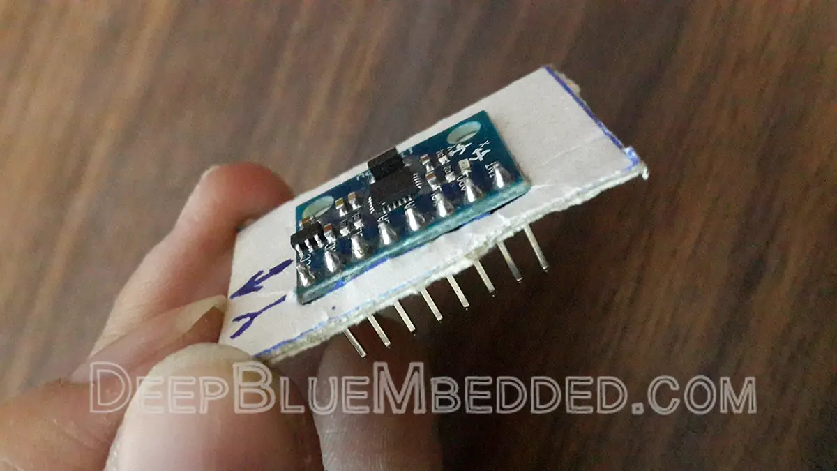
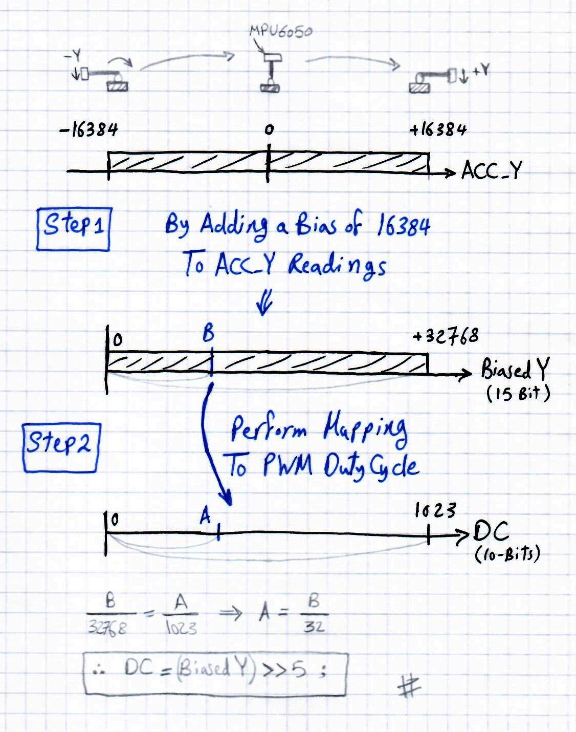
When the MPU6050 accelerometer sensor is pointing in -y direction, the reading of the sensor will be -16384 and moving the stick to the other end will make the sensor pointing in +y direction and the sensor data output will be +16384, and in between the data from the sensor will be between those two end limits.
Step1 is to add a bias to this result from the sensor in order to get a positive value as a result ranging from 0 up to 32768.
Step2 is to perform a mapping from this domain to the PWM duty cycle which will be set to 10-Bits of resolution. Ranging from 0 up to 1023 (0-100% DC). This can be done by dividing by 32 or left-shifting the result >>5 times!
This figure explains what I’m trying to say in a graphical way
Note: in order to get 10-Bits of DutyCycle resolution, we’ll set the PWM frequency to 2.9kHz, Fosc=48MHz, Timer2PS=16. Refer to the resolution equation in the datasheet (PWM page).
Note: to eliminate flickering in the output DC (due to mechanical friction or whatever), you can reduce the bandwidth frequency of the digital low pass filter (DLPF) in the MPU6050 settings and that’s what I’ve done in the initialization code.
Another Note: please, check the code of PWM settings to get an idea of what i’m talking about. Also, check the initialization function for MPU6050 to see how i’ve changed the settings of the DLPF, and check also the MPU6050_Read() function as it’s doing all the work i’ve explained earlier. And you can re-write it in a different way as it appeals to you. But first of all, take a look and see how things are working. The download link is available at the end of this LAB section.
2. Prototyping
Nothing interesting in connections for this lab. just hook the i2c lines to the sensor and give it power +5v. And take the PWM output to an LED or transistor driver for motor speed control. Here is a video demo for testing the final output of the system on an LED & DSO, then on a DC motor.
 |
Download the project code from the link down below. And check the functions I’ve highlighted previously in this article. And don’t hesitate to leave me any questions you’ve got. And also please, drop me a comment even if you’ve got everything right, I’m a little bit curious to know whether I could make everything clear or not.
Concluding Remarks
Will Be Added Soon!
You Can Support This Work By Sharing These Tutorials On Social Networks! I’d Really Appreciate That A lot!
| Previous Tutorial | Tutorial 29 | Next Tutorial | |||||


Hi Khaled and thank you for this tutorial! Is there a way to manually calibrate your accelerometer with PIC microcontroller, so that the start value is (0,0,0)?
Calibration is a whole different story. But what I can see from your question is what you’re searching for is biasing.
And yes, you can bias the result readings from the accelerometer to start from 0 and go up. This can easily be done by adding the minimum value for the current configuration (ex if you’re using +-2g sensitivity, then you can add 16384 to the result, and so on).
I am trying to do this project. Is there a circuit diagram for the hardware connections?
In lap3 you use PLL
How can i take the same code to make it work on pic16f877a
You don’t actually need the PLL in particular. However, in this lab you’ll need to store and manipulate floating point numbers and convert them to strings. I did use the standard sprintf function for that and the code side has grown up to the point where it can’t fit for pic16f877a. That’s why this lab in particular is done using a pic18f device. Aside of this, every thing is the same here and there.
Regards,
Hurrah! At last I got a blog from where I know how to in fact obtain valuable data regarding my study
and knowledge.
Awesome things here. I’m very satisfied to look your post.
Thank you so much and I’m looking forward to contact you.
Will you please drop me a e-mail?
thank you so much for this tutorial.
Good web site you have got here.. It’s difficult to find quality writing
like yours these days. I really appreciate people like you!
Take care!!
Hi sir! may i know if i wanted to use this coding for Atmega328p, what part do i need to change?
Only the I2C communication functions like the init, transmit/receive, i2c bus idle check, and so on.