| Previous Tutorial | Tutorial 18 | Next Tutorial | |||||
| UART Serial Communication Protocol | |||||||
| Intermediate Level ★★☆☆☆ | |||||||
In this tutorial, we’ll be discussing our first serial communication protocol (UART). You’ll get to know what is the UART serial communication protocol? How does it work? What are the typical applications for UART? We’ll also discuss in detail the process of creating the required firmware to drive the UART module in our PIC Microcontrollers. And finally, create a simple communication application MCU-To-MCU and test it out. It’s going to be a very long read with a massive amount of information, So let’s get started!
You may also need to check out the SPI (serial peripheral interface) tutorial. It’s another 10k words long-read kind of gigantic tutorial. Check it out and maybe keep it bookmarked as a guide for future work!
You may also need to check out the I2C Bus tutorial. It’s another 12k words long-read kind of gigantic tutorial. Check it out and maybe keep it bookmarked as a guide for future work!
[toc]
Required Components
| Qty. | Component Name | Buy On Amazon.com |
| 2 | PIC16F877A | Add |
| 2 | BreadBoard | Add |
| 8 | LED | Add Add |
| 1 | Resistors Kit | Add Add |
| 1 | Capacitors Kit | Add Add |
| 1 | Jumper Wires Pack | Add Add |
| 1 | USB-TTL Converter or FTDI Chip | Add Add |
| 1 | LM7805 Voltage Regulator (5v) | Add |
| 1 | Crystal Oscillator | Add |
| 1 | PICkit2 or 3 Programmer | Add |
| 2 | 9v Battery or DC Power Supply | Add Add Add |
Introduction To Serial Communication
In Embedded Systems, Telecommunication, and Data Transmission applications, Serial Communication is known to be the process of sending data one bit at a time (bit-by-bit) sequentially, over the serial bus. It takes a complete clock cycle in order to transfer each bit from an end to the other. Conversely, parallel communication is known to be the process of sending several bits, even bytes, as a whole only in a single clock cycle. However, even if you transfer fewer data per cycle with a serial transmission, you can do it at much higher frequencies which results in higher net transfer rates than of the parallel communication.
The Fundamental Concepts
There do exist many serial communication protocols, each of which is working in a different way. However, it turns out to be some similarity that they do share in common. Frankly speaking, serial communication protocols have Shift Registers somehow/somewhere in their hardware implementation as the working-horse (core). Shift registers are used to shift out the data to be transmitted bit-by-bit each clock cycle. So, let’s dig deeper into a shift register in order to build-up a complete understanding for what is actually happening at the Register(low)-Level.
Shift registers are basically some D-Flip-Flops serially connected while sharing the same clock line. Here is a graphical animation that demonstrates how does a shift register work internally.
As you might have noticed, the data input (0’s and 1’s) is being shifted from the input pin to the output end at bit-0. It takes only 1-clock to transfer a single bit, which means it takes 8-clocks for a single byte transfer. For the same of simplicity, we’ll represent the shift register as a single block instead of a series of D-Flip-Flops as shown above.
Here is an animation for an 8-Bit shift register with a serial input & serial output data lines.
Well, now you should know how shift registers are actually working. Frankly speaking, serial communication is as simple as connecting a couple of shift registers together! Connecting the data output of a shift register to be the data input of the other shift register enables us of sending digital data serially from an end to another!
In the following animation, I’m connecting a couple of 4-Bit shift registers. One at the transmitter device and the other at the receiver device. The serial bus consists of a couple of wires (data, and clock). Each clock, a bit is sent from the transmitter TX pin and received by the receiver’s RX pin.
As you might have noticed, it takes 4-clocks to send the 4-Bit data from the transmitter to the receiver. This is simply the short answer to the “How Serial Communication Works?”. However, it’s not everything you should know about serial communication or at least to the level of being able to implement a simple serial data transfer process.
In fact, there are some other options and configurations for each serial communication protocols. Which includes, various data transmission rates, error detection, and correction mechanisms, and much more that adds to the overall complexity associated with each protocol. We’ll be working with the UART protocol in this tutorial, which has a decent steep learning curve.
Serial VS Parallel Communication
As we’ve stated earlier, serial communication is the process of sending data each bit at a time (bit-by-bit). And conversely, the parallel communication is the process of sending multiple bits, even bytes, as a whole in a single clock cycle.
A very basic implementation, that you can create on your own, for the parallel data transfer is shown down below. As I’m connecting a couple of 4-Bit registers, via the 5-wire parallel bus (4-data pins + 1-clock). Here is an animation that shows you how parallel data transfer is done.
As you might have noticed, it takes only 1-clock to transfer the data from a transmitter device to the receiver! Frankly speaking, we can theoretically transfer any number of bits (or bytes) using parallel communication protocols in a single clock cycle at a time.
Here is a brief comparison between serial communication and parallel communication protocols.
| Feature | Serial Communication | Parallel Communication |
| Relative Speed | Faster | Slower |
| Distance Range | Much Farther | Shorter |
| Transfer Method | One bit is transmitted at a time | Bytes are transmitted in parallel, One byte or more at a time |
| Applications | Computer small peripherals, modules interfacing, and sensors measuring & sending simple data frames | Short distance High-Speed communication such as Computer printers, etc |
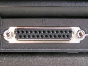
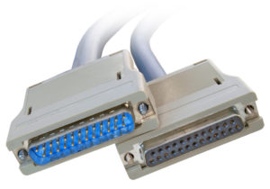
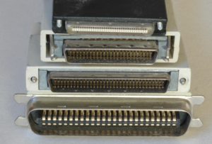
| Wires Inside | Few wires, all data bits pass only through the same data line | Multiple, more wires, each bit has a dedicated wire. So as to be transmitted all at once |
| Cables Pictures | 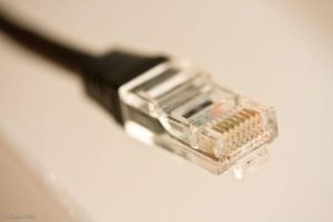 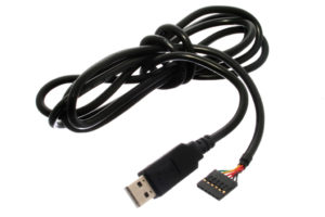 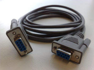 |
   |
Applications Of Serial Communication Protocols
There are countless situations in which we do use one or more of the serial communication protocols. Here, I’ll try to categorize the main purposes for which we use serial communication instead of listing down all possible applications that may be serving the same purposes. Hence, any application will, hopefully, possibly fall under the umbrella of the following purposes.
- External devices/modules communications
- Downloading / Updating The Firmware
- Console io
- Data Transmission
- Debugging interface
Serial communication protocols are of fundamental importance for each embedded systems application. And as embedded systems engineers, we must have a very solid experience with almost all of the commonly used serial communication protocols. And in the next sub-section, we’ll see a brief collection of the commonly available serial communication protocols in the embedded market.
Examples Of Serial Communication Protocols
There are many serial communication protocols that are existent and being used in various domains and sub-domains of embedded systems. Some of which are more likely to be used in the automotive industry such as LIN & CAN, some of which is more likely to be used for external memory interfacing as I2C, high-speed computer interfacing as USB, and for audio applications such as I2S. Here is a list of the most common serial communication protocols in the industry.
| USB | CAN | I2C |
| I2S | LIN | SPI |
| Ethernet | 1-Wire | UART/USART |
| And many more… | ||
We’ll be focusing only on the UART serial protocol in the rest of this tutorial. Just to understand the fundamentals & mechanics of UART communication. Only then, we’ll be able to develop the necessary firmware in order to transmit data from an embedded MCU to another as we’ll be doing the lab at the end of this tutorial. So, let’s get started with UART!
Introduction To UART
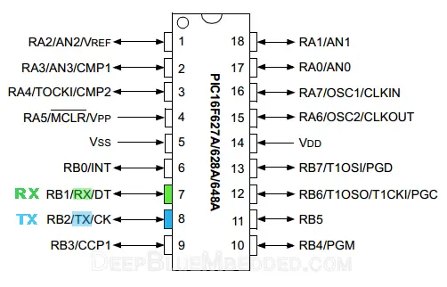
Universal Asynchronous Receiver/Transmitter or UART for short represents the hardware circuitry (module) being used for the serial communication. UART is sold/shipped as a standalone integrated circuit (IC) or as an internal module within microcontrollers. In this tutorial, we’re actually concerned with the internal UART module within PIC Microcontrollers.
There is a couple of io pins dedicated to the UART serial communication module highlighted in the following figure. Namely, RX (data input – receiving end) & TX (data output – transmitting end).
Forms Of UART Communication
There are actually two forms of UART as follows:
- UART – Universal Asynchronous Receiver/Transmitter
- USART – Universal Synchronous/Asynchronous Receiver/Transmitter
The Synchronous type of transmitters generates the data clock and sends it to the receiver which works accordingly in a synchronized manner. On the other hand, the Asynchronous type of transmitter generates the data clock internally. There is no incoming serial clock signal, so in order to achieve proper communication between the two ends, both of them must be using the same baud rate. The baud rate is the rate at which bits are being sent bps (bits per second).
| UART | USART |
| Standalone Communication Protocol | It can support multiple protocols like LIN, RS-485, IrDA, etc |
| Commonly used for low-speed applications | More suitable for high-speed applications |
| The data rate is relatively low | The data rate is much higher |
| The clock is generated locally and both devices are configured to run at the same baud rate | The clock signal is generated by the transmitter and sent to the receiver during data transmission |
| The baud rate of the receiver module must be known prior to any communication | The baud rate is useless as the receiver module will be using the clock coming from the transmitter device |
| Offer reduced low energy footprint even in sleep mode | Operates at high energy consumption modes |
So, is UART and USART are the same? Technically, NO! A USART generally has much more capabilities than a generic UART. Being able to generate clocked data allows the USART to operate at much higher baud rates way more than what a typical UART can handle.
Modes Of UART Communication
The communication over the UART bus can be configured (set) to be on one of the following modes:
- Simplex – One direction only, a transmitter to a receiver
- Half Duplex – Devices take turns transmitting and receiving
- Full Duplex – Devices can send and receive simultaneously (at the same time)
Modes Of Operation For UART Devices
The UART serial communication bus can only have 2 devices communicating with each other in one of the 3 modes shown in the previous sub-section. Which necessarily means, each device can either be a transmitter or a receiver during the data transmission process.
- Transmitter
- Receiver
You should know that the transmitter in synchronous mode must generate the serial data clock for the receiver. On the other hand, in asynchronous mode, there is no need to do so.
And there can’t be more than 2 devices on the UART serial bus. Otherwise, there will be some issues introduced to the system which you’ll have to work around.
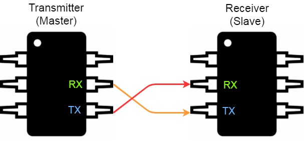
The proper connection for any 2 devices for UART serial communication goes as follows: the transmitter’s TX goes to the receiver’s RX and the receiver’s TX goes to the transmitter’s RX. Frankly speaking, the 2-wires are basically crossed!
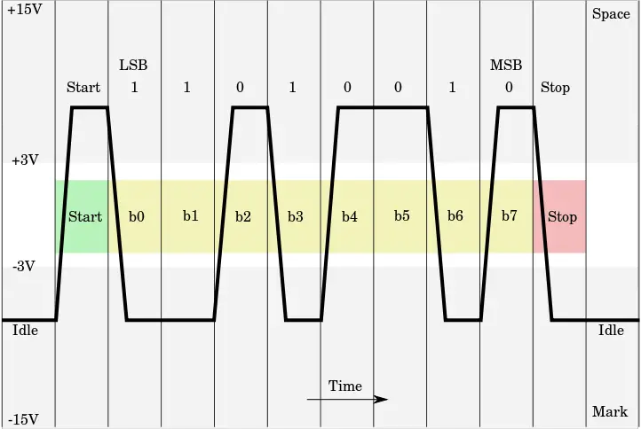
UART Data Packet
The data being transmitted/received in UART serial communication is organized into specific blocks called Packets. In the idle state, UART lines are pulled high. This allows the receiver side to recognize that there is a transmitter device on the other end which is connected to the serial bus. UART Packets usually start with “Start Bit” which is a logic low and is used to signal the receiver that there is a new coming packet. The structure of a typical UART Data Packet is shown in the figure down below.
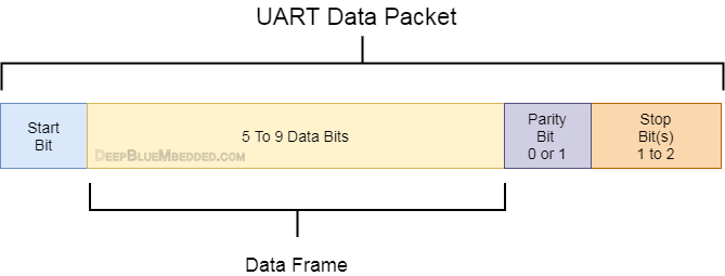
Start Bit
The UART data transmission line (TX) is normally held High (1) logic-level when there is no data transmission on the line. To start data transfer, the transmitting UART pulls-down the transmission line from high to low for one clock cycle. When the receiving UART module detects the high to low voltage transition, it begins reading the incoming bits of the entire data frame at the same frequency of the specified baud rate.
Data Frame
These are the actual data bits being transmitted from transmitter to receiver. The length of the data frame can be anywhere between 5 and 9 (9-Bits if parity is not used and 8-Bits if parity is used). In general settings, the LSB is the first bit to be shifted-out, transmitted, (unless otherwise specified).
Parity Bit
Parity bit allows the receiver to check the correctness of the received data. Parity is a low–level error checking mechanism and has two different options to choose from: Even Parity and Odd Parity. After the receiver UART reads the data frame, it counts the number of bits with a value of 1 and checks if the total value is an even or odd number. If the parity bit is a 0 (even parity), the number of bits with a value of 1 in the data frame should sum-up to an even number. If the parity bit is a 1 (odd parity), the number of bits with a value of 0 in the data frame should sum-up to an odd number. When the parity bit matches the data, the receiver UART knows that the transmission was a success. Frankly speaking, the parity bit is optional and it’s actually not widely used.
Stop Bit
As the name suggests, this bit is used to signal the end of the data packet being sent. The sending UART drives the data transmission line from low to high for at least two-bit durations but most often only one bit is used. The data line is held high back to the idle state and ready for any future transmission.
Baud Rate
The Baud Rate specifies how fast the data is sent over the bus and it is specified in bits-per-second or bps. You can actually choose any speed for the baud rate. However, there are some specific values that are known to be the industry standards. The most common and widely-used standardized value is 9600. Other standard baud rates include: 1200, 2400, 4800, 19200, 38400, 57600 and 115200. Obviously, baud rates are always multiples of 300. Baud rates higher than 115200(bps) can be used with an additional probability of having, at best, missing data packets. The rule of thumb in UART communication is, both the transmitter and the Receiver UART must agree on the exact same Baud Rate for a successful data transmission.
Digital Block Diagram (UART Transmitter)
Here is the block diagram for a generic UART transmitter module as found in PIC16F87XA devices’ datasheet (fig-10.1, page-115).
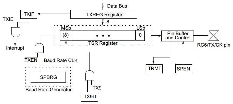
A Brief Description For UART Transmission Process
In UART transmitter mode, a byte of data is written to the 8-Bit TXREG register. Then it’s latched to the TSR transmitter shift register combined with the 9th bit (if used). The data is shifted out through the TX/RC6 physical pin at a rate specified by the BRG baud rate generator. The baud rate is pre-determined and pre-configured by us (the programmers) in order to match the design specifications. Setting the baud rate to be generated is as easy as writing a byte-value to the SPBRG register. The value is precisely calculated using a specific formula as we’ll discuss hereafter. All in all, the transmission process is as simple as you might be thinking right now.
Digital Block Diagram (UART Receiver)
Here is the block diagram for a generic UART transmitter module as found in PIC16F87XA devices’ datasheet (fig-10.4, page-117).
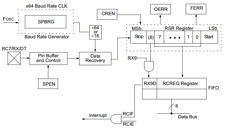
A Brief Description For UART Receiving Process
The data is received on the RX/C7 physical pin and drives the data recovery block. The data recovery block is actually a high-speed shifter, operating at x16 times the baud rate. Whereas the main receiver serial shifter operates at the bit rate or at FOSC.
Once the Asynchronous mode is selected, reception is enabled by setting bit CREN. The heart of the receiver is the Receive Serial Shift Register RSR. After sampling the Stop bit, the received data frame in the RSR is transferred to the RCREG register (if it is empty). If the transfer is complete, the flag bit, RCIF, is set. The actual interrupt can be enabled/disabled by setting/clearing the enable bit, RCIE. Flag bit RCIF is a read-only bit which is cleared by the hardware. It is cleared when the RCREG register has been read and is empty. The RCREG is a double-buffered register which means it’s a two-level deep FIFO.
Physical Layer Standards
There are actually many different standards that utilize the same UART protocol previously described. Such as: TTL level UART, RS-232, RS-422, RS-485, etc. We’ll only discuss both the TTL-level UART and RS-232 in this sub-section of our tutorial. However, we are more interested in the TTL-Level supported by the microcontrollers which we’re aiming to (program) drive hereafter in this tutorial.
TTL-Level UART
The majority of microcontroller chips with UART serial communication modules do use TTL (Transistor-transistor Logic) level UART. Actually, it’s the simplest form of UART. Both logic-1 and logic-0 are represented by 5V and 0V respectively.
| Logic Level | Logic-1 (High) | Logic-0 (Low) |
| Voltage | 5v | 0v |
The TTL-level UART is more likely to be used in the communications between MCUs, modules, sensors, and ICs. It requires only 2-wires for the full-duplex communication and it’s connected as shown in the following diagram.
RS-232 UART
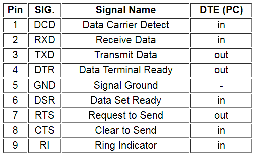
RS-232 (Recommended Standard 232) is a standard for serial binary data signals connecting between a Data Terminal Equipment (DTE) and a Data Communication Equipment (DCE). It is commonly used in computers’ old-school serial ports. The major differences between TTL level UART and RS-232 include the voltage-level. The digital signals in RS-232 are ±3 to – ±15V, and signals near 0V aren’t detected anyway.
| Logic Level | Logic-1 (High) | Logic-0 (Low) |
| Voltage | +3 to +15v | -3 to -15v |
The RS-232 also has a few more pins than the TTL-level UARTs, specifically designed for the communication between PCs and Modems in the past. The pinout of the DB-9 and their functions are shown down below.
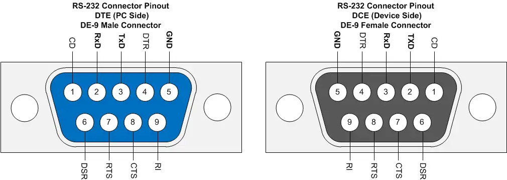
We’re more interested in the standard TTL-Level UART modules available in our microcontroller, but you should also know the basics of RS-232 standards. Maybe in the future, I’ll consider creating a dedicated tutorial for this. For now, let’s continue our introduction to UARTs.
Advantages Of UART Serial Communication
- Only two wires are required for a full-duplex data transmission (excluding the power lines).
- The structure of the data packet can be changed with coordination between both ends.
- No need for a serial clock signal (in asynchronous mode).
- Parity bit provides a hardware-level error detection.
- Well-documented and widely-used protocol.
- Relatively easy to set-up and run.
Disadvantages Of UART Serial Communication
- Speed for data transfer is less compared to parallel communication or even USARTs.
- The baud rates of each UART must be the same within a limited small error margin.
- The size of the data frame is limited to a maximum value of 9-Bits.
- Doesn’t support multiple slaves or multiple masters capability.
USART Module In PIC MCUs
Description
The Universal Synchronous Asynchronous Receiver Transmitter (USART) module is one of the two serial I/O modules. (USART is also known as a Serial Communications Interface or SCI.) The USART can be configured as a full-duplex asynchronous system that can communicate with peripheral devices, such as CRT terminals and personal computers, or it can be configured as a half-duplex synchronous system that can communicate with sensors, modules, etc.
The USART module can be configured to operate in one of the following modes:
• Asynchronous (full-duplex)
• Synchronous – Master (half-duplex)
• Synchronous – Slave (half-duplex)
Baud Rate Generator (BRG)
The BRG supports both the Asynchronous and Synchronous modes of the USART. It is a dedicated 8-bit baud rate generator. The SPBRG register controls the period of a free running 8-bit timer. In Asynchronous mode, bit BRGH also controls the baud rate. In Synchronous mode, bit BRGH is ignored. Down below is the formula for computation of the baud rate for different USART modes which only apply in Master mode (internal clock).
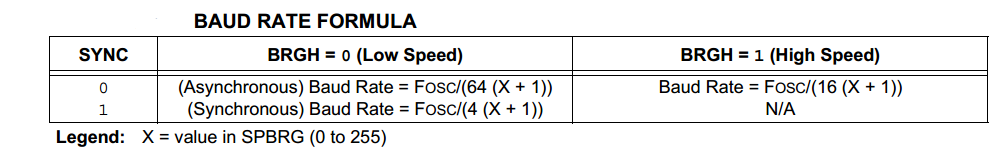
Given the desired baud rate and FOSC, the nearest integer value for the SPBRG register can be calculated using the formula previously shown. From this, the error in baud rate can be determined. It may be advantageous to use the high baud rate (BRGH = 1) even for slower baud clocks. This is because the FOSC/(16 (X + 1)) equation can reduce the baud rate error in some cases.
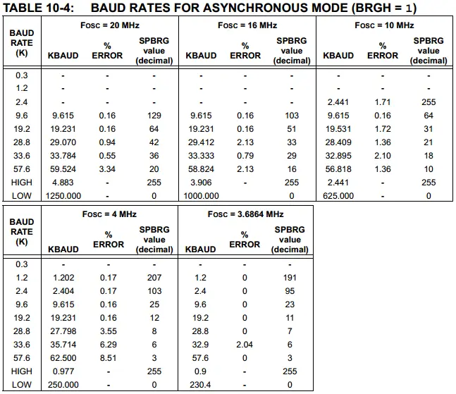
You can refer to table 10-4 in the datasheet for some example values for Baud Rate VS multiple values for Fosc (in Asynchronous mode, BRGH=1). Here is a snapshot for this table.
Note That: Writing a new value to the SPBRG register causes the BRG timer to be reset (or cleared). This ensures the BRG does not wait for a timer overflow before outputting the new baud rate.
UART SFR Registers
Here is a list of the SFRs (special function registers) involved in the UART data transmission/reception.
- TXSTA – Transmitter status and control register
- RCSTA – Receiver status and control register
- SPBRG – Baud rate generator register
- TXREG – Transmitter Buffer Register
- RCREG – Receiver Buffer Register
How To Configure The UART Transmitter?
In this section, we’ll be focusing on the process of configuring a PIC microcontroller to work as a UART Asynchronous Transmitter. Enough of general information about UART! let’s get our microcontroller to work as a serial UART transmitter!
The Mechanics Of UART Transmission
The UART transmits and receives the LSB first. The transmitter and receiver are functionally independent but use the same data format and baud rate. The baud rate generator produces a clock, either x16 or x64 of the bit shift rate, depending on bit BRGH. Parity is not supported by the hardware but can be implemented in software (and stored as the ninth data bit). Asynchronous mode is stopped during Sleep. Asynchronous mode is selected by clearing bit SYNC. The UART Asynchronous module consists of the following important elements:
• Baud Rate Generator
• Sampling Circuit
• Asynchronous Transmitter
• Asynchronous Receiver
The heart of the transmitter is the Transmit (Serial) Shift Register TSR. The shift register obtains its data from the Read/Write Transmit Buffer, TXREG. The TXREG register is loaded with data in software. The TSR register is not loaded until the Stop bit has been transmitted from the previous loading process. As soon as the Stop bit is transmitted, the TSR is loaded with new data frame from the TXREG register (if available). Once the TXREG register transfers the data to the TSR register (occurs in one TCY), the TXREG register is empty and flag bit, TXIF, is set. This interrupt can be enabled/disabled by setting/clearing enable bit, TXIE.
Flag bit TXIF will be set regardless of the state of enable bit TXIE and cannot be cleared in software. It will reset only when new data is loaded into the TXREG register. While flag bit TXIF indicates the status of the TXREG register, another bit, TRMT, shows the status of the TSR register. Status bit TRMT is a read-only bit which is set when the TSR register is empty. No interrupt logic is tied to this bit so the programmer has to poll this bit in software to determine if the TSR register is empty or not.
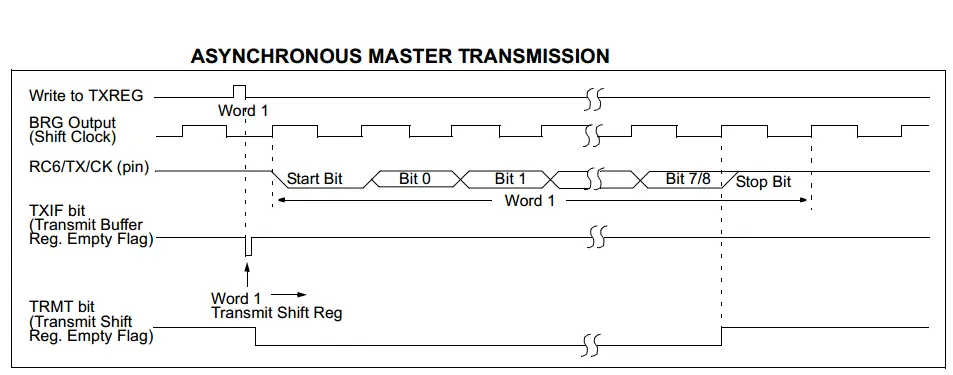
Transmission is enabled by setting enable bit, TXEN. The actual transmission will not occur until the TXREG register has been loaded with data and the Baud Rate Generator (BRG) has produced a shift clock as in the following diagram.
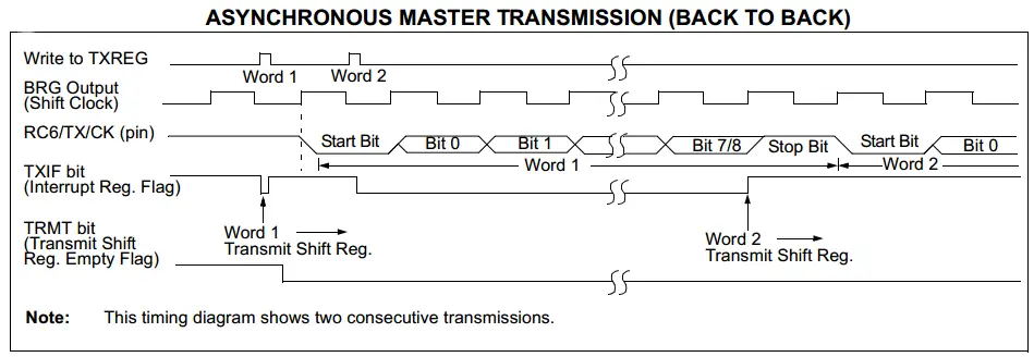
The transmission can also be started by first loading the TXREG register and then setting enable bit TXEN. Normally, when a transmission is first started, the TSR register is empty. At that point, transfer to the TXREG register will result in an immediate transfer to TSR, resulting in an empty TXREG. A back-to-back transfer is thus possible, which means we can send consecutive data frames continuously as shown in the following diagram.
Clearing the enable bit TXEN during a transmission will cause the transmission to be aborted and will reset the transmitter. As a result, the TX/RC6 pin will revert to High-impedance.
If it feels overwhelming, stay cool. It really does! Each of us has been at the same point and yes! it felt overwhelming. Take the time to understand each step of the mechanics.
Down below are the exact brief steps that you should follow to configure your UART Asynchronous Transmitter, even without looking up any diagram in the datasheet. However, you should consider doing so sooner or later at some point.
Steps For Configuring The UART Transmitter
- Initialize the SPBRG register for the appropriate baud rate. If a high-speed baud rate is desired, set the bit BRGH.
- Enable the asynchronous serial port by clearing bit SYNC and setting bit SPEN.
- Bits TRISC<7:6> have to be set in order to configure pins RC6/TX/CK and RC7/RX/DT as the Universal Synchronous Asynchronous Receiver Transmitter.
- If interrupts are desired, then set the enable bit TXIE.
- If the 9-bit transmission is desired, then set transmit bit TX9.
- Enable the transmission by setting bit TXEN, which will also set bit TXIF.
- If the 9-bit transmission is selected, the 9th bit should be loaded in bit TX9D.
- Load data to the TXREG register (this step automatically starts the transmission).
- If using interrupts, ensure that GIE and PEIE (bits 7 and 6) of the INTCON register are set.
Implementing UART Transmitter Driver Firmware
Step1 write to the SPBRG register in order to set the desired baud rate
Using the High-Speed baud rate even for low speeds is advantageous due to the fact that the error percentage will be significantly smaller. Doing so requires setting the BRGH bit.
Let’s say our system is running @ 4MHz Fosc and it’s desired to generate 9600bps baud rate. Using the baud rate formula shown earlier.
![]()
Solving for x (the value to be written to the SPBRG register), it turns out to be
x = 25 (approximately)
Therefore, the c-code for this step is as follows
|
1 2 |
BRGH = 1; // Set For High-Speed Baud Rate SPBRG = 25; // Set The Baud Rate To Be 9600 bps |
Step2 Enable The Asynchronous Serial Port
|
1 2 3 |
// Enable The Ascynchronous Serial Port SYNC = 0; SPEN = 1; |
We won’t be using interrupts for UART transmitter in this tutorial, so I won’t be going through any interrupt activation steps.
Step3 Set The RX-TX Pins Data Direction
|
1 2 3 |
// Set The RX-TX Pins to be in UART mode (not io) TRISC6 = 1; // As stated in the datasheet TRISC7 = 1; // As stated in the datasheet |
Step4 Enable The UART Transmission Process
This is done by setting the TXEN bit.
|
1 |
TXEN = 1; // Enable UART Transmission |
Step5 Load The Data To TXREG
Load the data to be transmitted to the TXREG register.
|
1 |
TXREG = data; // Load the data to the transmitter buffer |
Mission Complete! Transmission is done!
UART Transmitter Full Code Listing
You can easily use those 3-functions within your code. Calling the UART_TX_Init() procedure will configure the UART transmitter for you. Then, calling the UART_Write(data) will shift-out the data frame from your transmitter to the receiving end.
|
1 2 3 4 5 6 7 8 9 10 11 12 13 14 15 16 17 18 19 20 21 22 23 24 |
void UART_TX_Init(void) { BRGH = 1; // Set For High-Speed Baud Rate SPBRG = 25; // Set The Baud Rate To Be 9600 bps //--[ Enable The Ascynchronous Serial Port ]-- SYNC = 0; SPEN = 1; //--[ Set The RX-TX Pins to be in UART mode (not io) ]-- TRISC6 = 1; // As stated in the datasheet TRISC7 = 1; // As stated in the datasheet TXEN = 1; // Enable UART Transmission } void UART_Write(uint8_t data) { while(!TRMT); TXREG = data; } uint8_t UART_TX_Empty() { // Check the output (transmitter) buffer emptiness return TRMT; } |
How To Configure The UART Receiver?
In this section, we’ll be discussing the process of configuring a PIC microcontroller to work as a UART receiver. Let’s get our microcontroller to work as a serial UART receiver.
The Mechanics Of UART Reception
The data is received on the RX/C7 physical pin and drives the data recovery block. The data recovery block is actually a high-speed shifter, operating at x16 times the baud rate. Whereas the main receiver serial shifter operates at the bit rate or at FOSC.
Once the Asynchronous mode is selected, reception is enabled by setting bit CREN. The heart of the receiver is the Receive Serial Shift Register RSR. After sampling the Stop bit, the received data frame in the RSR is transferred to the RCREG register (if it is empty). If the transfer is complete, the flag bit, RCIF, is set. The actual interrupt can be enabled/disabled by setting/clearing the enable bit, RCIE. Flag bit RCIF is a read-only bit which is cleared by the hardware. It is cleared when the RCREG register has been read and is empty. The RCREG is a double-buffered register which means it’s a two-level deep FIFO.
Down below are the exact brief steps that you should follow to configure your UART Asynchronous Receiver, even without looking up any diagram in the datasheet. However, you should consider doing so sooner or later at some point.
Steps For Configuring The UART Receiver
- Initialize the SPBRG register for the appropriate baud rate. If a high-speed baud rate is desired, set bit BRGH.
- Enable the asynchronous serial port by clearing bit SYNC and setting bit SPEN.
- Bits TRISC<7:6> have to be set in order to configure pins RC6/TX/CK and RC7/RX/DT as the Universal Synchronous Asynchronous Receiver Transmitter.
- If interrupts are desired, then set enable bit RCIE.
- If a 9-Bit reception is desired, then set bit RX9.
- Enable the reception by setting bit CREN.
- Flag bit RCIF will be set when reception is complete and an interrupt will be generated if enable bit RCIE is set.
- Read the RCSTA register to get the ninth bit (if enabled) and determine if any error occurred during reception.
- Read the 8-bit received data by reading the RCREG register.
- If any error occurred, clear the error by clearing enable bit CREN.
- If using interrupts, ensure that GIE and PEIE (bits 7 and 6) of the INTCON register are set.
Implementing UART Receiver Driver Firmware
Step1 write to the SPBRG register in order to set the desired baud rate
The same as the UART transmitter which runs @ 4MHz and the desired baud rate must be 9600 as well. Hence, the c-code for this step is as follows
|
1 2 |
BRGH = 1; // Set For High-Speed Baud Rate SPBRG = 25; // Set The Baud Rate To Be 9600 bps |
Step2 Enable the asynchronous serial port
|
1 2 3 |
// Enable The Ascynchronous Serial Port SYNC = 0; SPEN = 1; |
We won’t be using interrupts for UART transmitter in this tutorial, so I won’t be going through any interrupt activation steps.
Step3 Set The RX-TX Pins Data Direction
|
1 2 3 |
// Set The RX-TX Pins to be in UART mode (not io) TRISC6 = 1; // As stated in the datasheet TRISC7 = 1; // As stated in the datasheet |
We’ll be using UART Data Reception interrupt to signal our microcontroller each time a data frame arrives at the UART receiving buffer. The ISR routine should read out the data from the buffer and store it in the respective (safe) place. This action will automatically set the receiver to be ready for a consecutive data reception. However, we (the programmers) should not forget clearing the interrupt flag bit in software!
Step4 Setup UART Receiving Interrupt
|
1 2 3 |
RCIE = 1; // UART Receving Interrupt Enable Bit PEIE = 1; // Peripherals Interrupt Enable Bit GIE = 1; // Global Interrupt Enable Bit |
Step5 Enable UART Data Reception
This is done by setting the CREN bit.
|
1 |
CREN = 1; // Enable Data Reception |
Step6 Read The Received Data Upon Reception
This is actually done within the ISR function by reading the RCREG (the receiver buffer register).
|
1 2 3 4 5 6 7 8 |
void interrupt ISR (void) { if (RCIF == 1) { Destination = RCREG; // Read The Received Data Buffer RCIF = 0; // Clear The Flag } } |
However, you can still poll the RXREG buffer register within your main code. Almost in every situation, you’ll be missing most of the received data using this way! But, for limited applications where data received via UART is coming at a very low rate (maybe 10-Bytes/second or whatever), then you might be using the following simple UART_Read() function and calling it from your main routine.
|
1 2 3 4 5 |
uint8_t UART_Read() { while(!RCIF); return RCREG; } |
Mission Complete! Reception Accomplished!
UART Receiver Full Code Listing
You can easily use those functions within your code. Calling the UART_RX_Init() procedure will configure the UART receiver for you. Then, calling the UART_Read() will return the data frame from your receiver buffer register.
|
1 2 3 4 5 6 7 8 9 10 11 12 13 14 15 16 17 18 19 20 21 22 23 24 25 26 27 28 29 30 31 32 33 34 35 36 |
void UART_RX_Init() { BRGH = 1; // Set For High-Speed Baud Rate SPBRG = 25; // Set The Baud Rate To Be 9600 bps // Enable The Ascynchronous Serial Port SYNC = 0; SPEN = 1; // Set The RX-TX Pins to be in UART mode (not io) TRISC6 = 1; // As stated in the datasheet TRISC7 = 1; // As stated in the datasheet //--[ Enable UART Receiving Interrupts ]-- RCIE = 1; // UART Receving Interrupt Enable Bit PEIE = 1; // Peripherals Interrupt Enable Bit GIE = 1; // Global Interrupt Enable Bit //------------------ CREN = 1; // Enable Data Continous Reception } // You can call this from your main routine uint8_t UART_Read() { while(!RCIF); return RCREG; } // You can include this handler within your ISR void interrupt ISR (void) { if (RCIF == 1) { Destination = RCREG; // Read The Received Data Buffer RCIF = 0; // Clear The Flag } } |
µC-To-µC UART Communication – LAB
| Lab Name | UART Basic Communication |
| Lab Number | 16 |
| Lab Level | Intermediate |
| Lab Objectives | Learn how to create a serial communication interface between 2 microcontrollers using UART Protocol. We’ll send specific data frames from a transmitter MCU and receive it back with another one then double-check the data correctness and validate the communication process. |
1. Coding
Open the MPLAB IDE and create a couple of new projects name them “UART_TX” and “UART_RX” for master and slave MCUs respectively. If you have some issues doing so, you can always refer to the previous tutorial using the link below.

Set the configuration bits to match the generic setting which we’ve stated earlier. And if you also find troubles creating this file, you can always refer to the previous tutorial using the link below.
Now, open the main.c file of each project and let’s start developing the firmware for our project.
1. UART Transmitter (Master)
[ Transmitter Firmware ]
Our task is to take 3 inputs from the user using 3 push buttons to do the following tasks:
Button1: increment the data value
Button2: decrement the data value
Button3: send the current data frame via UART @ 9600bps
We’ll use PORTD to display the current data value for the user. And 3 input pins of PORTB. Obviously, we’ll also configure our microcontroller to operate as a transmitter as we’ve seen earlier in this tutorial. Here is the full code listing for the transmitter MCU chip.
|
1 2 3 4 5 6 7 8 9 10 11 12 13 14 15 16 17 18 19 20 21 22 23 24 25 26 27 28 29 30 31 32 33 34 35 36 37 38 39 40 41 42 43 44 45 46 47 48 49 50 51 52 53 54 55 56 57 58 59 60 61 62 63 64 65 66 67 68 69 70 71 72 73 74 |
/* * LAB Number: 15 * LAB Name: UART_Basic_Communication (Master Code) * Author: Khaled Magdy * For More Information Visit My Website @ DeepBlueMbedded.com * */ #include <xc.h> #include <stdint.h> #include "config.h" #define _XTAL_FREQ 4000000 //-------------------------------- // IO Pins Defines (Mappings) #define UP RB0 #define Down RB1 #define Send RB2 //-------------------------------- // Functions Declarations void UART_TX_Init(void); void UART_Write(uint8_t); //-------------------------------- // Main Routine void main(void) { //--[ Peripherals & IO Configurations ]-- UART_TX_Init(); // Initialize The UART in Master Mode @ 9600bps uint8_t Data = 0; // The Data Byte TRISB = 0x07; // RB0, RB1 & RB2 Are Input Pins (Push Buttons) TRISD = 0x00; // Output Port (4-Pins) PORTD = 0x00; // Initially OFF //--------------------------- while(1) { if (UP) // Increment The Data Value { Data++; __delay_ms(250); } if (Down) // Decrement The Data Value { Data--; __delay_ms(250); } if (Send) // Send The Current Data Value Via UART { UART_Write(Data); __delay_ms(250); } PORTD = Data; // Display The Current Data Value @ PORTD } return; } //-------------------------------- // Functions Definitions void UART_TX_Init(void) { BRGH = 1; // Set For High-Speed Baud Rate SPBRG = 25; // Set The Baud Rate To Be 9600 bps //--[ Enable The Ascynchronous Serial Port ]-- SYNC = 0; SPEN = 1; //--[ Set The RX-TX Pins to be in UART mode (not io) ]-- TRISC6 = 1; // As stated in the datasheet TRISC7 = 1; // As stated in the datasheet TXEN = 1; // Enable UART Transmission } void UART_Write(uint8_t data) { while(!TRMT); TXREG = data; } |
2. UART Receiver (Slave)
[ Receiver Firmware ]
Our task is to set up the UART module to operate in slave mode @ 9600bps and enable the UART data reception interrupt. Within the ISR handler, we should read the received byte of data and latch it out to PORTB with some LEDs for data inspection. And here is the full code listing for the receiver MCU chip.
|
1 2 3 4 5 6 7 8 9 10 11 12 13 14 15 16 17 18 19 20 21 22 23 24 25 26 27 28 29 30 31 32 33 34 35 36 37 38 39 40 41 42 43 44 45 46 47 48 49 50 51 52 53 54 55 56 57 58 59 60 61 62 63 |
/* * LAB Number: 15 * LAB Name: UART_Basic_Communication (Slave Code) * Author: Khaled Magdy * For More Information Visit My Website @ DeepBlueMbedded.com * */ #include <xc.h> #include <stdint.h> #include "config.h" #define _XTAL_FREQ 4000000 //-------------------------------- // Functions Declarations void UART_RX_Init(void); uint8_t UART_Read(void); // Globals uint8_t UART_Buffer = 0; //-------------------------------- // Main Routine void main(void) { //--[ Peripherals & IO Configurations ]-- UART_RX_Init(); // Initialize The UART in Master Mode @ 9600bps TRISB = 0x00; // Output Port (4-Pins) PORTB = 0x00; // Initially OFF //--------------------------- while(1) { // Stay Idle, Everything is handled in the ISR ! } return; } //-------------------------------- // Functions Definitions void UART_RX_Init() { BRGH = 1; // Set For High-Speed Baud Rate SPBRG = 25; // Set The Baud Rate To Be 9600 bps // Enable The Ascynchronous Serial Port SYNC = 0; SPEN = 1; // Set The RX-TX Pins to be in UART mode (not io) TRISC6 = 1; // As stated in the datasheet TRISC7 = 1; // As stated in the datasheet //--[ Enable UART Receiving Interrupts ]-- RCIE = 1; // UART Receving Interrupt Enable Bit PEIE = 1; // Peripherals Interrupt Enable Bit GIE = 1; // Global Interrupt Enable Bit //------------------ CREN = 1; // Enable Data Continous Reception } void interrupt ISR (void) { if (RCIF == 1) { UART_Buffer = RCREG; // Read The Received Data Buffer PORTB = UART_Buffer; // Display The Received Data On LEDs RCIF = 0; // Clear The Flag } } |
And We’re Done With The Firmware! Cross Your Fingers! And Hit The Compile Button!
2. Simulation
Create the simulation project on your simulator and connect your circuitry as shown in the schematic diagram down below. Add the hex code to the respective microcontroller chip. The receiver code to the receiver chip and so. Click the run button and test out everything!
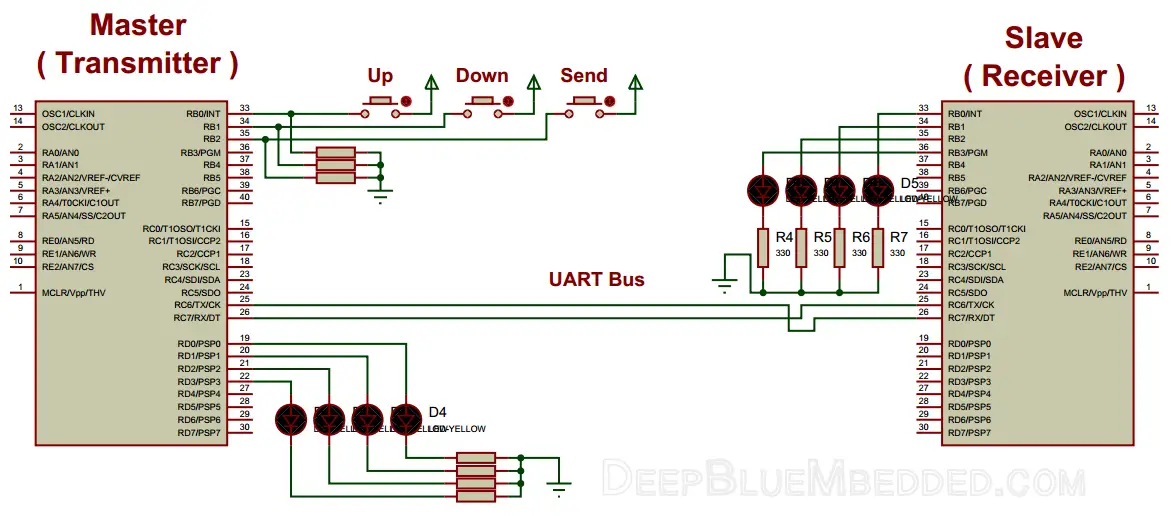
The Running Simulation Test !
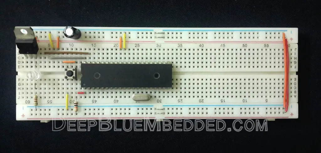
3. Prototyping
If you’ve correctly followed the schematics shown above in the simulation section, you should get your code up and running on a real breadboard flawlessly! However, you should be careful with grounding and RX-TX connections and make sure that you’ve (flashed) uploaded the right code to each chip (Master & Slave).
And here is the final running prototype for this project in case you’re curious.
 |
4. Firmware Template
The previous code listings for this lab despite being fully-functional. It may need a little bit of work to get it working at a different baud rate or at a different clock frequency. That’s why I’ll give you a template for more portable and easier to use firmware for both your transmitter & receiver devices.
Transmitter ( Master Code )
|
1 2 3 4 5 6 7 8 9 10 11 12 13 14 15 16 17 18 19 20 21 22 23 24 25 26 27 28 29 30 31 32 33 34 35 36 37 38 39 40 41 42 43 44 45 46 47 48 49 50 51 52 53 54 55 56 57 58 59 60 61 62 63 64 65 66 67 68 69 |
/* * File Name: UART Firmware Template For (Transmitter / Master) * Author: Khaled Magdy * For More Information Visit My Website @ DeepBlueMbedded.com * */ #include <xc.h> #include <stdint.h> #include "config.h" #define _XTAL_FREQ 4000000 #define Baud 9600 //-------------------------------- // Functions Declarations void UART_TX_Init(void); void UART_Write(uint8_t); void UART_Write_String(char *); //-------------------------------- // Main Routine void main(void) { //--[ Peripherals & IO Configurations ]-- UART_TX_Init(); // Initialize The UART in Master Mode @ 9600bps //--------------------------- while(1) { // Do Whatever You Want ! // ... } return; } //-------------------------------- // Functions Definitions void UART_TX_Init(void) { uint16_t x; x = (_XTAL_FREQ - Baud*64)/(Baud*64); // Low Baud Rate if(x>255) { x = (_XTAL_FREQ - Baud*16)/(Baud*16); // High Baud Rate BRGH = 1; } if (x<=255) { SPBRG = x; //Writing SPBRG Register } //--[ Enable The Ascynchronous Serial Port ]-- SYNC = 0; SPEN = 1; //--[ Set The RX-TX Pins to be in UART mode (not io) ]-- TRISC6 = 1; // As stated in the datasheet TRISC7 = 1; // As stated in the datasheet TXEN = 1; // Enable UART Transmission } void UART_Write(uint8_t data) { while(!TRMT); TXREG = data; } void UART_Write_String(char *text) { uint16_t i; for(i=0;text[i]!='\0';i++) UART_Write(text[i]); } |
Receiver ( Slave Code )
|
1 2 3 4 5 6 7 8 9 10 11 12 13 14 15 16 17 18 19 20 21 22 23 24 25 26 27 28 29 30 31 32 33 34 35 36 37 38 39 40 41 42 43 44 45 46 47 48 49 50 51 52 53 54 55 56 57 58 59 60 61 62 63 64 65 66 67 68 69 70 71 72 73 74 75 76 77 78 79 80 81 82 83 84 |
/* * File Name: UART Firmware Template For (Receiver / Slave) * Author: Khaled Magdy * For More Information Visit My Website @ DeepBlueMbedded.com * */ #include <xc.h> #include <stdint.h> #include "config.h" #define _XTAL_FREQ 4000000 #define Baud 9600 //-------------------------------- // Functions Declarations void UART_RX_Init(void); uint8_t UART_Read(void); void UART_Read_String(uint8_t *); //-------------------------------- // Main Routine void main(void) { //--[ Peripherals & IO Configurations ]-- UART_TX_Init(); // Initialize The UART in Master Mode @ 9600bps //--------------------------- while(1) { // Do Whatever You Want ! // ... } return; } //-------------------------------- // Functions Definitions void UART_RX_Init() { uint16_t x; x = (_XTAL_FREQ - Baud*64)/(Baud*64); // Low Baud Rate if(x>255) { x = (_XTAL_FREQ - Baud*16)/(Baud*16); // High Baud Rate BRGH = 1; } if (x<=255) { SPBRG = x; //Writing SPBRG Register } // Enable The Ascynchronous Serial Port SYNC = 0; SPEN = 1; // Set The RX-TX Pins to be in UART mode (not io) TRISC6 = 1; // As stated in the datasheet TRISC7 = 1; // As stated in the datasheet //--[ Enable UART Receiving Interrupts ]-- RCIE = 1; // UART Receving Interrupt Enable Bit PEIE = 1; // Peripherals Interrupt Enable Bit GIE = 1; // Global Interrupt Enable Bit //------------------ CREN = 1; // Enable Data Continous Reception } uint8_t UART_Read() { while(!RCIF); // Wait Untill a Data Frame is Received return RCREG; } void UART_Read_String(uint8_t *Output, uint16_t length) { uint16_t i; for(int i=0;i<length;i++) Output[i] = UART_Read(); } // You Can Also Use The ISR If You Want To ! void interrupt ISR (void) { if (RCIF == 1) { // Read The RCREG Buffer Register... RCIF = 0; // Clear The Flag } } |
Pro Tips + Concluding Remarks
1
PC Interfacing With Microcontroller
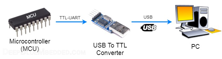
Practically, there do exist many ways to build a PC-MCU interface. However, it’s much easier to use the last one of the following list. We’ll be implementing a PC-controlled embedded system to control some actuators in a dedicated LAB following this tutorial. For now, let’s check the interfacing capabilities (options) to get a microcontroller chip (MCU) to talk to a personal computer (PC) and vice versa.
| TTL-UART To RS-232 Serial (Old Generic Interfacing) |
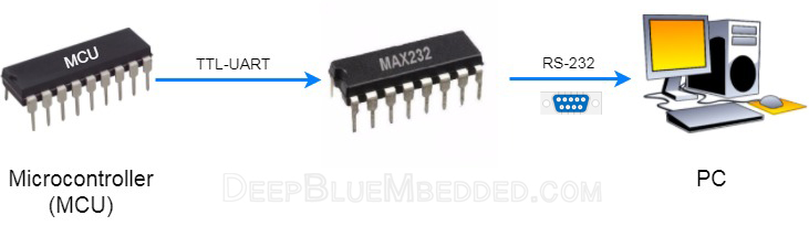 |
| TTL-UART To RS-232 Serial To USB |
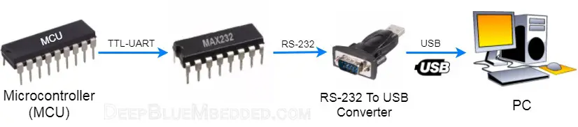 |
| USB-TTL Converter Module |
 |
2
RX-To-TX & TX-To-RX
it’s a very common mistake to have your RX & TX lines wrongly wired. So, please be careful and make sure you’ve connected them correctly. It may take you some time to find out & debug, so be careful in the first place instead.
3
Baud Rate Mismatching
if data is being transmitted at 9600bps Baud rate and being received at a 38400bps. The received data will be a total mess (garbage)! Baud rate must be matched at both ends (Transmitter & Receiver). It’s a rule of thumb in UART serial communication. The maximum allowable shift in baud rates tends to be between (1-2%). So try to generate the exact same baud rate at both ends to avoid mismatching error.
4
Debugging With Virtual Terminal
Communication channels can go crazy in almost any system. Whether it’s a wired or wireless communication. Let’s focus our investigation on the serial UART communication. Imagine a situation in which you’ve got a device A (master) communicating with device B (slave).
Device A: is programmed to send a data frame of (0x05)
Device B: is programmed to latch the received data within the ISR and write it out to PORTB
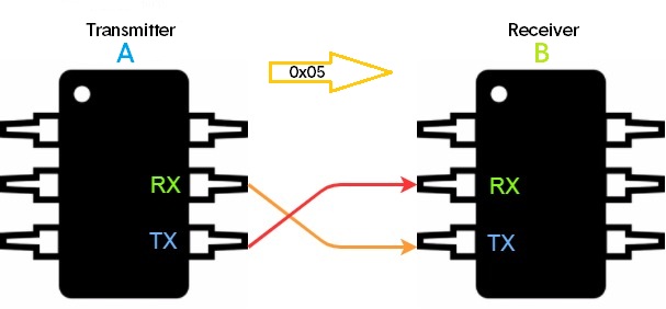
Yet, device B is printing out some random garbage!
The question is, who is the criminal to suspect? is it A? or B? or even the hardware bus on-board?
That’s why it’s kind of a tricky business to debug serial bus communications!
You just can’t decide which firmware has to be fixed. Arbitrarily suspicion & random modifications to either of firmware at A or B can make it more difficult and time-consuming. What I prefer, is to use one of the following methods
- An oscilloscope or Logic Analyzer (inspection)
- Standard virtual serial protocols debugger
I assume that everybody should be familiar with capturing signals on a generic CRO or a Logic analyzer. What I’d really like to point out to are the Virtual Serial Debugger Tools. Just a standard UART receiver/transmitter which you can graphically configure using a GUI. Using it will make your life much more easier, but why?
Well, if you’ve got a standard receiver that is guaranteed to correctly receive each and every data frame, Then you can tell if your UART transmitter (device A) is malfunctioning or not!
Conversely, if you’ve got a standard transmitter that’s is guaranteed to generate and sens specific data frames at a specific baud rate flawlessly, Then you can tell if your UART receiver (Device B) is malfunctioning or not!
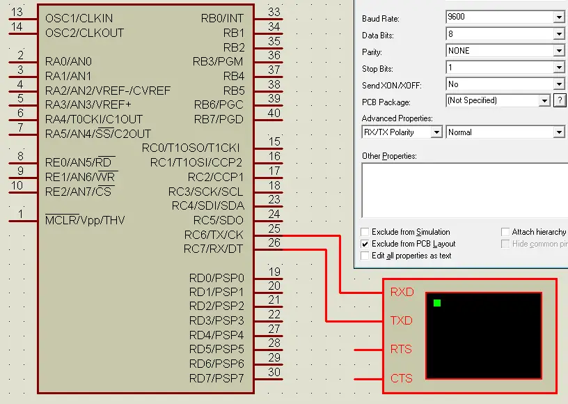
It’s available in proteus ISIS simulator and can be easily configured/connected as you’ve seen in the figure above. Use your own tools and what you personally prefer for debugging. Always be sure that you’re consistently stepping forward toward solving the problem or finding out who is the hiding criminal. And determine where and which changes have to be made!
5
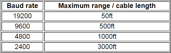
UART Bus Length VS Baud Rate
UART serial buses can go for quite long distances if your application needs so. However, the maximum allowed baud rate gets limited as you go further respectively. It also depends on the hardware implementation (Physical Layer) of the UART protocol itself. We’ll only mention both of the TTL-UART & RS-232 standards.
RS-232
The maximum cable length for RS-232 is 50ft. But in practice, it depends on the baud rate, cable specific capacitance, and ambient noise. The table below contains some rules-of-thumb from experiments done by Texas Instruments years ago.
TTL-UART
TTL level Serial UART only has a 5V swing. Hence, you have to figure out the following 3 things.
1- Cable Resistance: all cables have an impedance that adds up as it goes longer. The longer the cable and higher the resistance, the more the voltage change is detected at one end compared to the other.
2- Cable Capacitance: Highly capacitive wires strongly resist changing from one voltage level to the other. The higher the capacitance of wires, the slower its state changes and more rounded-off the signal becomes. Therefore, the higher the speed and longer the distance, the signal will start to look less like a square wave and more like a noisy sine wave.
3- Noise: it does always exist and assumed to be existent in each environment. And due to the low voltage swing and without differential signaling, it gets harder to communicate farther. However, twisted-pair cables with shielding will greatly help.
Based on that, and my own information/experiments, as there is no sufficient info online in this area. TTL-UART can possibly go 50ft (15m) using a generic UTP Cat 5 cable. As well as the RS-232.
6
Overrun Error
An overrun error occurs when the receiver cannot process the data frame that has just arrived in the buffer before the next one arrives. Various devices have different amounts of buffer space to hold received data. So, let’s focus on our 8-Bit PIC MCU.
During asynchronous UART data reception, It is possible for two bytes of data to be received and transferred to the RCREG FIFO and a third byte to begin shifting to the RSR register. On the detection of the Stop bit of the third byte, if the RCREG register is still full, the Overrun Error bit, OERR, will be set to indicate that an Overrun Error has occurred.
The word in the RSR (the 3rd byte) will be lost. The RCREG register can be read twice to retrieve the two bytes in the FIFO. Overrun bit OERR has to be cleared in software. This is done by resetting the receive logic (CREN is cleared and then set). If bit OERR is set, transfers from the RSR register to the RCREG register are inhibited and no further data will be received. It is, therefore, essential to clear error bit OERR if it is set.
7
Framing Error
A UART receiver will detect a Framing Error when it does not see a stop bit at the expected time after a start bit. As the start bit is used to identify the beginning of an incoming data frame, its timing is a reference for the remaining bits. If the data line is not in the expected state (high) when the “stop” bit is expected (according to the number of data and parity bits for which the UART is set), the UART will signal a framing error. Which means the timing between data bits, start bit, and stop bit is somehow for whatever reason is just messed up! A break condition on the line is also signaled as a framing error.
There exist many reasons for which a framing error may occur such as:
- Baud rate mismatches
- A too long serial data line
- Electrical noise on the serial cable
Framing error bit, FERR, is set if a Stop bit is detected as clear. Bit FERR and the 9th receive bit are buffered the same way as the receive data. Reading the RCREG will load bits RX9D and FERR with new values, therefore, it is essential for the programmer to read the RCSTA register before reading the RCREG register in order not to lose the old FERR and RX9D information.
8
Bus Contention
This happens when you attempt to connect more than 2 devices on the UART serial bus. it’s not allowed to have more than 2 devices on the UART serial bus, as it’s possible to have 2 devices writing data to the same TX line. Which will (at least) cause data corruption at the receiving end. And for worst, the transmitters involved may get damaged (it’s a rare condition, yet mostly protected against).
That’s why they use what’s called (Software Serial UART) in the Arduino ecosystem, in case you’ve got a previous experience with. There’s an FTDI USB-Serial converter connected to the hardware RX/TX pins of the MCU and mostly used for debugging via serial monitor. Hence, connecting any additional serial device (e.g. Bluetooth Module, GPS, etc.) to the same bus will definitely be a problematic act! Eventually, they tend to use software (emulated) serial UART instead. Due to the Bus Contention Error. We’ll briefly address the concept of the emulated-UART hereafter.
9
Software UART (Emulated)
The software can emulate a UART transmitter/receiver module using only some code and consuming a considerable amount of resources specifically CPU’s time and/or a hardware timer. It can extend your available on-chip UARTs or compensate for the lack of a hardware UART at all and to some extents. There is always fundamental limitations and drawbacks for what software can emulate.
All in all, if you’re in a situation where you need an additional UART serial module, you can emulate it using the software. Just in case your demand for a UART is moderately low. But if your application needs extensive UART communication, then you should look for a hardware solution. As overloading your CPU with unnecessarily expensive (in time) software will be a totally inefficient way to go.
| Disclaimer | |||
|
It took me several days to craft this resource on that topic. And most of the information here represents my knowledge and point of view which may have some pitfalls. So, I’ll appreciate any comment, modifications or suggestions to polish this work a little bit more. Some paragraphs, diagrams, tables are copy / pasted from datasheets / technical documentations specifically from Microchip 8-Bit PIC MCUs. Just for the sake of consistency in firmware implementations using these MCU chips. To keep the theoretical side more relevant to practice, I had to do so. It’s protected by fair use act. However, I just wanted to disclaim it for you.
|
|||
| References | |||
|
In case you’re willing to go further. serial port and Microcontrollers: Principles, Circuits, and Source Codes Serial Port Complete: COM Ports, USB Virtual COM Ports, and Ports for Embedded Systems |
|||
| Previous Tutorial | Tutorial 18 | Next Tutorial | |||||
Hello sir,
Its my earliest request to you that please provide ADC tutorial in deep covering every aspects of it.
Sorry for the delay. I’ll be publishing it very soon. A notification will be sent automatically to all subscribers.
Regards ^^
Hello Khaled,
I found your tutorial to be really fascinating and well documented. Thank you so much for this hard work. Please keep it coming on other communication protocols as well.
When you have sometime, can you please explain a bit about DSP and how well can it be implemented using PIC’s?
Thanks so much, dude! I’ll consider doing so in the near future ^^
Dear Khaled Magdy
I uses PIC microcontroller for about 10 years.
Nowadays, my programming all done with PBASIC, compile into HEX file then program it using Universal Programmer.
Please give me some better idea how I can program the PIC by using c++, compile it, and program it.
This enquiry maybe not related to this post, but I hope it benefits all the readers.
Thank you and best regards,
Piau
Do you have the config.h file?
Tutorial #3 in this series of tutorials was dedicated to “How to set the configuration bits”. At the end of it, you’ll find the c-code (directives) to set the configurations for “Generic projects” as used in all of my tutorials. You can copy/paste it in your cofig.h file.
https://deepbluembedded.com/configuration-bits-fuses-for-microcontrollers/
Kudos for this tutorial, man! Keep it up!
The above given code is not working..im using hitech c compiler
It’s written and compiled with XC8 and tested as shown in the video, so everything is ok.
As for Hitech-c, I think it should also work with no problems. If you can tell me more about the specific error you’re getting, maybe i’ll be able to help you a little bit more.
Regards,
Thank you so much Sir for better explanation of the above tutorial .
sir, Can you explain how to implement the UART on FPGA in Verilog .
In the near future, i’ll be explaining fpga hardware design. But for now, you can check nandland.com for amazing fpga tutorials. I’m pretty sure he has done a uart tutorial
hello sir,
why you are not describing the controller part in UART.
can you send me the controller design and baud generator design.
i need to implement uart using only using gates and flipflops.
thank you
regards
Bodasani Harinadha Reddy,
reddyharinadha1@gmail.com
hello, thank you so much sir.
I have a problem related to UART. please email me fadeelfadli@gmail.com.
Hello!
Thank you for sharing the knowledge!
UART tutorial needs a little corrections.
* RS-232 (correct) Logic Levels are: 0 (space) = +3 to +15V, 1 (mark) = -3 to -15V
* RCIF = 0; // Clear The Flag
-> RCIF flag can not be cleared that way, the only way to clear it is to read RCREG.
regards
Thanks for this reply, i was so busy lately but i’ve approved the comment immediately!
I’ll correct these points. Thanks a lot! I really appreciate your contribution
Hello! Thanks for the very informative tutorial.
In the receiving code, it is written RCIF=0;
I remember you have stated that RCIF bit can only be clared by hardware.Then why did you clear this bit by writing 0 to it?
Generally, interrupt flag bits have to be cleared in software after servicing the interrupt request inside the isr.
Did i really state that it’s done in hardware? All in all, if that’s true we won’t have to clear it again in software as you say. Check it out and tell me what you will get!
// Functions Declarations
void UART_RX_Init(void);
uint8_t UART_Read(void);
These lines are from receiver firmware. Were these lines necessary? I mean we have declared the UART_RX_Init() function at the end of the firmware and we have not used UART_Read(void) function at all.
That’s true. If you’ll be using the isr to receive the data so the read function can be removed completely from the entire code file.
On the on the other hand, the init fubction can not be defined without declaring it at the bedinning. Just comment out that line and see the error message from the compiler ????
The block of code at the end is the definition not a declaration. The declaration is still important. Unless you move the function definition block to be above the main. In this case, no declaration is needed.
Hope this helps ^^
Thanks.I understand.
Thanks Khaled for such in depth tutorials. I am using them together with PIC micro-controller datasheet and I always come right. One question though, what is difference between computer science and computer engineering?
Many thanks for a beautifully clear explanation, which I am using to repurpose a PCB with PIC16F877A RS485 input and 4 large 7 segment LEDs as a slave clock. My code fails because I do not understand how to read a string rather than a single character. I expect I need to disable interrupts and reset pointers etc, but an example of receiving strings using the ISR would be very helpful.
well done Khaled Magdy, you did great job , explanation is detailed and beautiful, just keep going
Awesome Tutorial. I have come across a very long way to this. So far best Tutorial. UART explained very elaborately. USART also same, except one caveat:
Master/Slave operation in Synchronous Mode, should had be given some more space.OR another tutorial may be :). Nine Bit Operation with Address Detection would be very useful for those who work in RS485.
Thank you
السلام عليكم ورحمة الله وبركاته
Hi Khaled , hope you are doing well
I have a question about Data recovery in the receiver. you said “The data recovery block is actually a high-speed shifter, operating at x16 times the baud rate” , so what is its role??
Hi Kareem!
Nice question. I didn’t actually illustrate how this x16 times faster sampling rate works or contributes to considering a specific bit to be 1 or 0. However, i beleive that it’s illustrated much better in my STM32 UART Tutorial.
You can also google this subject to get an idea how reading a uart bit 16 times is useful. It helps uart module to make sure that a specific received bit is a 0 or 1. There is a rule for this to happen and you’ll find it in my other article or on google results.
All the best ^^
Greatings Khaled.
First of thank you for this wonderful website.
Just a quick remark:
This did not work for me
TRISC6 = 1;
TRISC7 = 1;
But this did :
TRISC6 = 0; // RC6 should be an output
TRISC7 = 1;
Am I right ?
Thx again. I will go through this whole website ????
Hi Edward. Thx for your feedback. I actually still in doubt if that is the issue in your test setup.
Because it’s stated in the datasheet that both pins should be in input “Hi-Z” mode. That’s why we move 1 to each of both bits TRISC6, 7
I can’t confirm if this is global across all microchip pic mcu parts but as far as i know they are pretty much the same.
HI Khaled
Thank you for your time.
Well you are right, it did not work at first because of my receiver (I’m using an Arduino as second board)
Howerver I tried either TRISC6 as input or output, that works just the same.
But I will follow your saying ????
Right now
PIC-> Arduino works
Arduino -> Does not work yet …
Hi Khaled,
Great body of work, well done and big Thank You, sir.
In the uart tut you refer to your spi tut, however, when I follow the link – Page not Found-
I see that on the Tut homepage, clicking on SPI points to the same link with – Page not Found-
Did you complete the spi tut and where is it located, if you can kindly point me to the link.
Thank you.
Gerhard
sir can u tel me stm 32
Hi
ENG. Khaled
I hope to find you well, i need you help to make one programming for elevator 3 stop using mikroc and proteus .
so am very sorry for interrupted you. thanks too match for your explaining the UART.I wish if this elevator had door and working with UART communication.
thanks for you
regards,