| Previous Tutorial | Tutorial 7 | Next Tutorial | |||||
| Interrupts in PIC Microcontrollers | |||||||
| PIC Microcontrollers Course Home Page ???? | |||||||
In this tutorial, you’ll learn what are interrupts in PIC microcontrollers? How interrupt handling mechanism actually works? And how to respond (service) interrupt signals with C code in MPLAB XC8? You’ll learn all the fundamental mechanics of these processes. You’ll also understand the interrupt logic circuitry within our PIC16F microcontroller platform.
This tutorial includes fundamental theoretical concepts which are substantial for any further investigations. The programming of almost all the upcoming modules involves handling interrupt signals. So it’s extremely important to carefully read this tutorial. Understanding these concepts and mechanics demonstrated herein makes you way more aware of your system. And consequently, limits the probability of getting logical errors.
And never forget, you can always ask any question you want whenever you want. I will read them all and will do my best to help you get everything right. Let’s get started!
[toc]
What Are Interrupts?
Interrupts are basically internal/external signals that suspend the main routine being done/executed. While reading this article, your main routine is “Reading The Tutorial”. This main routine could be interrupted by many sudden events. If your phone suddenly started ringing during the “Reading” process, The main routine “Reading” will be suspended “Interrupted”.
Handling the interrupt signal is mainly dependent on the interrupt source. It could be a phone ring, door bill, or whatever. Each interrupt of those can and will suspend the main routine “Reading”, and require a small portion of your time to handle this interruption. Then you can resume the main routine starting from where you left off.
Using a small bookmark will help you remember where you’ve been at the time of interruption! Which does in line with common sense. You just can’t start reading this article right from the beginning once again, only because you had a sudden phone call (interrupt)!
The situation is similar for microcontrollers or computers in general. Any program being executed by a computer could possibly get suspended by an interrupt signal at any instance of time. You should notice that a computer cannot use a bookmark to help it remember where it left off by the time of receiving the interrupt signal. That’s why there is a specific portion of memory dedicated to this function. Which we’ll discuss in more detail hereafter.
Why We Need Interrupts In Embedded Systems?
Well, an embedded computer (e.g. MCU) is able to respond to any event in two different schemes. The first one is called Polling, which is obviously doing the main routine while checking for the event state from time to time. The second way is by using interrupts, which is obviously doing the main routine all the time until an event occurs which fires an interrupt signal which in turns suspends the main routine. Then the MCU will leave the main program to execute a specific pre-defined code (ISR Handler).
Here is an example to make the difference much clearer. Consider the following main routine in which an MCU is blinking a LED once/2-sec. Executing this loop takes around 2-seconds. Consequently, the MCU can Poll a push button connected to an input pin once/2-second. Pressing this button should command the MCU to (e.g. do something..) which will not happen immediately on the button press event.
On the other hand, an interrupt-driven system will immediately respond to the button press event which fires an interrupt signal that stops the current main routine even if it’s performing a delay macro.
Polling
|
1 2 3 4 5 6 7 8 9 10 11 |
while(1) { LED = 1; __delay_ms(1000); LED = 0; __delay_ms(1000); if (Button == 1) // Polling the button's input pin ! { // Do Something... } } |
Completing the execution of 1-Round in this loop takes roughly 2-seconds of time. In which the MCU checks (polls) the button for a tiny little portion, roughly 1uS. If you’re lucky enough, the MCU will have finished the major 2 delays and will respond to your button press event. But the probability of this case is actually very low. One way to increase the probability of responding to your button press to be 100%, is to hold the button pressed for no less than 2-seconds!
Which is not efficient in almost every situation. Down below is a simulation for the code shown above. Indicating how it’s more unlikely to have your MCU responding to your button press via Polling compared to the following case “Interrupt-Driven”.
Interrupt-Driven
On the other hand, for an interrupt-driven system the main loop will stay the same but with the polling if-statement removed. As shown below
|
1 2 3 4 5 6 7 |
while(1) { LED = 1; __delay_ms(1000); LED = 0; __delay_ms(1000); } |
Now, the button press event will be handled whenever the button is pressed. The MCU will leave off the main loop when an interrupt occurs and head over to the ISR handler which in this example will look like the code shown below
|
1 2 3 4 5 6 7 |
void __interrupt() ISR(void) { if (Button_Interrupt == 1) { // Do Something... } } |
The ISR handler will be immediately executed whenever an interrupt occurs. And the MCU will leave whatever it’s doing to respond to this interrupting event.
Here is a simulation for the codes shown above. Indicating how it’s completely guaranteed to have your MCU responding to your button press immediately via Interrupts. And how low is the responsiveness of your system in case of using the POLLing method.
 |
This point will be re-visited again in much detail in future tutorials. But for now, all you should know that it’s substantially more efficient to use interrupt signals to drive the actions of your system instead of POLLing each device independently from time to time!
Interrupts In Microcontrollers
Hardware designers have done a great job in implementing the concept of interrupts within MCUs. The mechanics of these processes are mainly dependent on the hardware implementation itself which varies from an MCU to another. That’s why we’ll only discuss the interrupt handling mechanism for the PIC16F chip we’re using. But in the next section. For now, we’ll generally discuss interrupts in microcontrollers.
Interrupts could be classified based on the source of the interrupt signal, and also based on the way it’s implemented in memory. Interrupt signals could be generated by hardware or software. Interrupts could be implemented in memory as vectored or non-vectored interrupts. So, let’s classify interrupts in more detail.
Interrupt Sources
Software Interrupts
The programmer (you and me) can purposely fire an interrupt signal whenever he wants using specific instructions (e.g. SWI). This type of interrupt signals is said to be software interrupts. Because the signal’s source is a software instruction. We may not use such a thing during this series of tutorials. However, you should know that many CPUs has specific instructions that generate a software interrupt signal.
Hardware Interrupts
Almost all the peripherals/modules within a microcontroller generate interrupt signals to indicate various events. That’s why this tutorial precedes most of the upcoming modules. Such as Timers, CCP, SPI, UART, I2C, ADC, EEPROM, etc.. All of these modules generate interrupt signals to indicate starting, termination or failure of their current operation.
You should also note that hardware interrupts could be internally or externally triggered. That’s why many authors in our literature call internal modules interrupts “Internal“, and the externally triggered interrupts “External” interrupts. Anyway, hardware interrupts are the most common ones, and it’s our job to efficiently handle them!
Our PIC16F877A MCU has about 15 hardware interrupt sources. We’ll discuss each of them in the respective tutorials hereafter.
Vectored Vs Non-Vectored Interrupts
I bet that you’ve already studied vectors in math/physics class. Well, it’s a kind of related concept here. Vectored quantities are those who have direction. Hence, a vectored interrupt is the one which has a specific pointer pointing to it’s ISR handler. On the other hand, a non-vectored interrupt doesn’t have this feature.
Vectored Interrupts
For vectored interrupts, the CPU knows exactly the address of the ISR handler. The CPU has these addresses pre-defined in memory (interrupt table) in advance. When a vectored interrupt is fired, the interrupting module/device sends its specific vector to the CPU via the data bus. Then, the CPU will perform a look-up in the interrupt table in memory. And then it branches to the ISR handler code associated to the interrupting device and executes it.
Non-Vectored Interrupts
For non-vectored interrupts, the CPU has a hardware fixed address called the interrupt vector. When an interrupt is fired, the CPU will push the PC to the stack. Then it’ll jump to the interrupt vector address and then branches to the ISR handler code. Which is a hard-coded ISR in a specific portion of the memory.
You should have noticed that the CPU has no idea about which device/module that fired this interrupt signal. That’s why it’s our job as programmers to poll the peripherals (check the flags) in order to find out which device requires servicing. Then the CPU will execute the corresponding ISR handler.
Interrupt Handling Mechanism
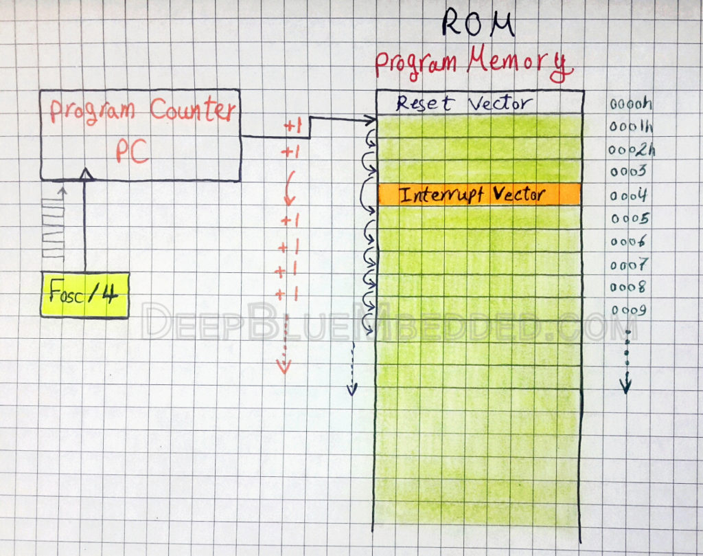
In the microcontroller we’re using (PIC16F877A), the interrupts are non-vectored in memory. So there is a common interrupt vector @ the address 0004h, which is always skipped over while executing the firmware in the program memory. This process is indicated in the figure below
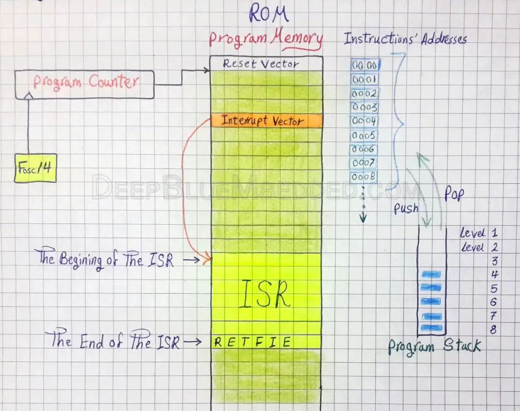
As we previously mentioned, there is no marker to help the CPU keep track of the last instruction was being executed when the interruption occurred. That’s why there is a hardware implemented program stack.
The program stack is basically an 8-levels (8-Registers) structure that holds the addresses of program instructions to be executed. It’s a LIFO structure which means Last-In-First-Out, The last PUSHed address is the first POPed one. Before executing any instruction, its address is PUSHed to the stack.
Whenever an interrupt occurs, the CPU will PUSH the next instruction’s address in the stack. Then the address of the interrupt vector is automatically pushed to the PC so that the CPU branches directly to the ISR handler code to execute it. And when it’s done with the ISR, the CPU will automatically perform the RETFIE instruction to return from the interrupt service routine to the main routine (program). Which obviously POPs the last instruction’s address saved in the stack. Which was the next instruction to be executed before the interruption!
| Note | |||
|
The program stack in our MCU is 8-Levels (Registers) which means it could only keep track of the (next + last-7) executed instructions. When the stack is full (has 8-addresses), the 9th instruction’s address will be PUSHed to over-ride the 1st value. The 2nd address will be overwritten by the 10th address and so on. |
|||
Interrupt Circuitry
The interrupt circuitry is the digital logic circuit that drives the interruption systems within the microcontroller. We use this circuit for both configuring & handling interrupts. The diagram could be easily found in the datasheet (14.11 page 153).
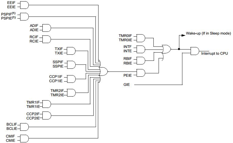
If the binary signal x (could be 0 or 1) is ANDed with 1(High), the result will be the same value of x. On the other hand, if the binary signal x is ANDed with 0(Low), the result will be always 0(Low). That’s why we can model these AND gates in the diagram shown above as ON/OFF switches. And here is a similar (but simpler) diagram
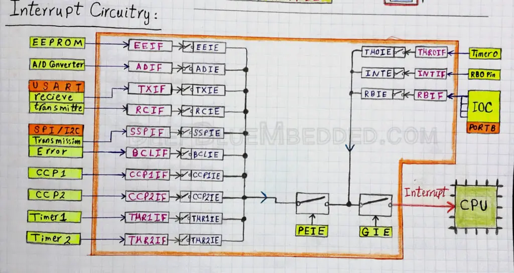
As you may have noticed, there is only one wire coming out of the interrupt circuitry and heading to the CPU. This is because our interrupts are non-vectored so they do share one common interruption signal to the CPU which has no idea about the device that fired the interrupt signal.
Configuring an interrupt source is the first step in working with interrupts. Enabling the ADC interrupt will result in firing an interrupt signal upon each successful ADC conversion process to notify the CPU about it. To enable the ADC interrupt signal you should obviously set all the bits in the way between that module & the CPU!
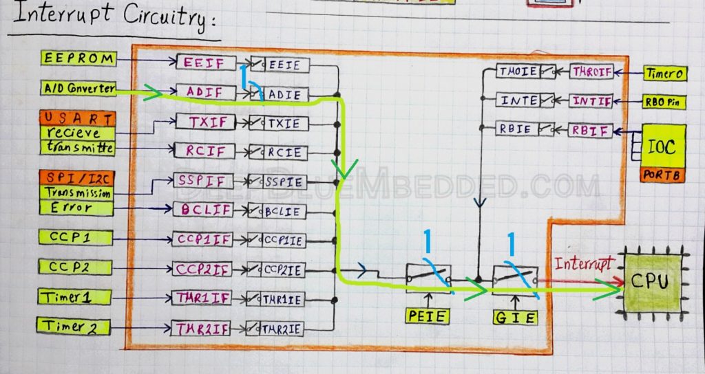
namely, we’ll set the ADCIE, PEIE, and GIE bits. Now, when an ADC conversion is complete. The ADCIF will be set, and the 1(High) signal will reach the CPU to notify it that an interrupt has occurred. But, the CPU now has no idea about which module has generated this signal!
That’s why there are interrupt flag bits, these bits are set upon devices’ interruption respectively. If an ADC conversion is complete, the ADCIF flag bit is set. If Timer1 has reached overflow state, the TMR1IF flag bit is set. And so on.
Upon receiving interrupt signal, the CPU PUSHes the machine state in the stack and branches to the ISR handler. In which we must first poll (check) the Flag Bits, in order to determine the interruption source to service it respectively.
| Pro Tip | |||
|
Interrupt flag bits are automatically set when an interrupt occurs regardless of the corresponding enable bit’s state. Whether it’s enabled or disabled, the flag bit will be set when an interrupt occurs. And the programmer (you and me) should clear these flag bits before enabling interrupts. |
|||
The registers which control the interrupt circuitry are the following 5-Registers
| INTCON | PIE1 | PIE2 | PIR1 | PIR2 |
These registers contain both the interrupt enable bits and the interrupt flag bits. For each interruption source (up to 15). In MPLAB XC8, we’ve bit-fields with the same names found in the datasheet for these bits. So it’s very easy process to set/clear each of these bits in the firmware as we’ll see in future tutorials.
A Perspective On Interrupts Flag Bits
In the previous section, we’ve discussed the interrupt handling mechanism and the role of interrupts’ flag bits in this process. We’ve stated that these bits are set when the respective interrupt event occurs. And as programmers, it’s our job to poll (check) these bits to determine the interruption source device. In order to perform the respective ISR handler code. Finally, it’s our job to clear the flag bit again (to be 0).
| Note | |||
|
You must clear the flag bits (in software) upon handling the interrupt. Forgetting to clear these flags, will lead to insane behavior of the whole system that is hard to debug. |
|||
Writing ISR Handlers
The ISR (interrupt service routine) handler is a portion of your code that goes to a specific chunk of ROM (program memory). In this routine, you’ll first have to check for the interrupt source. Then, handle it respectively. Finally, don’t forget to clear the flag bit of this interruption. We can list these steps as shown below
- Check the interrupt source
- Handle the interrupt
- Clear the flag bit
Let’s consider an example in which you’ll have to do ABC when the Timer1 module overflows, and to do XYZ when an ADC conversion is complete. Configuring the interrupt circuity in order to let these signals reach the CPU will be done by the following code
|
1 2 3 4 |
ADCIE = 1; // ADC Interrupt Enable Bit TMR1IE = 1; // Timer1 Interrupt Enable Bit PEIE = 1; // Peripherals Interrupts Enable Bit GIE = 1; // Global Interrupts Enable Bit |
Your system could possibly be doing whatever tasks in the main loop. Regardless of these tasks, the ISR Handler will be written by following the previous 3-steps as shown below
|
1 2 3 4 5 6 7 8 9 10 11 12 13 |
void __interrupt() ISR(void) { if(TMR1IF == 1) // Check The Flag { // Do ABC... TMR1IF = 0; // Clear The Flag Bit ! } if(ADCIF == 1) // Check The Flag { // Do XYZ... ADCIF = 0; // Clear The Flag Bit ! } } |
Take the time to get familiar with this code, as it’s going to be our standard way of handling interrupts in further tutorials.
The interrupt here is a reserved keyword for indicating that this function is the ISR Handler. The name ISR in the code shown above is the name I usually give to this function. You can name it whatever you want, but keep it relevant and follow a consistent convention. To both help yourself re-read your code listings in the future, and to help your team understand what you’re doing.
| PIC Microcontrollers Course Home Page ???? | |||||||
| Previous Tutorial | Tutorial 7 | Next Tutorial | |||||
What happens if an interrput occurs while the ISR routine is still executing? Would it make a mess?
Nice Question!
When an interrupt signal is fired, the CPU suspends the current operation, saves the current context and switches the control to the interrupt service routine (ISR). The ISR essentially, without your command, will take down the GIE bit. Hence, the CPU can no longer receive an interrupt signal while executing the ISR. However, this operation does not affect any interrupt flag bits.
Example: say the TMR1 has generated an interrupt signal and the CPU started executing the ISR. While executing the ISR, the ADC module has finished an A/D conversion and the ADIF flag bit is set. This will not generate an interrupt because the Global Interrupt Enable bit is cleared (0) by the ISR already.
When the ISR is done executing the TMR1 interrupt handler, The GIE is set back to 1. Now, a new interrupt signal is fired because of the ADIF flag bit is set to 1 after the conversion completion. So, the CPU will execute the ISR once again, specifically, the ADC handler code.
I hope this helps ^^
Kind Regards,
Kindly edit the ISR handler please
from
void interrupt ISR()
to
void __interrupt() ISR(void)
and thank you for your comment on Facebook which clarifies that Microchip has changed the syntax.
From better to best ISA ????
it’s now updated. Thanks for your feedback and you’re always welcomed my dear friend ^^
How does the controller know an interrupt has happened? Is this a default response to any GP input pins?
in old PIC microcontrollers, No it’s not a default response for any GPIO pin. It’s an exclusive feature for only the IRQ pins. Yea, it’s a direct event connected to the interrupt circuitry that’s also connected to the CPU. So, any interrupt event is fired, the CPU knows immediately and starts reading the interrupt FLAG bits to determine the source of the interrupt. Whether it’s an IRQ pin, if so, which one? if not, maybe it’s a UART interrupt, and so on.
In modern PIC microcontrollers, almost all GPIO pins have interrupt capability. And interrupts are vectored. So, when an interrupt event is fired, the CPU knows exactly who is the source, whether it’s a UART, SPI, an IRQ pin, etc.
Hope this helps!
Regrds,
Khaled M.
How long does it take ( in terms of Tcy ) to complete one interrupt call? ( taking into account the time needed from the first call to returning to the normal operation ) Also, how long does it take to jump to ISR?
It’s called interrupt latency. And it’s usually stated in the datasheet because it does vary from one target uC to another.
For performing ADC, should I enable ADC as well as timer interrupt or only Timer interrupt is enough. I am using TMR0 mode 16 bit timer for PIC18F57Q43, and want to print the result using UART. So, what all interrupt should I enable and should I set the priority to it?
Hello, i am new embedded learner and your tutorials are amazing. I have a question regarding the [ ADCIE = 1; // ADC Interrupt Enable Bit] i could not find this from the interrupt logic circuit [there is no ADCIE OR ADCIF]. so could you please let me know how did u find it?
and also i have a personal question, should i finish this pic tutorials, and then starts with the stm32 right? is this is the right path for learning embedded or i should do something external.
Also, i would be grateful if you could simplify and teach control systems, i am a robotics engineer, and i am trying to learn control systems, i am struggling a lot and i don’t know where to learn and what to learn. so if you could make a road map or tutorials for control system that would be great.