How To Generate Software PWM?
(Extending PWM Outputs)
In this article, we’ll discuss the software PWM and how to generate this signal using C code on Microchip 8-Bit microcontrollers. And here is a short demo for the LAB at the end of this article!
1 Pulse Width Modulation (PWM)
1.1 Properties of a PWM Signal
A PWM (pulse width modulated) signal is a digital signal that looks like the one shown in the figure below. The PWM signal is an alternating waveform that keeps changing from 0 to 1 and from 1 to 0. By changing the time in which the signal is High (1), we’ll obtain different values of the duty cycle.
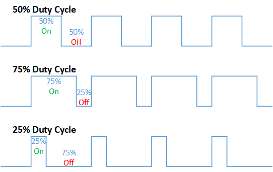
The properties of a typical PWM signal are as follows:
- Frequency: The number of complete cycles of the signal in one second [Hz].
- Duty Cycle: The ratio between the HIGH time to the full period of a single cycle [%].
- Resolution: The Number of the discrete distinct levels that duty cycle can have [Bits].
And we control each of these parameters while configuring a PWM hardware module. And we’ll also do the same while designing a software PWM as we’ll see hereafter in this article.
For CCP modules in Microchip PIC microcontrollers, the typical formulas for each of the previous properties (parameters) of PWM are as shown below.
PWM Frequency (Fpwm)
![]()
Where Tosc = 1/Fosc , T2PS is Timer2 Prescaler Value , PR2 of Timer2 (8-Bit) Register
Duty Cycle
![]()
Note that the DutyCycle is (Time) not a ratio. You should divide it by TPWM to get the duty cycle as a ratio. Also, note that DC value is the 10-Bit value you have to write in order to achieve the desired DutyCycle.
PWM Resolution
![]()
A resolution of 6bits means that the DutyCycle value can range from 0 up to 63 only. A resolution of 8bits means a duty cycle range from 0 to 255. The maximum resolution for the CCP module in PIC MCUs is 10Bits, which means a total of 1024 discrete levels for the duty cycle and that’s a lot indeed!
1.2 Applications For PWM Signals
There is an endless list of situations where PWM is used! Here is a brief short list of PWM typical applications
- Voltage Regulation
- Servo Control
- Solar Charging
- Audio Effects
- LED Brightness Control
- Class D Audio Amplifiers
- Power Control
- and much more…
1.3 How To Generate PWM Signal (Hardware)
Let’s consider a CCP hardware module which you typically find in a Microchip PIC microcontroller. This module can be easily configured to operate in the PWM Mode. Here is the simplified block diagram for the PWM Hardware
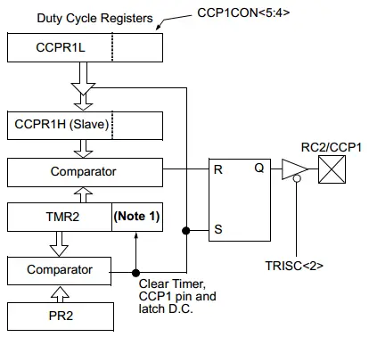
First, the CCP module is set to operate in PWM mode by writing to the CCP1CON register. Then, the required PWM frequency will tell us the PWM time period which we’ll be loading to the PR2 register. Timer2 should be turned ON with the pre-specified Prescaler value. And the duty cycle is set by writing to the [ CCPR1L register & CCP1CON<5:4> Bits ].
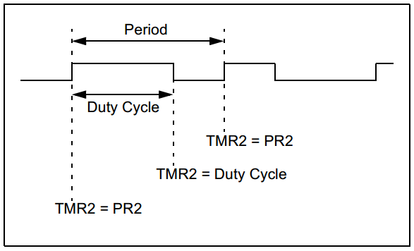
From the PWM Block Diagram, the PR2 value is constantly compared against the TMR2 register until a match occurs which indicates the end of the PWM cycle and the starting of a new cycle. Hence, the value of PR2 determines the time period of each PWM cycle and it consequently provides a mean of controlling the PWM output Frequency!
The CCP1 pin (RC2) is set (High = 1) at the beginning of each cycle. And the DC (duty cycle) 10-Bit value is latched to the [ CCPR1H + 2-Bit internal latches ]. This DC value is constantly compared against the [ TMR2 + 2-Bit Q Clock ]. When a match occurs, the output latch for the CCP1 pin (RC2) is reset (Low = 0). And it stays low till the end of the current PWM cycle.
At the beginning of a new cycle, the output latch is set again to High and so on. Hence, the DC value controls for how long the PWM output pin will be set (High). Hence, the DC 10-Bit value provides a mean for controlling the PWM output Duty Cycle!
1.4 Limitations For Hardware-Generated PWM
I must mention that using the hardware module for PWM generation is the most efficient way to produce a very stable PWM signal with a very high resolution and frequency. It’s far way more efficient than any other method.
However, sometimes, you may need more PWM output pins than the available hardware resources. The hardware PWM outputs maybe only 2 pins! if you need more PWM output, then you should consider designing a software PWM generator. And that’s our next section and the main topic of this article!
2 Software-Generated PWM
2.1 What’s The Software PWM?
It’s a technique of generating PWM output signals without the need for a hardware PWM module within your microcontrollers. It’s commonly used for applications requiring low-frequency low-resolution PWM outputs and many output pins. You can add maybe 10 extra PWM output pins in this way.
2.2 Why We May Need Soft PWM?
We may need software PWM if we’re using a low-end microcontroller with only a couple of PWM output pins. By using software PWM we can extend the PWM outputs up to whatever we want. As long as we’re satisfied with low-frequency low-resolution PWM output.
2.3 What Are The Advantages of Software PWM?
- Easy To Design And implement
- Easy To extend, it’s as easy to add 1 extra PWM pin as it to add 10 more PWMs
- Suitable for servo control and LEDs kind of applications
- No limit for PWM output channels, with soft PWM you can turn all GPIOs into PWM outputs
2.4 What Are The Disadvantages of Software PWM?
- Adds too much of interrupt jitter to your system
- Consumes too much of the CPU time
- The more PWM channels you add, the more jitter starts to creep in
- Limited output frequency ( FPWM )
- Limited duty cycle resolution
3 How To Generate Software PWM
3.1 Designing A Software PWM Generator
In this article, I’ll discuss one way of designing and implementing a software PWM generator. Using a single timer which interrupts the CPU periodically and incrementing a counter variable. By doing software comparisons, we can decide when to drive the PWM output pin high or low. That’s basically the idea of this technique for generating soft PWM. Just follow the procedure below before turning it into firmware (code).
3.2 Procedure
1- Decide on the required resolution (in Bits) for the PWM output. That’s the number of discrete levels of the duty cycle.
2- Decide on the required frequency for the PWM output (FPWM). Note also, TPWM = 1 / FPWM
3- Configure a Timer module to generate a periodic interrupt with a
Time interval equals = TPWM / 2Resolution
You’ll need to perform Timer Preloading in order to achieve exactly the desired time interval.
4- On each timer overflow interrupt, do the following
- Increment a counter variable (e.g. TMR1_C ++ )
- Compare the counter against the DC (duty cycle) value. On match -> { Drive PWM Pin LOW }
- Compare the counter against the Period value. On match -> { Drive PWM Pin HIGH, Reset The Counter }
3.3 Numeric Example
Design a software PWM generator to achieve the following specifications.
- Output Frequency ( FPWM ) = 50 Hz
- PWM Output Channels = 2 output pins
- 100 level of DC <=> Resolution = 6.64 [Bits]
- DC Double-Buffering ( For Low Jitter )
Any may be some extra specifications, such as PWM phase control or dead-time generation. These extra features will be discussed in another article. For now, we’ll see how to perform calculation and implement a software PWM to generate 50Hz signal with 100 level of DC resolution.
1- Resolution = 6.64 Bits <=> 2Resolution = 100 level of DC
2- FPWM = 50Hz => TPWM = 1/50 = 20mSec
3- Setup Timer1 For A Period = 20mSec/100 = 200μs
Here is the timer formula to calculate the perload variable which gives you a desired Tout periodic interrupt signal.
![]()
Let’s insert our system’s parameters to find out the TMR1 initial value (preload). Fosc = 48MHz, Prescaler=1:1, Tout (the desired time interval) = 200μs. The only unknown here is the initial value of TMR1 that has to preloaded in the register. Solve for TMR1, you’ll get 63135.
So, by starting the timer to count from 63135 up to 65535, there will be 2400 timer ticks before it rolls-over and overflow and interrupt the CPU. The time for overflow = Number of Ticks x On Tick Time
= 2400 x (1/12*10-6) = 200μs .. And that’s exactly what we want !
4- On each timer overflow interrupt, do the following
- Increment a counter variable (e.g. TMR1_C ++ )
- Compare the counter against the DC (duty cycle) value. On match -> { Drive PWM Pin LOW }
- Compare the counter against the Period value. On match -> { Drive PWM Pin HIGH, Reset The Counter }
4 Implementation For Software PWM
4.1 Code Listing For 1 PWM Output Channel
|
1 2 3 4 5 6 7 8 9 10 11 12 13 14 15 16 17 18 19 20 21 22 23 24 25 26 27 28 29 30 31 32 33 34 35 36 37 38 39 40 41 42 43 44 45 46 47 48 49 50 51 52 53 54 55 56 57 58 59 60 61 62 63 64 65 66 67 68 69 70 71 72 73 74 75 76 |
/* * File: main.c * Author: Khaled Magdy * Crystal OSC. 4MHz, Fosc = 48MHz * Target MCU: PIC18F2550 * Project Name: Software PWM Generation */ #include <xc.h> #include "config.h" #include <stdint.h> #define _XTAL_FREQ 48000000 #define PWM1_D TRISB1 #define PWM1 RB1 uint16_t TMR1_C; uint8_t PWM1DC = 0; void TMR1_Init(void); void main(void) { PWM1_D = 0; // Set As Output Pin TMR1_Init(); // Setup Timer1 // Write The DC Value You Want And Observe The Output PWM Signal On RB1 Pin // DC Range From 0 To 100 .. As Desired In Our Design Specifications PWM1DC = 75; // Duty Cycle = 75% while(1) { } return; } //-------------------------------------------------------- void __interrupt() ISR() { if(TMR1IF) { TMR1_C++; if(TMR1_C>=PWM1DC) { PWM1 = 0; // Drive PWM Output LOW } if(TMR1_C>=PWM2DC) { PWM2 = 0; // Drive PWM Output LOW } if(TMR1_C==100) { PWM1 = 1; // Drive PWM Output HIGH TMR1_C = 0; // Reset Counter } TMR1IF = 0; TMR1 = 63160; // After Compensation //TMR1 = 63135; // Theoretical Value From Calculations } } //-------------------------------------------------------- void TMR1_Init(void) { // -- [[ Configure Timer1 To Operate In Timer Mode ]] -- // Clear The Timer1 Register. To start counting from 0 TMR1 = 63135; // Choose the local clock source (timer mode) TMR1CS = 0; // Choose the desired prescaler ratio (1:1) T1CKPS0 = 0; T1CKPS1 = 0; // Switch ON Timer1 Module! TMR1ON = 1; // -- [[ Interrupts Configurations ]] -- TMR1IE = 1; // Timer1 Interrupt Enable Bit TMR1IF = 0; // Clear The Interrupt Flag Bit PEIE = 1; // Peripherals Interrupts Enable Bit GIE = 1; // Global Interrupts Enable Bit } |
4.2 Code Listing For 2 PWM Output Channels
|
1 2 3 4 5 6 7 8 9 10 11 12 13 14 15 16 17 18 19 20 21 22 23 24 25 26 27 28 29 30 31 32 33 34 35 36 37 38 39 40 41 42 43 44 45 46 47 48 49 50 51 52 53 54 55 56 57 58 59 60 61 62 63 64 65 66 67 68 69 70 71 72 73 74 75 76 77 78 79 80 81 |
/* * File: main.c * Author: Khaled Magdy * Crystal OSC. 4MHz, Fosc = 48MHz * Target MCU: PIC18F2550 * Project Name: Software PWM Generation */ #include <xc.h> #include "config.h" #include <stdint.h> #define _XTAL_FREQ 48000000 #define PWM1_D TRISB1 #define PWM1 RB1 #define PWM2_D TRISB2 #define PWM2 RB2 uint16_t TMR1_C; uint8_t PWM1DC = 0, PWM2DC = 0; void TMR1_Init(void); void main(void) { PWM1_D = 0; // Set As Output Pin PWM2_D = 0; TMR1_Init(); // Setup Timer1 // Write The DC Value You Want To Each Channel Individually // DC Ranges From 0 up to 100 .. As Desired In Our Design Specs! PWM1DC = 75; PWM2DC = 50; while(1) { } return; } //-------------------------------------------------------- void __interrupt() ISR() { if(TMR1IF) { TMR1_C++; if(TMR1_C>=PWM1DC) { PWM1 = 0; // Drive PWM Output LOW } if(TMR1_C>=PWM2DC) { PWM2 = 0; // Drive PWM Output LOW } if(TMR1_C==100) { PWM1 = 1; // Drive PWM Output HIGH PWM2 = 1; TMR1_C = 0; // Reset Counter } TMR1IF = 0; TMR1 = 63160; // After Compensation //TMR1 = 63135; // Theoretical Value From Calculations } } //-------------------------------------------------------- void TMR1_Init(void) { // -- [[ Configure Timer1 To Operate In Timer Mode ]] -- // Clear The Timer1 Register. To start counting from 0 TMR1 = 63135; // Choose the local clock source (timer mode) TMR1CS = 0; // Choose the desired prescaler ratio (1:1) T1CKPS0 = 0; T1CKPS1 = 0; // Switch ON Timer1 Module! TMR1ON = 1; // -- [[ Interrupts Configurations ]] -- TMR1IE = 1; // Timer1 Interrupt Enable Bit TMR1IF = 0; // Clear The Interrupt Flag Bit PEIE = 1; // Peripherals Interrupts Enable Bit GIE = 1; // Global Interrupts Enable Bit } |
4.3 Replicate This On Your Own!
Now, you can replicate this project on your own. You see how it’s easy to add extra PWM output channels. You can add 2, 4, 10, or even make all GPIO pins to pretend to be PWM outputs!
The steps for calculating and setting the PWM output for a specific frequency, duty cycle, and resolution are also clear right now. Try replicating the project with different values or as needed by your application.
If you need any further help, just drop me a comment below!
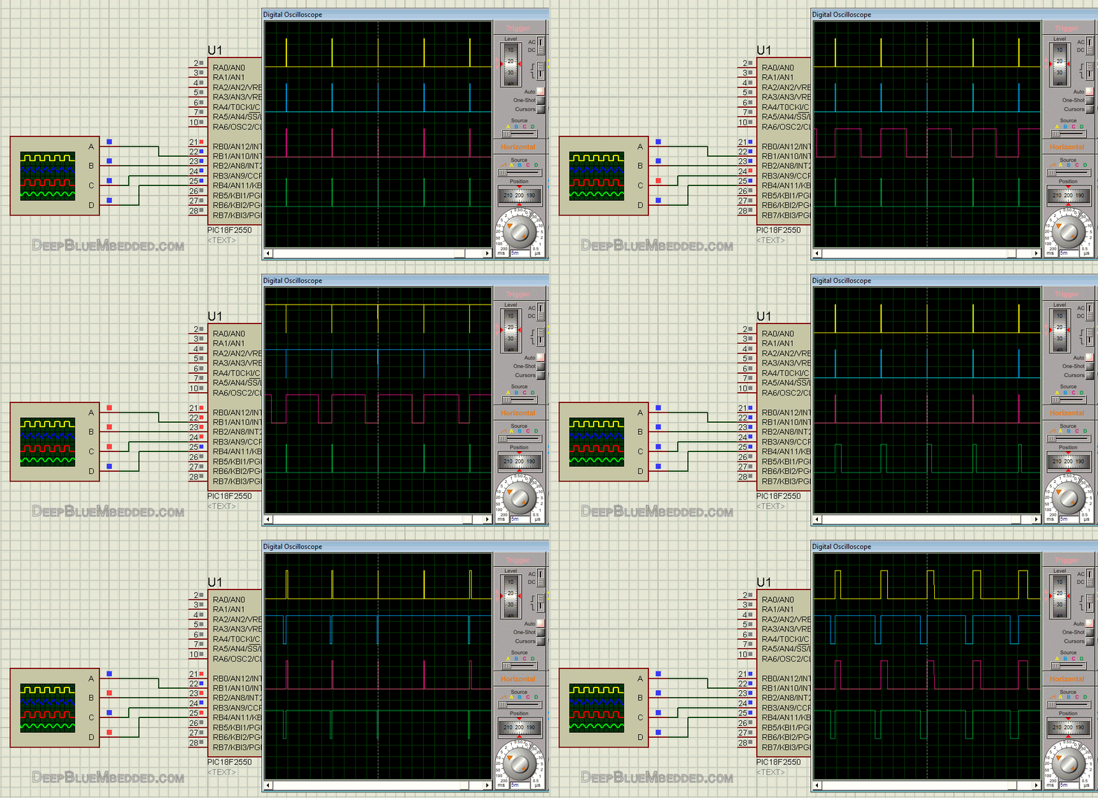
Here is an animation indicating 4 channel software PWM output. Note that pins (RB0, RB1, RB2, RB3) none of them is a CCP pin!
Concluding Remarks
1
Software PWM generation involves adding too much of interrupt jitter to your system. Think about it!
Timer1 overflows once every 200μs. What does this mean?
it means the CPU receives 5000 interrupts per second. And that’s a lot of CPU time consumption!
Well, it gets even worse if you want a higher resolution PWM, or higher output frequency, why?
Here is the Timer Interval Formula = TPWM / 2Resolution = …μs
Higher FPWM means essentially a dramatic decrease in the timer overflow interval which was 200μs. Well, if it becomes say 100μs, that means the CPU will receive 10000 interrupts per second!
High Resolution means essentially a dramatic decrease in timer overflow interval as well.
All in all, demanding a high-resolution high-frequency PWM output is kind of challenging this system and pushing it hard toward its fundamental limits!
2
Software PWM is preferred for low-frequency low-resolution applications. If it’s not the case with you, then you’ll need a real hardware PWM module with sufficient output channels and specs.
Did You Find This Helpful? if yes, why not share it with your community group?!
Support my work by sharing it on socials .. Good luck and regards ^^

Hello
Can you help me, if I have 16 pwm output, which IC & program I must to use?
Thanks
So wonderful, Khaled Magdy!
This topic is so good for limited pwm ouput on PICs.
Thank you very much!
You are really cool, hihi…