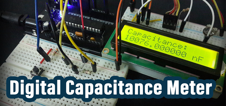
Digital Capacitance Meter
How To Measure A Capacitor With A Microcontroller?
This project shows you how to measure the capacitance of a capacitor with a microcontroller using the analog to digital converter & timer modules. The effective measurement range for the digital capacitance meter we’ll be building is from 1nF to 100uF and the resolution about 0.5nF to a few hundreds at the high end of the range.
You’ll learn all the basics of this interesting topic and how to pick the design parameters to meet your needs. In case you need a higher measurement range or more accuracy or whatever. You’ll get to know which parameters affect which property and how to decide on these trade-offs. Let’s now get started!
Required Components For This Project
| Qty. | Component Name | Buy On Amazon.com |
| 1 | PIC16F877A
or PIC18F2550 |
Add |
| 1 | BreadBoard | Add |
| 1 | Alphanumeric LCD 16×2 | Add |
| 1 | Resistors Kit | Add Add |
| 1 | Capacitors Kit | Add |
| 1 | Jumper Wires Pack | Add Add |
| 1 | LM7805 Voltage Regulator (5v) | Add |
| 1 | 8MHz Crystal Oscillator | Add |
| 1 | PICkit2 or 3 Programmer | Add |
1 Theoretical Background
The working principle of a digital capacitance meter relies on the fact that a capacitor follows a specific equation (formula) during the charging and discharging process. Hence, we can apply a voltage through a known resistor R and monitor how long does it take a capacitor to hit a specific voltage threshold, usually expressed in terms of tau τ which is commonly known as the Time Constant for capacitor charging and discharging (where τ = R x C).
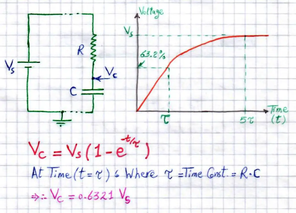
The time it takes a capacitor’s voltage Vc to reach 63.2% from the supply voltage is equal to one time constant (τ which is also equal to R x C). Provided that we’ll be selecting a convenient R for this process, the only unknown to solve for is the capacitance of the inserted capacitor C. And thereafter, it’s a straight-forward process to find it out.
To conclude this, a digital capacitance meter applies a fixed voltage source Vs to the unknown (to be measured) capacitor C through a fixed known resistor R. And it measures the time it takes the voltage across the capacitor Vc to build up from 0v to a specific threshold voltage (i.e at 1τ, 2τ or even fractions like 1.5τ). Assuming a voltage threshold of 0.632Vs, then the measured time is equal to 1τ which is equal to = R x C. Given the value of R, we can solve for C and print out the capacitance value!
2 Using ADC (Method1)
2.1 Basic Idea
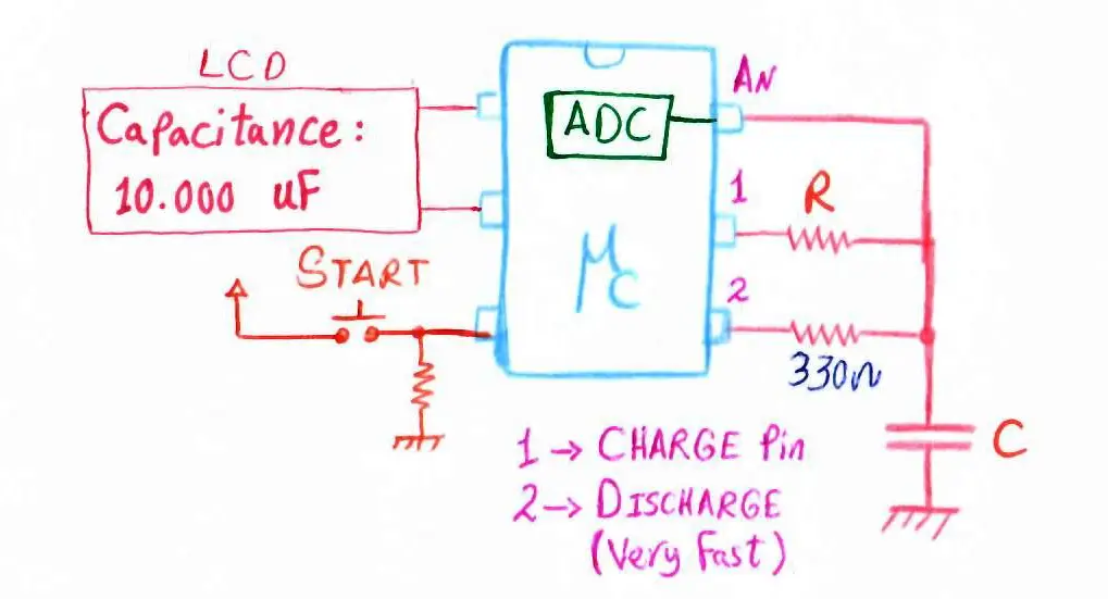
This method utilizes the analog to digital converter (ADC) module inside microcontrollers to measure and monitor the voltage across the unknown capacitor C (to be measured). A couple of io pins are used as well, one for the start measurement input signal of a push button. And another one (pin 1) for charging the capacitor through a fixed value resistance R (usually large enough to get slow charging curve). And the last io pin is pin3 and it’s used to accelerating the discharging process (through small resistor 330Ω). As you might have noticed, the capacitor has to be fully discharged before initiating a measurement process.
When both (pin1 & 2) are LOW, during the discharging phase, the equivalent resistance through which the capacitor is discharging drops dramatically as it’s the parallel net resistance of (330Ω and R). Resulting in an incredibly fast discharging process. You can use only 1 pin however, the same pin1 using only R also for discharging but it’s gonna take sooo long to fully discharge (it’s 5tau = 5τ = 5*R*C).
The Procedure is As Follows
1 The Microcontroller Starts A Timer Module in Timer Mode
2 The ADC will start running in the free-running mode (Auto-Trigger Mode) for continuous successive conversions. Until the measured voltage is larger than or equal to 3.16v (63.2% of 5v).
3 The MCU Stops The Timer And The ADC. Save the time (which is equal to tau τ)
4 Using the time constant we’ve measured in the last step, it’s easy to solve for the capacitance value C using this formula ( τ = R x C ).
These steps are repeated whenever the user presses the START push button.
2.2 Calculations
Picking The Resistor (R)
It doesn’t seem so tricky but it actually is! The value of the R resistor which we’ll be using for charging the unknown capacitor, somehow, controls a variety of other parameters. First of which is the time constant (tau τ = R x C). The smaller R is, the smaller tau is and the faster it’s gonna take the voltage across the capacitor to hit the 63.2% voltage threshold. Well, where is the problem in that?
Obviously, the ADC conversion rate is rather limited by device specifications and moreover, the CPU takes time to service ADC interrupts to compare the current voltage level of Vc whether it’s below 63.2% (3.16v) or not. Hence, we might miss (overshoot) the target voltage threshold and get a wrong measure for tau and consequently wrong capacitance value.
Add to that, a large resistance for R will result in a significant increase in tau and the charing time. Yeilding a very long time required to measure a capacitor. For example, consider R=100kΩ, and you’re willing to measure a capacitor C=1000μF. Do you know how long it’s gonna take to complete the measurement process? Well, it’s also 1tau (which is = R x C). That’s a complete 100 seconds!
For this project, we’ll stick to R=100kΩ. And limiting the C measurement range up to 10μF, at which the measurement time is a maximum of 1 second. That’s acceptable for now!
2.3 Code Snippets
The main routine will be something like this
|
1 2 3 4 5 6 7 8 9 10 11 12 13 14 15 16 17 18 19 20 21 22 23 24 |
void main(void) { IO_Init(); ADC_Init(); LCD_Init(); LCD_Clear(); TMR1_Init(); while(1) { if(Start_Btn) { TMR1 = 0x0000; TMR1_C = 0; Control_PIN = 1; // Charge Through R Discharge_D = 1; // The Small Resistor is disconnected (High-Impedance or Z) // Setting The Pin To Input Makes It High-Impedance (disconnected) TMR1ON = 1; // Start Timer1 GO_nDONE = 1; // Start ADC } // Update The LCD Display Update_Display(); __delay_ms(100); } return; } |
Calculating the time constant (tau) is done in the ISR (interrupts service routine) whenever the ADC finds out that the Vc has crossed the 3.16v voltage threshold. Afterward, the unknown capacitance is easily calculated by dividing the resultant tau by R (the 100k resistor). And the result will be printed on the LCD inside the update_display() function. The full code listing and testing are provided at the end of this article.
3 Using Analog Comparator (Method2)
3.1 Basic Idea
This method utilized the analog comparator module within a microcontroller to perform voltage comparison to monitor the capacitor charging voltage. And when the voltage across the capacitor crosses a specific threshold, the comparator’s output bit changes which fires an interrupt!
We’ll also use a timer module to measure the time between the beginning of the charging process and when a comparator change interrupt occurs. Then we’ll calculate the capacitance using time constant formula as in the first method of ADC.
[ Further Explanation For This Method Will Be in Another Article .. Coming Soon ]
4 Implementing A Capacitance Meter System
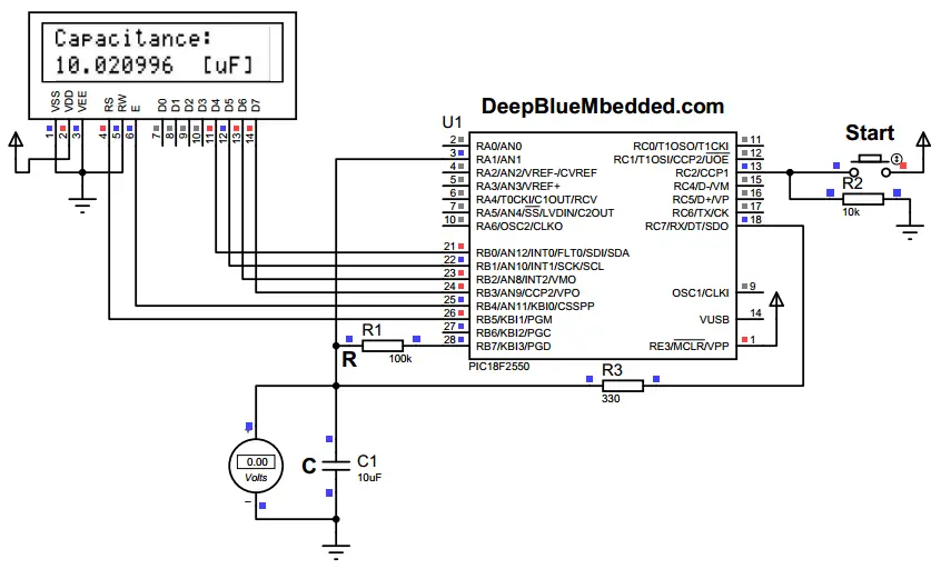
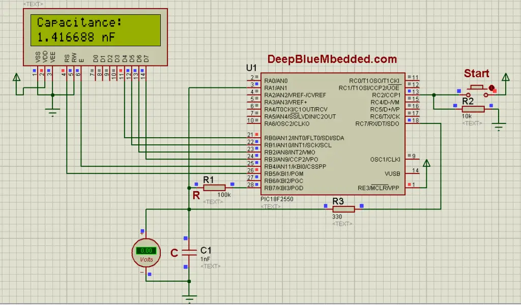
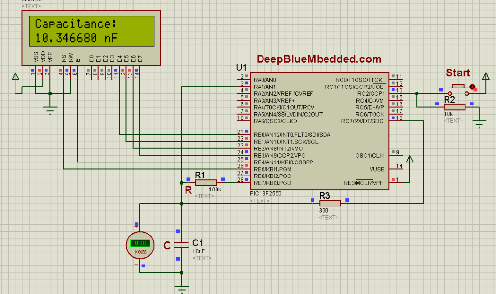
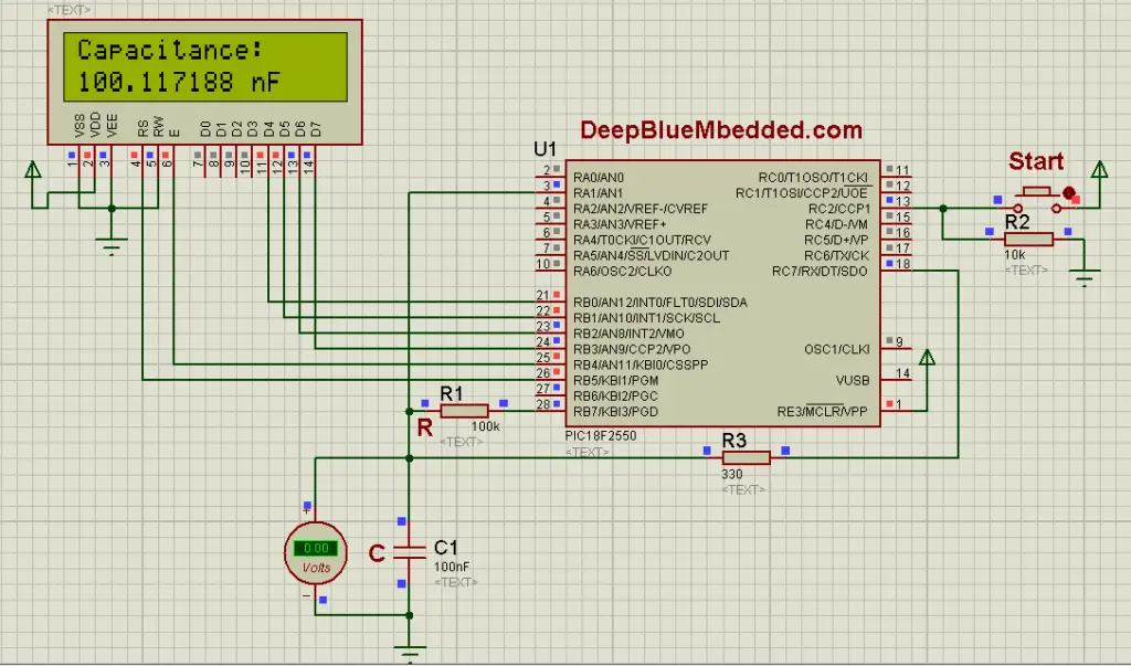
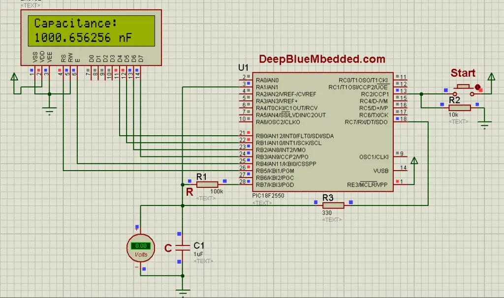
For this project, we’ll be implementing the ADC-based measurement system. With PIC18F2550 microcontroller, R=100k, and Alphanumeric 16×2 LCD module for display.
Check these tutorials as a reference
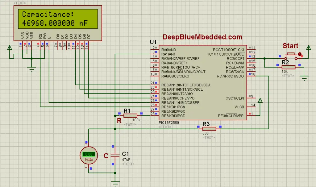
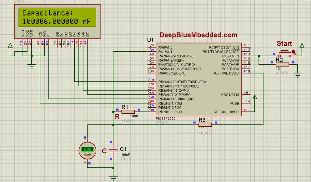
4.1 circuit diagram
4.2 code listing
|
1 2 3 4 5 6 7 8 9 10 11 12 13 14 15 16 17 18 19 20 21 22 23 24 25 26 27 28 29 30 31 32 33 34 35 36 37 38 39 40 41 42 43 44 45 46 47 48 49 50 51 52 53 54 55 56 57 58 59 60 61 62 63 64 65 66 67 68 69 70 71 72 73 74 75 76 77 78 79 80 81 82 83 84 85 |
#include <xc.h> #include "config.h" #include "LCD.h" #include <stdint.h> #include <stdio.h> #define _XTAL_FREQ 48000000 #define R 100000 #define Start_Btn_D TRISC2 #define Start_Btn RC2 #define Control_PIN_D TRISB7 #define Control_PIN RB7 #define Discharge_D TRISC7 #define Discharge RC7 //---------------------------------- //--[ Globals ]-- uint16_t TMR1_C = 0, AD_RES; uint32_t Tau; double Capacitance; char Buffer[20]; //---------------------------------- //-----[ Routines Prototypes ]------ void TMR1_Init(); void ADC_Init(); void IO_Init(); void Update_Display(); //---------------------------------- //---------[ Main Routine ]--------- void main(void) { IO_Init(); ADC_Init(); LCD_Init(); LCD_Clear(); TMR1_Init(); while(1) { if(Start_Btn) { TMR1 = 0x0000; TMR1_C = 0; Control_PIN = 1; // Charge Through R Discharge_D = 1; // The Small Resistor is disconnected (High-Impedance or Z) // Setting The Pin To Input Makes It High-Impedance (disconnected) TMR1ON = 1; // Start TMR1 GO_nDONE = 1; // Start ADC __delay_ms(250); } // Update The LCD Display Update_Display(); __delay_ms(100); } return; } //---------------------------------- //-------------[ ISR ]-------------- void __interrupt() ISR(void) { if(TMR1IF) { TMR1_C++; TMR1IF = 0; } if(ADIF) { AD_RES = (ADRESH<<2)+(ADRESL>>6); // Save result if(AD_RES >= 647) { TMR1ON = 0; Tau = TMR1+65536*TMR1_C; // Tau is TMR1 Ticks (Not in seconds) // Covert Timer Ticks To Time. Then Divide By R To Get C Capacitance=(166.66666667*Tau)/R; // Discharge The Capacitor & Stop ADC Control_PIN = 0; Discharge_D = 0; Discharge = 0; TMR1_C = 0; } else { GO_nDONE = 1; } ADIF = 0; } } //----------[ END OF ISR ]---------- |
4.3 simulation testing
| 1nF Capacitor Test
|
| 10nF Capacitor Test
|
| 100nF Capacitor Test
|
| 1μF Capacitor Test
|
| 47uF Capacitor Test
|
| 100μF Capacitor Test
|
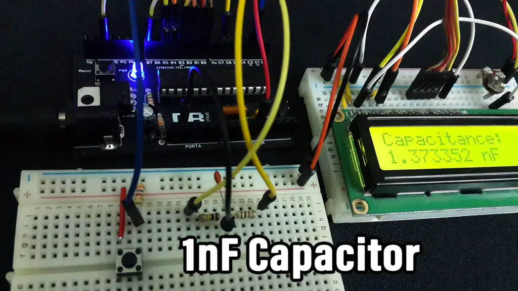
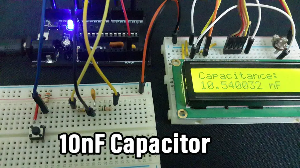
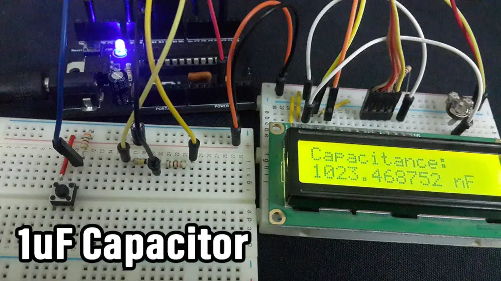
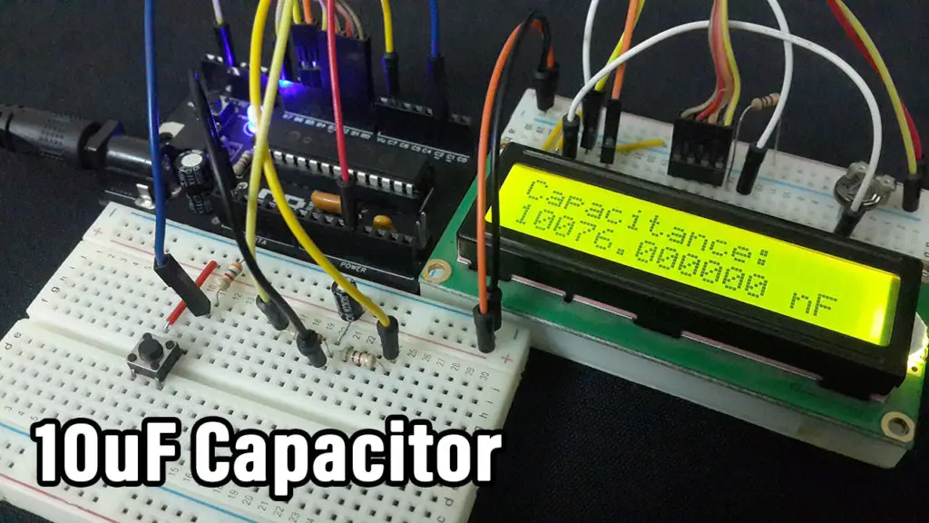
4.4 prototyping & testing
 |
 |
 |
 |
4.5 Download Project Files

thank you.. nice work ????
hi engineer khaled
think you for your efort
i want vedies of the arm micro controller
the vedios are help me for understand
thank you very much