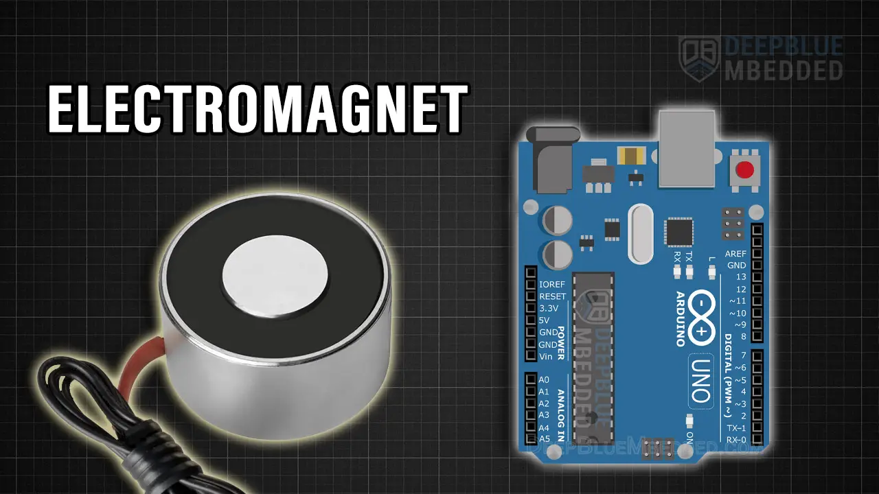
In this tutorial, you’ll learn how to do Arduino Electromagnet Control and use the Electromagnet Module with Arduino to turn it ON/OFF and control the field strength. We’ll also create an Arduino Electromagnet Example Project which can be a very good starting point for your Arduino + Electromagnet project idea. Without further ado, let’s get right into it!
Table of Contents
- Introducing Arduino Electromagnet
- Arduino Electromagnet Circuit Diagram
- Arduino Electromagnet Control Code Example
- Arduino Electromagnet Field Strength Control
- Electromagnet Field Direction
- Arduino Electromagnet Concluding Remarks
Introducing Arduino Electromagnet
An Electromagnet is constructed by winding a coil around a conductive core object and applying a voltage across the terminals of the coil. This will form a magnetic field around the structure and make it act just like a magnet that can be used for so many applications (buzzers, relays, picking up stuff, coil guns, valves, MRI machines, and much more).
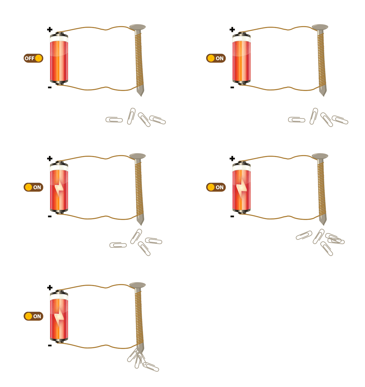
The graphic above shows you how a simple electromagnet works and the magnetism effect that results when the coil is turned ON. You can wind up a coil around a ferromagnetic core to create a DIY module but be careful with the total resistance of the coil, the current consumption, and the current rating of the coil wire itself. If you over-drive it, the coil can easily create a short circuit that will damage your output driver transistor.
In practice, we typically use an electromagnet module like the one shown below in various embedded systems projects (using Arduino, ESP32, or any other microcontroller). It’s readily available and widely used in electronics projects.
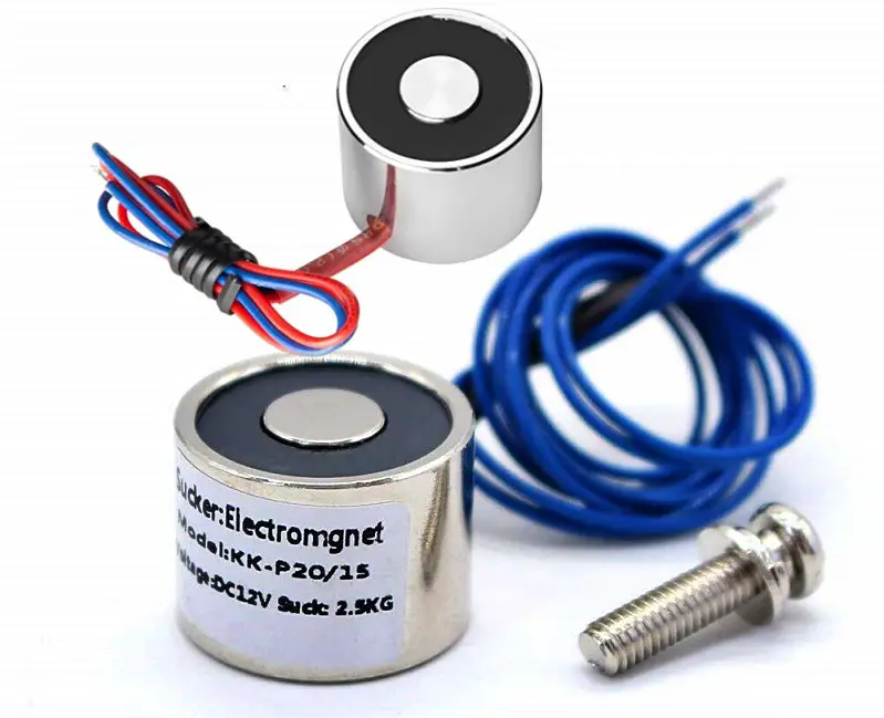
Electromagnet Technical Specs
Here are the main specs of an electromagnet that you should be looking for carefully:
- Rated Voltage: usually it’s about 12v
- Rated Current: this is the current drawn by the Electromagnet when you apply the rated voltage (e.g. my electromagnet is rated to 0.3A)
- Lifting Force: this represents the pulling force of the electromagnet when it’s activated, it can be anything from 1kg to 100kg or even more. My Electromagnet has a lifting force of 5kg.
Buy an Electromagnet Module: you can find it here on Amazon.com
Note That this Electromagnet module has a noticeable Residual Magnetism effect which makes it tricky to work with especially when you’re planning to use it to life (small light-weight objects). What you’re going to notice is that even when you turn it OFF, the small objects will still be sticking to the turned OFF Electromagnet. It’ll require a tiny external force to pull them apart, unless the object is relatively heavy, only then gravity will do the job.
Arduino Electromagnet Circuit Diagram
Here is the wiring diagram for the Arduino Electromagnet control circuit using a TIP120 BJT transistor as a driver switch. Note that the Electromagnet is being driven by the TIP120 transistor which is taking a 12v DC from an external power supply. Also, note that the ground of the external power supply is also connected to the ground of the Arduino board.
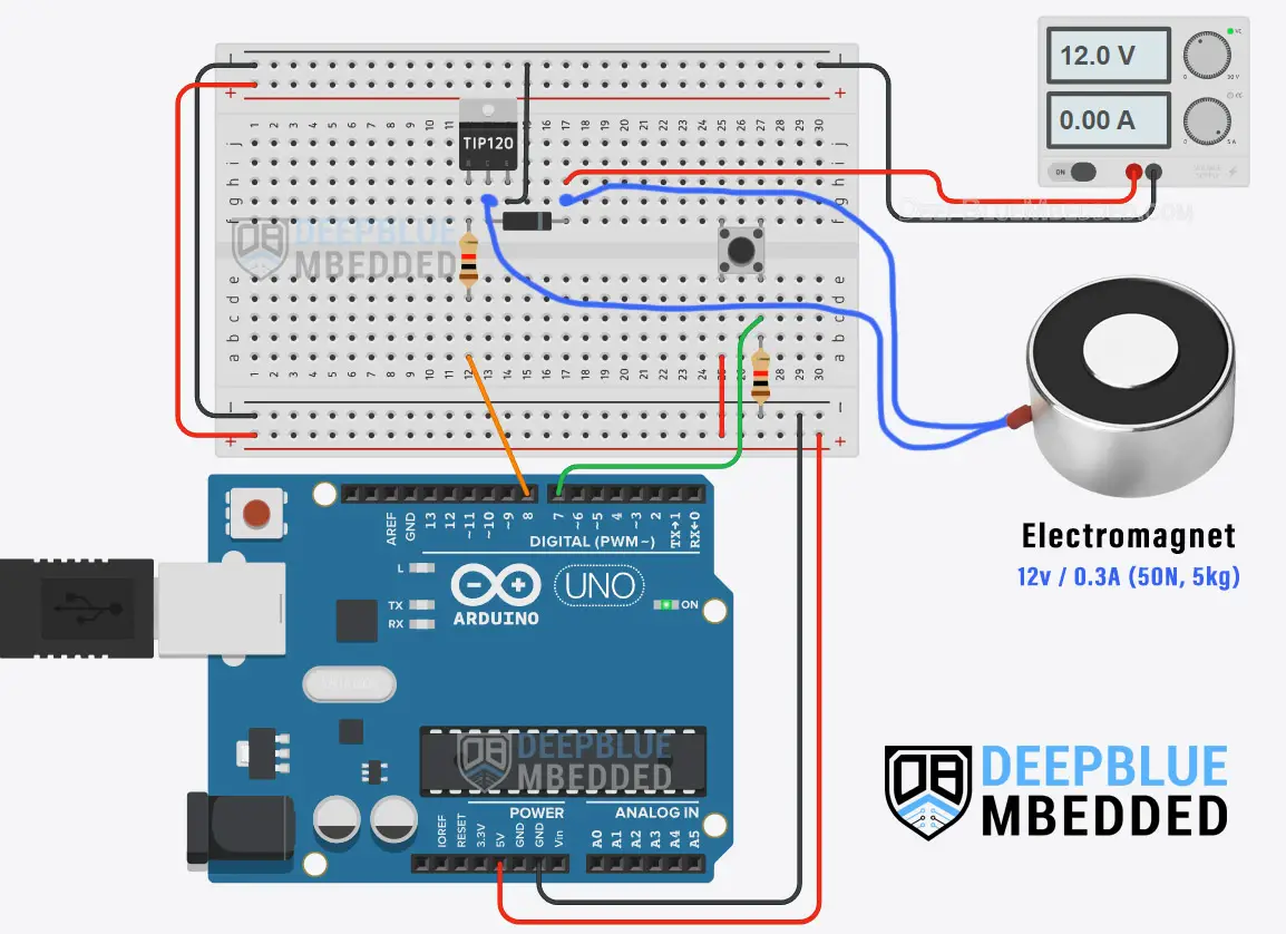
Note That a FlyBack Diode (also known as FlyWheel diode) is placed parallel to the electromagnet to protect the output driver transistor (TIP120) from the inductive spikes that result from switching the electromagnet’s coil ON and OFF.
It’s highly recommended to check out this Arduino + Transistor Tutorial to learn more about how to use BJT transistors with Arduino in your projects, how to calculate the base resistor’s value, and much more.
This article will give more in-depth information about BJT transistors and how to use NPN/PNP transistors with Arduino to control various devices.
Arduino Electromagnet Control Code Example
In this example project, we’ll use an Arduino + Electromagnet with a TIP120 output driver transistor. A push button will be used to turn the Electromagnet ON and OFF each time the button is clicked.
The input button debouncing technique that we’ll be using in this project is demonstrated in the tutorial linked below as well as many other button debouncing techniques. It’s a great tutorial that is worth checking out if you’d like to go deeper into this subject.
This article will provide you with more in-depth information about Arduino button debouncing techniques both hardware & software methods. With a lot of code examples & circuit diagrams.
The core logic of this application which take input button pin reading, debouncing, and applying control signals to the TIP120 output driver transistor that turns ON and OFF the Electromagnet module.
We’ll use the built-in timer-based millis() function to achieve this timing behavior without inserting any sort of delay into the code. If you’d like to learn more about this, it’s highly recommended to check out this tutorial.
Wiring
The wiring diagram for this example project is shown in the previous section, scroll up and check it out. Below is an image of how the whole setup looks like at the end, ready for the test.
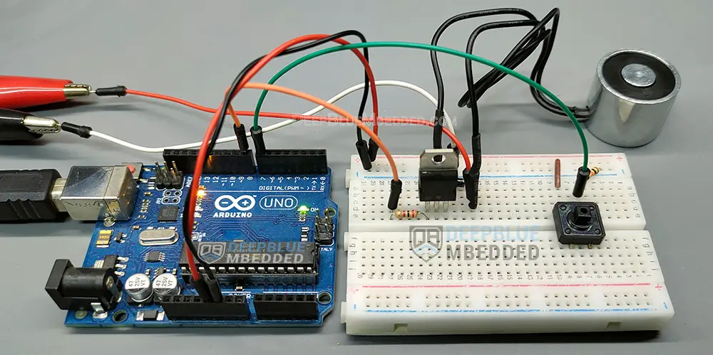
Code Example
Here is the full code listing for this example.
|
1 2 3 4 5 6 7 8 9 10 11 12 13 14 15 16 17 18 19 20 21 22 23 24 25 26 27 28 29 30 31 32 33 34 |
/* * LAB Name: Arduino Electromagnet Control * Author: Khaled Magdy * For More Info Visit: www.DeepBlueMbedded.com */ #define BTN_PIN 7 #define EM_PIN 8 unsigned long T1 = 0, T2 = 0; uint8_t TimeInterval = 5; // 5ms void setup() { pinMode(BTN_PIN, INPUT); pinMode(EM_PIN, OUTPUT); } void loop() { T2 = millis(); if( (T2-T1) >= TimeInterval) // Every 5ms { // Read The Electromagnet Enable Button State if (debounce()) { digitalWrite(EM_PIN, !digitalRead(EM_PIN)); // Toggle (Enable/Disable) } T1 = millis(); } } bool debounce(void) { static uint16_t btnState = 0; btnState = (btnState<<1) | (!digitalRead(BTN_PIN)); return (btnState == 0xFFF0); } |
Code Explanation
First of all, we define the 2 IO pins used for the Arduino-Electromagnet BJT Transistor driver & the push button input reading.
|
1 2 |
#define BTN_PIN 7 #define EM_PIN 8 |
And we’ll also define a couple of variables that we’ll use to store timestamps to execute the application’s core logic at a fixed time interval ( TimeInterval = 5ms ). The way it works is extensively demonstrated in this tutorial.
|
1 2 |
unsigned long T1 = 0, T2 = 0; uint8_t TimeInterval = 5; // 5ms |
setup()
in the setup() function, we’ll set the pinMode for the IO pins and initialize the motor speed control output pins to be LOW, by writing 0 to the analogWrite() function.
|
1 2 |
pinMode(BTN_PIN, INPUT); pinMode(EM_PIN, OUTPUT); |
loop()
in the loop() function, we’ll check the timer-based millis function to execute the core logic every 5ms. Every 5ms, we’ll read the push button input pin & debounce it. If the button is clicked by the user, we’ll toggle the output enable of the Electromagnet’s driver (TIP120 BJT Transistor).
|
1 2 3 4 5 6 7 8 9 10 11 |
void loop() { T2 = millis(); if( (T2-T1) >= TimeInterval) // Every 5ms { // Read The Electromagnet Enable Button State if (debounce()) { digitalWrite(EM_PIN, !digitalRead(EM_PIN)); // Toggle (Enable/Disable) } T1 = millis(); } } |
debounce()
This function is used to debounce the push button input pin and it’s explained in great detail in this tutorial.
|
1 2 3 4 5 6 |
bool debounce(void) { static uint16_t btnState = 0; btnState = (btnState<<1) | (!digitalRead(BTN_PIN)); return (btnState == 0xFFF0); } |
Testing Results
Arduino Electromagnet Field Strength Control
Can I Control The Field Strength of an Electromagnet With PWM?
The answer is YES, applying a variable duty cycle PWM signal to the driver of an electromagnet will result in a variable lifting strength for your Electromagnet module. However, you need to keep in mind that the default PWM frequency of the Arduino is 490Hz or 980Hz. Which is obviously within the audible range of human beings.
The low-frequency PWM output of Arduino will make your Electromagnet generate a whining noise that can be annoying to hear. This is a very common issue in electronics generally and that’s why most drivers (LEDs, Motors, etc) are designed to have a PWM switching frequency at 20kHz. We just can’t hear it anyway so it has become a common practice.
This tutorial will give you more information about the Arduino TimerOne Library, and more specifically How To Set Up a PWM Output With a 20kHz Switching Frequency if you want to try it out.
This article will provide you with more in-depth information about Arduino TimerOne Library and how to use it to set up timer interrupts or PWM output with custom frequencies (e.g. 20kHz).
Electromagnet Field Direction
One question that may come to your mind is: what would happen if I reversed the current flow direction? Would it flip the direction of lifting?
The answer is nothing would change. The Electromagnet will still lift objects the way it did when the current was flowing in the other direction. The lifting force will always be towards that “black ring face” no matter what direction the current is flowing in.
You can try & verify this on your own by swapping the Electromagnet pins in the circuit.
Required Parts List
Here is the full components list for all the parts that you’d need to perform the practical LABs mentioned here in this article and for the whole Arduino Programming series of tutorials found here on DeepBlueMbedded. Please, note that those are affiliate links and we’ll receive a small commission on your purchase at no additional cost to you, and it’d definitely support our work.
Download Attachments
You can download all attachment files for this Article/Tutorial (project files, schematics, code, etc..) using the link below. Please consider supporting my work through the various support options listed in the link down below. Every small donation helps to keep this website up and running and ultimately supports our community.
Arduino Electromagnet Concluding Remarks
To conclude this tutorial, we can say that you can easily control an Electromagnet with Arduino and an output driver transistor. The Electromagnet’s lifting force can be controlled in a variable way using a PWM signal, preferably 20kHz. To learn more about Arduino PWM, it’s highly recommended that you check out this Arduino PWM Tutorial.
If you’re just getting started with Arduino, you need to check out the Arduino Getting Started [Ultimate Guide] here.
And follow this Arduino Series of Tutorials to learn more about Arduino Programming.

![Arduino TimerOne Library Code Examples [Tutorial] Arduino TimerOne Library Code Examples [Tutorial]](https://deepbluembedded.com/wp-content/uploads/2023/05/Arduino-TimerOne-Library-Code-Examples-Tutorial-300x169.jpg)
