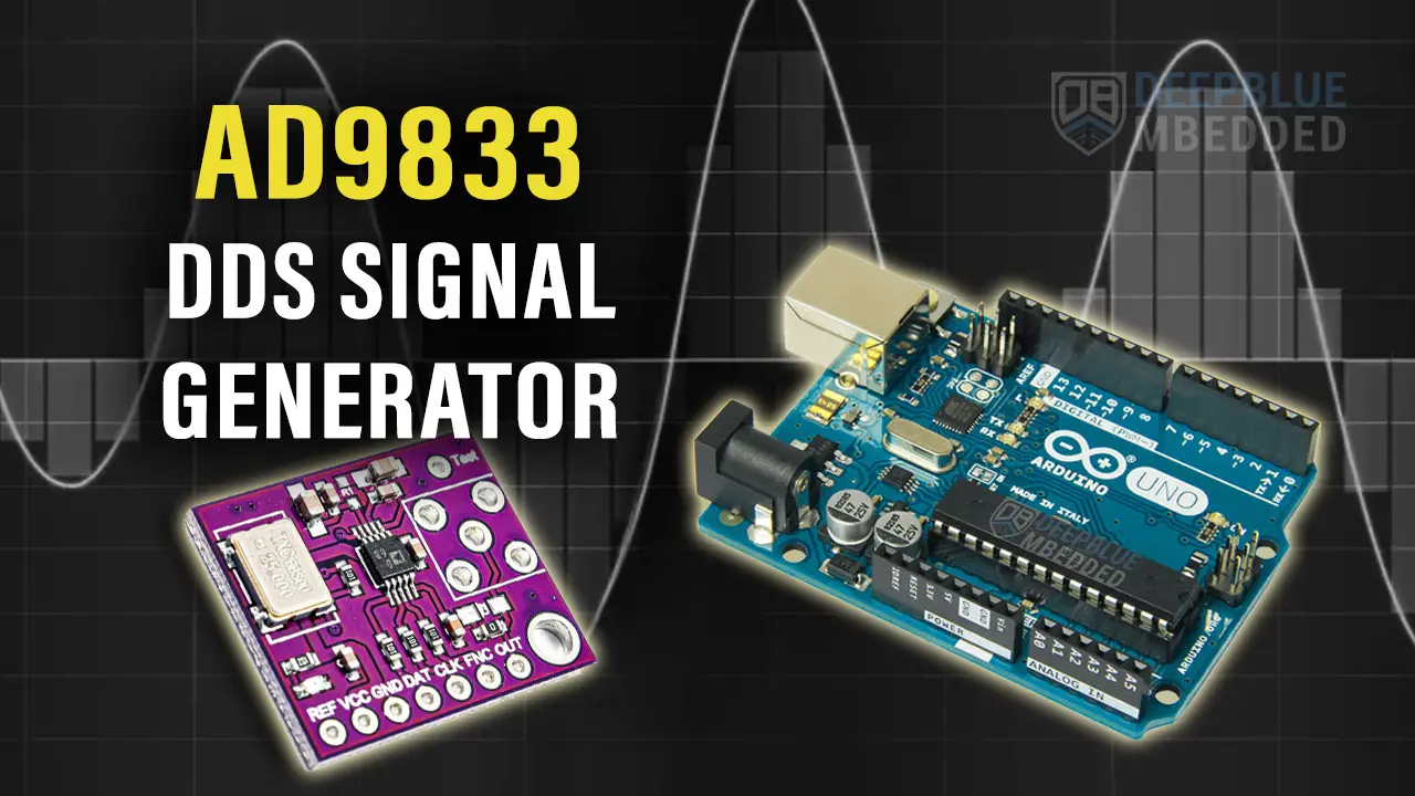
This is a comprehensive guide for Arduino AD9833 Signal Generator Module Interfacing. You’ll learn how to use AD9833 With Arduino To Create a Function Generator Project to practice what we’ll be learning in this tutorial.
We’ll start by explaining how the AD9833 DDS Signal Generator module works, its pinout, and how to connect it With Arduino. Then, we’ll install the Arduino AD9833 Library, and create an Arduino Signal Generator project with the AD9833 Function Generator module. Without further ado, let’s get right into it!
Table of Contents
- Arduino AD9833
- Arduino AD9833 Interfacing
- Arduino AD9833 Library Installation
- Arduino AD9833 Signal Generator Example
- Arduino AD9833 DDS Function Generator Projects’ Tips
- Wrap Up
Arduino AD9833
The AD9833 is a low-power, programmable waveform generator capable of producing sine, triangular, and square wave outputs. The output frequency and phase are software-programmable which makes it easily tunable. The frequency registers are 28 bits wide: with a 25 MHz clock rate, a resolution of 0.1 Hz can be achieved; with a 1 MHz clock rate, the AD9833 can be tuned to 0.004 Hz resolution.
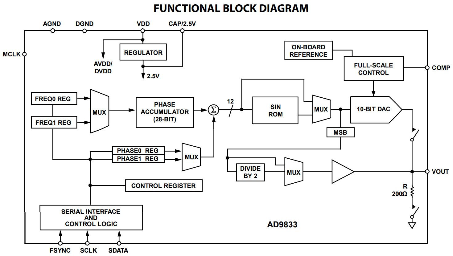
The functional block diagram shown above may not make too much sense to many readers unless you’re already familiar with DDS (Direct Digital Synthesis) for waveform generation. It’s a topic for a future tutorial where I’ll show you how we can replicate what you’re seeing in this hardware block diagram in software and run it on a small microcontroller to generate waveform using the DDS technique.
For this tutorial, we’ll use the AD9833 module with Arduino to generate waveforms and control the output waveform shape and frequency over the SPI bus communication with the AD9833 chip.
AD9833 Tech Specs
| Operating Voltage | 2.3v To 5.5v |
| Interface | Serial Peripheral Interface (SPI) |
| Frequency Resolution | 28 Bit |
| Output Waveforms | Sine, Triangular (Sawtooth), Square |
| Output Waveforms’ Frequency | Sine: 0 To 12.5MHz Square: 0 To 1MHz Triangular: 0 To 1MHz |
| Output Waveform Voltage | Typically 0.6Vpp to 0.9Vpp (sine wave), 5Vpp (square wave); adjustable via external components such as opAmps, etc |
AD9833 Applications
Waveform generation is required in various types of sensing, actuation, and time domain reflectometry (TDR) applications. Here are some applications where you might consider using a DDS waveform generator like the AD9833:
- Sweep/clock generators
- Frequency stimulus/waveform generation
- Liquid and gas flow measurement
- Line loss/attenuation
- Test and medical equipment
- Sensors like: proximity, motion, and defect detection
Buy an AD9833 Module: you can find it here on Amazon.com
You can find more information about the AD9833 DDS Signal Generator IC in its Datasheet from Analog Device.
Arduino AD9833 Interfacing
Now, let’s move to interfacing the AD9833 DDS Signal Generator with Arduino. Let’s check the pinout, pin functions, and the wiring diagram.
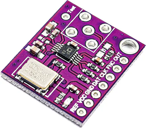
AD9833 Pinout
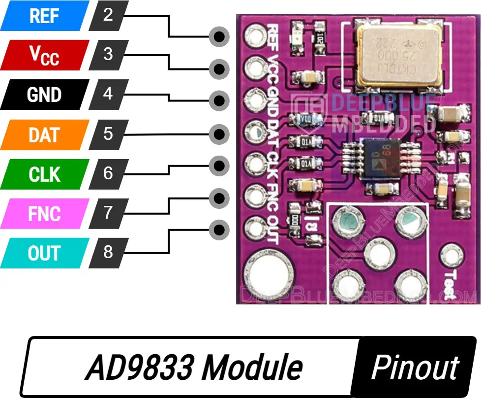
REF is the reference voltage pin.
VCC is the module’s power supply input pin (connects to +5v).
GND is the ground pin.
DAT is the SPI DATA input pin, hook it to the microcontroller’s (MOSI) pin.
CLK is SPI CLOCK pin, hook it to the microcontroller’s SPI SCK pin.
FNC is the SPI Slave Select (Slave Enable) pin, usually referred to as SS pin. It can be connected to any GPIO pin on your microcontroller.
OUT is the output waveform signal’s pin.
Wiring AD9833 With Arduino
Here is the wiring diagram for the AD9833 DDS Signal Generator with Arduino that we’ll be using in the example project hereafter in this tutorial.
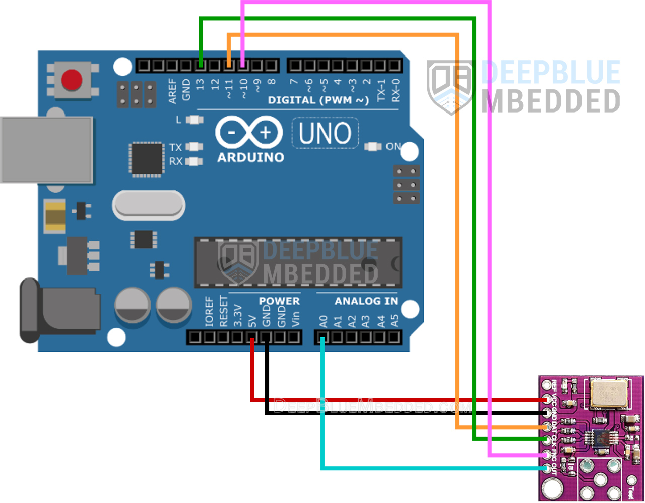
| Arduino | AD9833 | |
| +5V |
| Vcc |
| GND |
| GND |
| 10 |
| FNC |
| 11 |
| DATA |
| 13 |
| CLK |
| A0 |
| OUT |
| No Connection | REF |
Arduino AD9833 Library Installation
You can download and install the Arduino AD9833 library manually from GitHub, or alternatively, install it within the Arduino IDE itself. Just open the library manager. Tools > Manage Libraries > Search for AD9833. Then, click Install and let it finish the installation.
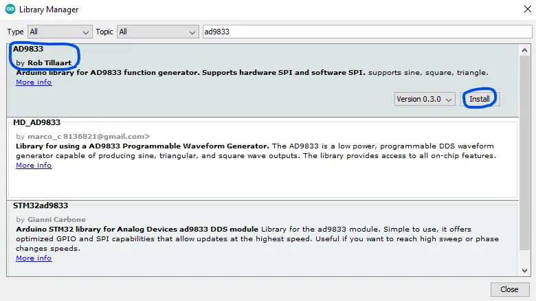
Now, you can easily use the Arduino AD9833 library and check the built-in examples for the library to help you get started.
We’ll move now to the practical code example to test the Arduino AD9833 DDS Signal Generator Module interfacing.
Arduino AD9833 Signal Generator Example
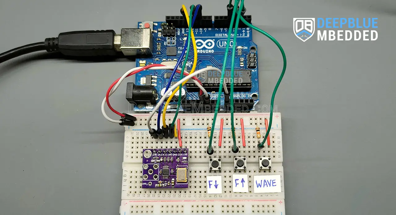
Now, we’re ready to create our first Arduino Signal Generator project with the AD9833 DDS Function Generator Module. In this example project, we’ll use the AD9833 to generate variable-frequency variable-waveform output signals. Using 3x push buttons, we’ll control (Wave Shape, Frequency Increase, Frequency Decrease).
To visualize the waveform output signal, we’ll feed it back to our Arduino’s A0 analog input channel and send the readings over the serial port to the PC where we’ll view the signal on the serial plotter.
Wiring
The wiring diagram for this example project is shown in the previous section, scroll up and check it out. Below is an image of how the whole setup looks like at the end, ready for the test.
Example Code
Here is the full code listing for this example.
|
1 2 3 4 5 6 7 8 9 10 11 12 13 14 15 16 17 18 19 20 21 22 23 24 25 26 27 28 29 30 31 32 33 34 35 36 37 38 39 40 41 42 43 44 45 |
#include <AD9833.h> #include <Pushbutton.h> #define WAVE_BTN_PIN 2 #define FINC_BTN_PIN 3 #define FDEC_BTN_PIN 4 Pushbutton WaveButton(WAVE_BTN_PIN); Pushbutton FIncButton(FINC_BTN_PIN); Pushbutton FDecButton(FDEC_BTN_PIN); AD9833 AD(10); //HW SPI (FNC:pin10, DAT:pin11, CLK:pin13) int WaveTable[3] = {AD9833_SINE, AD9833_SQUARE1, AD9833_TRIANGLE}; int i = 0; // Index For The WaveTable Array int Freq = 10; // 10Hz void setup() { Serial.begin(115200); AD.begin(); AD.setFrequency(Freq, 0); // 10Hz AD.setWave(AD9833_SINE); } void loop() { if (WaveButton.getSingleDebouncedPress()){ AD.setWave(WaveTable[i++]); if(i == 3){ i = 0; } } if (FIncButton.getSingleDebouncedPress()){ Freq += 10; AD.setFrequency(Freq, 0); } if (FDecButton.getSingleDebouncedPress()){ if(Freq > 10){ Freq -= 10; } AD.setFrequency(Freq, 0); } Serial.println(analogRead(A0)); } |
Code Explanation
First of all, we need to include the Arduino AD9833.h & Pushbutton.h libraries to use the AD9833 DDS module and the button debouncing library.
|
1 2 |
#include <AD9833.h> #include <Pushbutton.h> |
Next, we’ll define the 3x IO pins that we’ll use for the input push buttons for the following controls: (Wave Shape Change, Frequency Increase, and Frequency Decrease). We’ll also create 3 objects of the Pushbutton class for our 3 buttons, and we’ll create an object of the AD9833 class for the signal generator module.
|
1 2 3 4 5 6 7 8 9 |
#define WAVE_BTN_PIN 2 #define FINC_BTN_PIN 3 #define FDEC_BTN_PIN 4 Pushbutton WaveButton(WAVE_BTN_PIN); Pushbutton FIncButton(FINC_BTN_PIN); Pushbutton FDecButton(FDEC_BTN_PIN); AD9833 AD(10); //HW SPI (FNC:pin10, DAT:pin11, CLK:pin13) |
Then, we’ll create some variables to handle the waveform shape change and store the current output signal’s frequency.
|
1 2 3 |
int WaveTable[3] = {AD9833_SINE, AD9833_SQUARE1, AD9833_TRIANGLE}; int i = 0; // Index For The WaveTable Array int Freq = 10; // 10Hz |
setup()
in the setup() function, we initialize the AD9833 module and set the default output waveform to AD9833_SINE @ 10Hz frequency. We have also to initialize the serial port to send the measured signal back to the PC for display on the serial plotter.
|
1 2 3 4 |
Serial.begin(115200); AD.begin(); AD.setFrequency(Freq, 0); // 10Hz AD.setWave(AD9833_SINE); |
loop()
In the loop() function, we’ll read the debounced state of the 3x input buttons and handle each event of them, and we finally read the analog input signal coming from the AD9833 module’s output and send it over the serial port.
The input buttons functionality is as follows:
- Frequency Inc: increases the frequency of the output waveform by 10Hz
- Frequency Dec: decreases the frequency of the output waveform by 10Hz
- Wave Change: changes the output waveform (Sine -> Square -> Triangle -> repeat..)
|
1 2 3 4 5 6 7 8 9 10 11 12 13 14 15 16 17 18 19 20 |
void loop() { if (WaveButton.getSingleDebouncedPress()){ AD.setWave(WaveTable[i++]); if(i == 3){ i = 0; } } if (FIncButton.getSingleDebouncedPress()){ Freq += 10; AD.setFrequency(Freq, 0); } if (FDecButton.getSingleDebouncedPress()){ if(Freq > 10){ Freq -= 10; } AD.setFrequency(Freq, 0); } Serial.println(analogRead(A0)); } |
Testing Result
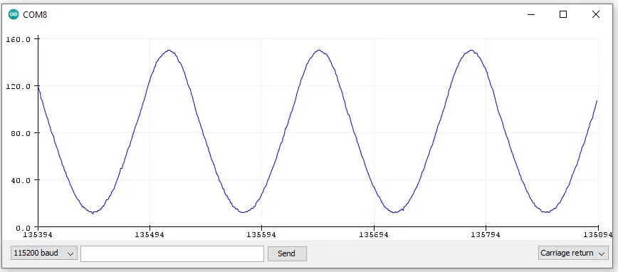
To learn more about the push button debouncing techniques and the library we’ve used in this example project, check the tutorial below.
This article will provide you with more in-depth information about Arduino button debouncing techniques both hardware & software methods. With a lot of code examples & circuit diagrams.
Arduino AD9833 DDS Function Generator Projects’ Tips
Before concluding this tutorial, let’s address some of the shortcomings of the AD9833 DDS function generator module that you’ll encounter in your project and how to go about overcoming such challenges.
AD9833 Sine & Triangular Waveforms Amplitude
The default amplitude of the output sine & triangular waveforms falls in the (0.6-0.9) Vpp, which is considered a small signal for a lot of use cases. It’s not software-controllable, though. You’ll need to add a non-inverting opAmp circuit to amplify the output waveform but make sure it doesn’t add to the THD (total harmonic distortion) of the output.
AD9833 Sine & Triangular Waveforms Offset Voltage
The output sine waveform of the AD9833 has a tiny voltage offset of around 40mv. To get rid of this you’ll need to have a rail-to-rail opAmp that will help you null the output waveform or even add some amplitude amplification, if needed.
AD9833 Square Wave Amplitude
The amplitude of the square wave output is surprisingly 5Vpp. Again, a rail-to-rail opAmp might be needed to attenuate or amplify this signal based on your project’s needs. But you need to pay attention to the opAmp’s slew rate so as not to lose a lot of the square wave harmonics.
Required Parts List
Here is the full components list for all the parts that you’d need to perform the practical LABs mentioned here in this article and for the whole Arduino Programming series of tutorials found here on DeepBlueMbedded. Please, note that those are affiliate links and we’ll receive a small commission on your purchase at no additional cost to you, and it’d definitely support our work.
Download Attachments
You can download all attachment files for this Article/Tutorial (project files, schematics, code, etc..) using the link below. Please consider supporting my work through the various support options listed in the link down below. Every small donation helps to keep this website up and running and ultimately supports our community.
Wrap Up
To conclude this tutorial, we can say that the AD9833 function generator module is a very powerful option to use with Arduino for signal generation applications. Using the Arduino AD9833 library makes it much easier to interface with the DDS function generator module and use it to generate various waveform signals with very precise controllable output frequencies.
In future tutorials, we’ll look into adding some analog circuits to amplify, attenuate, and offset the output waveform signals to make a useful Arduino Signal Generator device. We’ll also dive deeper into how DDS (direct digital synthesis) works and implement a software version of the technique on Arduino.
If you’re just starting with Arduino, check out the Arduino Getting Started [Ultimate Guide] here.
And follow this Arduino Series of Tutorials to learn more about Arduino Programming.
