In this tutorial, we’ll discuss Arduino Software Interrupts and how to generate a software interrupt (trap) in Arduino. We’ll implement an Arduino Software Interrupt Example project to test what we’ll learn throughout this tutorial. Without further ado, let’s get right into it!
Table of Contents
Software Interrupts
Software interrupts are interrupt signals that can be fired with specific software instructions. Some microcontrollers support native software interrupt instructions while others don’t have dedicated assembly instructions for the CPU to get an interrupt from the software.
Other techniques can be implemented to programmatically enforce an interrupt to the CPU within your software even if it doesn’t have a soft interrupt instruction. This of course requires some workarounds but it’s not that hard to do in general.
A software interrupt can be referred to as a Trap as well. Which is a technique to signal the CPU within the software to change the mode, throw an error, indicate an arithmetic error, or signal the OS.
Arduino Software Interrupts
It’s stated clearly in the Arduino UNO’s Atmega328p datasheet that it doesn’t have a dedicated assembly instruction to trigger a software-generated interrupt signal. But as we’ve stated earlier, we can still implement some workarounds to fire software-generated interrupt signals.
One technique to generate a software interrupt is clearly stated in the datasheet itself. Which is to enable any external interrupt pin (IRQ) and set it as an output pin. Writing to any pin of these will trigger an interrupt, and that’s how we get a software-generated interrupt even if it’s not supported by the microcontroller.
Arduino’s Atemga328p microcontroller doesn’t have a dedicated assembly instruction that generates a software interrupt. Instead, a hardware interrupt like external IRQ pins (e.g. INT0) can be written to by software to trigger an interrupt, which is also considered as a software-generated interrupt.
Arduino Software Interrupt Example
In this example project, we’ll test Arduino Software Interrupts. And here is how we’re going to do it.
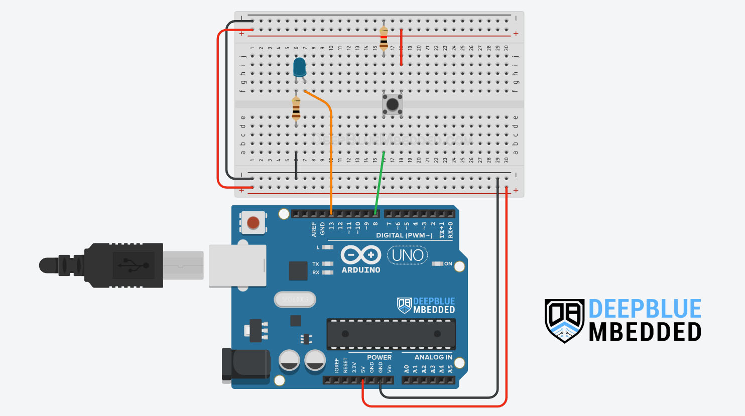
First of all, we’ll use the INT0 (IO pin2) as an interrupt signal source but will trigger it from the software and will set it as an output pin. It’s not going to be connected to the push button or anything.
The push button input, however, is going to be connected to an IO pin8 that we’ll set as an input pin. Whenever the push button is pressed we’ll debounce it, once a click is confirmed, we’ll send a pulse (LOW->HIGH, RISING) to the output pin (INT0) which is going to trigger an interrupt event.
In the ISR handler for INT0 interrupt, we’ll toggle an output LED. I know, it’s not very intuitive but it’s still a valid test to verify the concept and make sure everything behaves as expected.
Wiring
Here is the wiring diagram for this example showing how to connect the LED output, and the push button to the input pin (pin8). And note that the INT0 (pin2) is set as an output pin and left unconnected.
Arduino Software Interrupt Example Code
Here is the full code listing for this Arduino Software Interrupt Example.
|
1 2 3 4 5 6 7 8 9 10 11 12 13 14 15 16 17 18 19 20 21 22 23 24 25 26 27 28 29 30 31 32 33 34 35 36 37 38 39 40 41 42 43 44 45 |
/* * LAB Name: Arduino Software Interrupt Example * Author: Khaled Magdy * For More Info Visit: www.DeepBlueMbedded.com */ #define LED_PIN 13 #define BTN_PIN 8 #define INT0_PIN 2 unsigned long T1 = 0, T2 = 0; uint8_t TimeInterval = 5; void INT0_ISR(void) { digitalWrite(LED_PIN, !digitalRead(LED_PIN)); } void setup() { pinMode(LED_PIN, OUTPUT); pinMode(BTN_PIN, INPUT); pinMode(INT0_PIN, OUTPUT); attachInterrupt(digitalPinToInterrupt(INT0_PIN), INT0_ISR, RISING); } void loop() { T2 = millis(); if( (T2-T1) >= 5 ) { if (debounce()) { digitalWrite(INT0_PIN, LOW); delay(1); digitalWrite(INT0_PIN, HIGH); } T1 = millis(); } } bool debounce(void) { static uint16_t btnState = 0; btnState = (btnState<<1) | (!digitalRead(BTN_PIN)); return (btnState == 0xFFF0); } |
Code Explanation
We first need to define the IO pins to be used for the LED output & push button input (pin8). The (INT0 external interrupt pin = IO pin2) will be used in output mode to generate the software interrupt.
|
1 2 3 |
#define LED_PIN 13 #define BTN_PIN 8 #define INT0_PIN 2 |
INT0_ISR()
This is the ISR handler function for the INT0 external interrupt in which we’ll only do a LED toggle action. For each RISING edge on the external interrupt pin, the CPU will execute this ISR function which will toggle the output LED.
The RISING edge on the INT0 pin will come from software in the loop() function, therefore the INT0_ISR handler function is the software interrupt handler.
|
1 2 3 4 |
void INT0_ISR(void) { digitalWrite(LED_PIN, !digitalRead(LED_PIN)); } |
setup()
in the setup() function, we’ll initialize the IO pins to be used as input & output using the pinMode() function to set their modes.
|
1 2 3 |
pinMode(LED_PIN, OUTPUT); pinMode(BTN_PIN, INPUT); pinMode(INT0_PIN, OUTPUT); |
Then we’ll enable the external interrupt for the INT0 (pin2) using the attachInterrupt() function & set it to trigger on RISING edge events only.
|
1 |
attachInterrupt(digitalPinToInterrupt(BTN_PIN), INT0_ISR, RISING); |
loop()
in the loop() function, we’ll read the push button on the input pin8 and debounce it. Once a click is confirmed, we’ll send a LOW->HIGH pulse on the output INT0 pin to trigger an interrupt event from the software at the same moment when a button click is confirmed.
|
1 2 3 4 5 6 7 8 9 10 |
T2 = millis(); if( (T2-T1) >= 5 ) { if (debounce()) { digitalWrite(INT0_PIN, LOW); delay(1); digitalWrite(INT0_PIN, HIGH); } T1 = millis(); } |
If you want to learn more about the Arduino button debouncing technique used in this example, and all other possible hardware & software button debouncing techniques, check out the tutorial below which presents everything you need to know about button debouncing in one place.
This article will provide you with more in-depth information about Arduino button debouncing techniques both hardware & software methods. With a lot of code examples & circuit diagrams.
Parts List
Here is the full components list for all parts that you’d need in order to perform the practical LABs mentioned here in this article and for the whole Arduino Programming series of tutorials found here on DeepBlueMbedded. Please, note that those are affiliate links and we’ll receive a small commission on your purchase at no additional cost to you, and it’d definitely support our work.
Download Attachments
You can download all attachment files for this Article/Tutorial (project files, schematics, code, etc..) using the link below. Please consider supporting my work through the various support options listed in the link down below. Every small donation helps to keep this website up and running and ultimately supports our community.
Wrap Up
To conclude this short tutorial, we’ll highlight the fact that Arduino Software Interrupts can be generated using other hardware interrupt sources like (external IRQ pins INTx or PCINTx). Because there are no special software interrupt instructions in the Arduino’s Atmega328p microcontroller’s instruction set. But all in all, it’s still doable and the example provided in this tutorial is basically how you can also do it.
If you’re just getting started with Arduino, you need to check out the Arduino Getting Started [Ultimate Guide] here.
And follow this Arduino Series of Tutorials to learn more about Arduino Programming.
This is the ultimate guide for getting started with Arduino for beginners. It’ll help you learn the Arduino fundamentals for Hardware & Software and understand the basics required to accelerate your learning journey with Arduino Programming.
This is the complete Arduino Interrupts Tutorial. It’ll provide you with more in-depth information about interrupts in general and specifically in Arduino, how it works, how to write efficient ISR handlers, and other tips & tricks.
FAQ & Answers
A software interrupt in Arduino is an interrupt signal that’s generated by software, not hardware peripherals. It’s stated in the Arduino UNO (Atmega328p) microcontroller’s datasheet that it doesn’t support special software instructions for software interrupt generation. However, it also states that we can still generate software interrupts in Arduino using (INTx or PCINTx) pins in output mode. Writing to those pins will trigger an interrupt from the software, which is one way to do it.
There are no native software interrupts in Arduino UNO (Atmega328p) microcontroller. However, the IRQ pins (INTx and PCINT) pins can be used in output mode. Writing to those pins from the software will still trigger interrupt signals, which is also considered as software interrupts.
Hardware interrupts are generated by hardware peripherals in the microcontroller itself (like Timers, External IRQ pins, UART, SPI, etc.). Hardware modules fire various interrupt signals so the CPU gets notified about it and handles them as quickly as possible.
Software interrupts are interrupt signals that can be fired with specific software instructions. Some microcontrollers support native software interrupt instructions while others don’t have dedicated assembly instructions for the CPU to get an interrupt from the software.
