This is a comprehensive guide for Arduino CD74HC4067 Analog Multiplexer Interfacing. You’ll learn how to use CD74HC4067 With Arduino and create some example projects to practice what we’ll be learning in this tutorial. We’ll start by explaining how the Analog Switch CD74HC4067 module works, its pinout, and how to connect it With Arduino.
We’ll use the CD74HC4067 to simultaneously read 4 different analog inputs using only 1 analog input pin of the Arduino board. Using analog multiplexers like the CD74HC4067 can dramatically extend (increase) the ADC analog input pins of your Arduino board. Without further ado, let’s get right into it!
Table of Contents
- Arduino CD74HC4067 Analog Multiplexer
- Arduino CD74HC4067 Interfacing
- Arduino CD74HC4067 Library Installation
- Arduino CD74HC4067 Analog Multiplexer Example
- Arduino CD74HC4067 Switching Speed
- Wrap Up
Arduino CD74HC4067 Analog Multiplexer
An Analog Multiplexer (Switch) is a device that operates exactly like a digital multiplexer in terms of the core functionality of routing a signal to multiple outputs. However, an Analog Multiplexer does this for analog signals (not digital) exactly like the built-in analog switch inside an ADC in any microcontroller. It helps us switch between multiple input pins to share the same resource (ADC).

This can be helpful in case you’d like to extend the number of analog input pins to your microcontroller’s ADC or any other application where you need to programmatically route an analog signal to go into different paths. Another example is to use it with an OpAmp to switch between feedback resistors to have a programmable gain amplifier circuit. And so many more other applications.
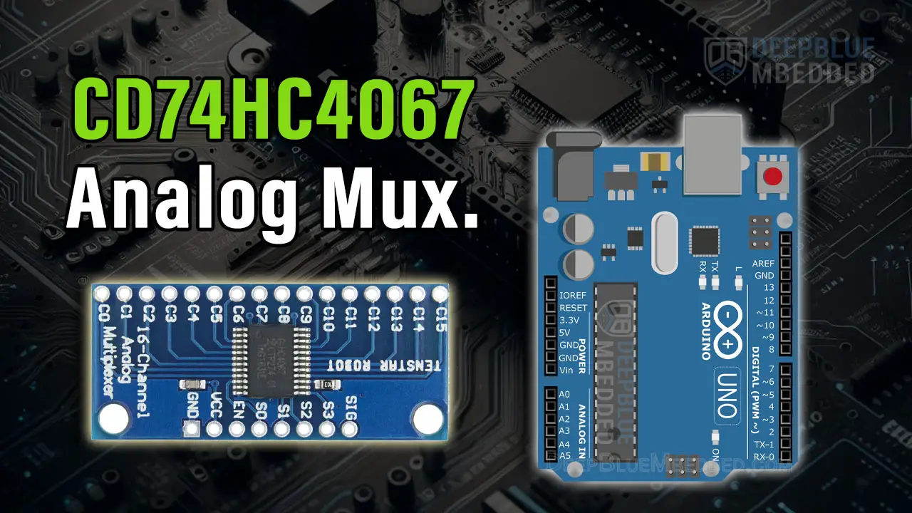
The CD74HC4067 is an analog multiplexer IC that has 16 channels that can be routed to a single pin in/out. It works in both directions so you can refer to it as a multiplexer or demultiplexer. Below is an image for the CD74HC4067 breakout module that we’ll be using in this tutorial.

Buy a CD74HC4067 Analog Mux: you can find it here on Amazon.com
You can find more information about the CD74HC4067 analog multiplexer IC in its Datasheet from Ti.
Arduino CD74HC4067 Interfacing
Now, let’s move to interfacing the CD74HC4067 Analog Multiplexer with Arduino. Let’s check the pinout, pin functions, and the wiring diagram.
CD74HC4067 Pinout

AN CHx are the 16 channels of the analog multiplexer. The common signal (Sig) pin gets routed to any of those 16 channels depending on the address (S0-S3) pins’ states.
VCC is the module’s power supply input pin (connects to +5v).
GND is the ground pin.
EN is the Enable pin which is an Active-LOW pin. Setting the EN pin to HIGH, disables the multiplexer output; no channel is routed to the Sig pin, the address state has no effect in this case. Clearing the EN pin to LOW, makes the multiplexer active; the selected channel by the S0-S3 address control pins is therefore routed to the common in/out Signal (Sig) pin.
S0-S3 are the address (selector) control pins that determines which analog channel gets routed to the common (sig) pin.
Sig is the common signal pin.
Wiring CD74HC4067 With Arduino
Here is the wiring diagram for the CD74HC4067 Analog Multiplexer with Arduino that we’ll be using in the example project hereafter in this tutorial.

Arduino CD74HC4067 Library Installation
You can download and install the Arduino CD74HC4067 library manually from GitHub, or alternatively, install it within the Arduino IDE itself. Just open the library manager. Tools > Manage Libraries > Search for CD74HC4067. Then, click Install and let it finish the installation.

Now, you can easily use the Arduino CD74HC4067 library and check the built-in examples for the library to help you get started.
We’ll move now to the practical code example to test the Arduino CD74HC4067 Analog Multiplexer interfacing.
Arduino CD74HC4067 Analog Multiplexer Example
Now, we’re ready to create our first Arduino project with the CD74HC4067 Analog Multiplexer. In this example project, we’ll use the CD74HC4067 to extend 1 analog input pin of the Arduino (A0) and make it accept up to 16 different analog inputs. For the sake of circuit simplicity, I’ll only use 4 analog channels of the CD74HC4067 module. You’ll get the idea anyway and it’s up to you to choose the number of extra analog input channels that are required in your project.
To visualize the analog input reading, we’ll scale down the 10-bit ADC readings to be 8-bit and write it as a duty cycle to 4 different PWM output pins to which we’ll hook up 4 LEDs to control the brightness of the LEDs using 4x Potentiometers and only 1 ADC pin of the Arduino (A0).
Wiring
The wiring diagram for this example project is shown in the previous section, scroll up and check it out. Below is an image of how the whole setup looks like at the end, ready for the test.

Example Code
Here is the full code listing for this example.
/*
 * LAB Name: Arduino CD74HC4067 Analog Multiplexer Example
 * Author: Khaled Magdy
 * For More Info Visit: www.DeepBlueMbedded.com
*/
#include <CD74HC4067.h>

#define SIG_PIN A0
#define LED0_PIN 6
#define LED1_PIN 9
#define LED2_PIN 10
#define LED3_PIN 11

CD74HC4067 my_mux(5, 4, 3, 2);  // (S0, S1, S2, S3)
int LED_PINS[4] = {LED0_PIN, LED1_PIN, LED2_PIN, LED3_PIN};

void setup()
{
  pinMode(LED0_PIN, OUTPUT);
  pinMode(LED1_PIN, OUTPUT);
  pinMode(LED2_PIN, OUTPUT);
  pinMode(LED3_PIN, OUTPUT);
  Serial.begin(9600);
}

void loop()
{
  for(int i=0; i<4; i++)
  {
    my_mux.channel(i);
    analogWrite(LED_PINS[i], analogRead(SIG_PIN)>>2);
    Serial.print(analogRead(SIG_PIN));
    Serial.print(", ");
  }
  Serial.println("");
}
Code Explanation
First of all, we need to include the Arduino CD74HC4067.h library to use the analog multiplexer module.
#include <CD74HC4067.h>
Next, we’ll define the IO pins that we’ll use for the analog input pin and the 4x address (selector) control pins.
#define SIG_PIN A0
#define LED0_PIN 6
#define LED1_PIN 9
#define LED2_PIN 10
#define LED3_PIN 11

int LED_PINS[4] = {LED0_PIN, LED1_PIN, LED2_PIN, LED3_PIN};
Then, we’ll create an object of the CD74HC4067 class and assign the selector control pins to it.
CD74HC4067 my_mux(5, 4, 3, 2); // (S0, S1, S2, S3)
setup()
in the setup() function, we initialize the IO pins to be used for LED outputs and we also start a serial port communication to send the analog readings of the 4 channels to the serial monitor.
pinMode(LED0_PIN, OUTPUT);
pinMode(LED1_PIN, OUTPUT);
pinMode(LED2_PIN, OUTPUT);
pinMode(LED3_PIN, OUTPUT);
Serial.begin(9600);
loop()
In the loop() function, we’ll create a 4-times loop to take the readings of each channel of the 4 used channels (CH0 – CH3), scale the reading down to 8bit, write the scaled reading to the PWM output pins (LED brightness), and finally print the raw ADC reading of each channel to the serial monitor.
void loop()
{
  for(int i=0; i<4; i++)
  {
    my_mux.channel(i);
    analogWrite(LED_PINS[i], analogRead(SIG_PIN)>>2);
    Serial.print(analogRead(SIG_PIN));
    Serial.print(", ");
  }
  Serial.println("");
}
Simulation
Here is the simulation result for this project on the Wokwi simulator.
You can check this simulation project on Wokwi using this link.
I’ve inserted a small delay(10) between each switching action of the CD74HC4067 analog multiplexer just to prevent cross-coupling between the channels and make the application run flawlessly on the simulator environment. However, on a real Arduino-CH74HC4067 hardware setup, there is no need to have any delay at all. We’ll measure the maximum switching speed of the CD74HC4067 later in this tutorial.
Testing Results
Here is the result of testing this project code example on my Arduino UNO board.
By using the CD74HC4067, we could easily add up to 16 additional analog inputs to our Arduino board while using only one analog input pin (A0). However, this process did cost us 4 digital output pins to control the selector (address) pins of the CD74HC4067 module.
Combining the CD74HC4067 with a shift register like 74HC595 can push this setup way further and you’ll end up having more analog inputs than you might ever need in any project. You’ll only be limited by the switching speed which is what we’re going to address in the next section hereafter.
Arduino CD74HC4067 Switching Speed
Before concluding this tutorial, let’s address the switching speed of the CD74HC4067 analog multiplexer IC. To properly measure the switching speed of the analog multiplexer IC, let’s first define it. To define the switching speed of an analog multiplexor, let’s consider the following example:
Assume we’ve hooked up two constant analog inputs to the CD74HC4067, one of them is 2.5v and the other is 5v. We’ll observe the output on the Sig pin while we switch the address (selector) control pins from 0 to 1 and vice versa. The expected “ideal” behavior is that the Sig pin will repeatedly go from 2.5v to 5v “immediately” on the change of the selector pins’ state.
Practically, there will be a small time delay between the selector pins’ state change pointing to the new address (channel) and that analog channel’s voltage to appear on the Sig pin. This is what we refer to as output setting time or switching speed.
Here is the result as measured on my SDO.

In the measurement I’ve performed, it came to around 100ns of time delay between the edge of the selector pin state change and the actual analog channel’s voltage to appear on the Sig pin.
The blue trace is the S0 (address selector) pin, and the yellow trace is the Sig pin going from 0v (CH0) to 5v (CH1) which is the extreme condition to test the speed of switching.
Required Parts List
Here is the full components list for all the parts that you’d need to perform the practical LABs mentioned here in this article and for the whole Arduino Programming series of tutorials found here on DeepBlueMbedded. Please, note that those are affiliate links and we’ll receive a small commission on your purchase at no additional cost to you, and it’d definitely support our work.
Download Attachments
You can download all attachment files for this Article/Tutorial (project files, schematics, code, etc..) using the link below. Please consider supporting my work through the various support options listed in the link down below. Every small donation helps to keep this website up and running and ultimately supports our community.
Wrap Up
To conclude this tutorial, we can say that the CD74HC4067 analog multiplexer module is a very useful addition to your Arduino projects that can extend the number of analog input pins of the ADC beyond the need of any project imaginable. Using the Arduino CD74HC4067 library makes it much easier to interface with the analog multiplexer and switch between different analog channels.
Make sure you’ve learned all the concepts and implemented the practice examples whether on your Arduino board or at least in the simulation environment.
If you’re just starting with Arduino, check out the Arduino Getting Started [Ultimate Guide] here.
And follow this Arduino Series of Tutorials to learn more about Arduino Programming.

This tutorial is the ultimate guide for Arduino ADC & reading analog input voltages using the analogRead() function. You’ll learn, in-depth, everything about Arduino ADC, how it works, and how to make the best use of it with a lot of tips and tricks all the way through.