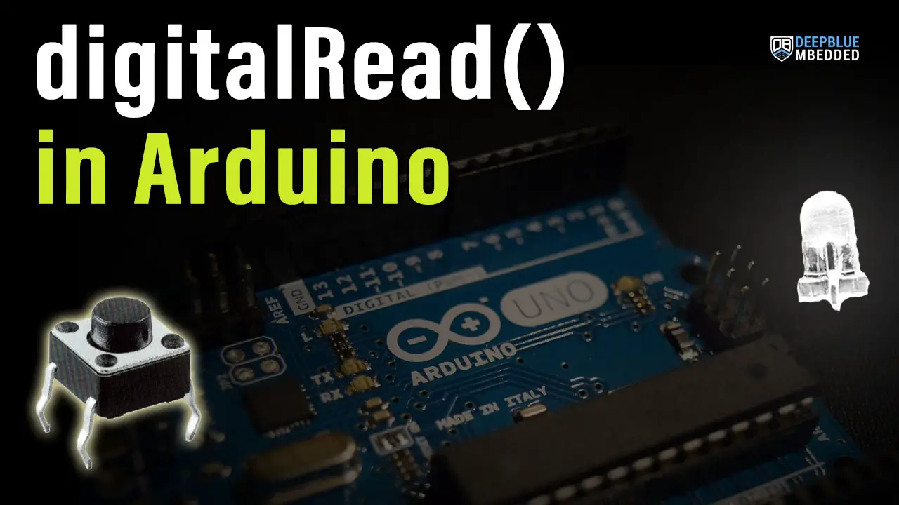
This is a comprehensive guide for Arduino digitalRead in which you’ll learn about Arduino digital input pins and how to configure the pinMode and read the digital state of an Arduino digital input pin. We’ll create a couple of Arduino digital input example projects to practice what we’re going to learn.
We’ll also investigate the digitalRead function’s speed to find out its execution time. And finally, we’ll discuss how to use the Arduino analog input pins as digital input pins. Without further ado, let’s get right into it!
Table of Contents
- Arduino Digital Input Pins
- Arduino pinMode() Function
- Arduino digitalRead Function
- Arduino digitalRead Examples
- Arduino digitalRead Speed
- Arduino digitalRead Analog Pins
- Arduino digitalRead Always High
- Arduino digitalRead Wrap Up
Arduino Digital Input Pins
The Arduino GPIO (digital IO) pins can be configured as digital input pins to be used for reading digital inputs (like push buttons, sensors, etc). In order to configure a digital IO pin as an input, we need to use the pinMode() function. Let’s say we want to configure Arduino’s pin number 2 to be an input pin. Here is how to do it in code.
pinMode(2, INPUT);
And now, we can use the Arduino digitalRead() function to get the pin state ( HIGH or LOW).
pinState = digitalRead(2);
After executing the line of code above, the variable pinState will have the digital state (HIGH or LOW) of the IO pin2 stored in it. You can then do a conditional check, print it, or whatever you need in your application.
Arduino pinMode() Function
The Arduino pinMode() function sets the behavior of a specific digital IO pin to behave as an output pin or an input pin. It can also enable the internal pull-up resistor for input pins if the mode INPUT_PULLUP is selected. However, the mode INPUT will set your IO pin in input mode and explicitly disable the internal pull-up resistor.
The Arduino pinMode() function takes only 2 parameters:
- pin: the Arduino pin number to be configured.
- mode: it can be( INPUT, OUTPUT, or INPUT_PULLUP).
For example, to set pin number 2 to be an input pin. Here is how to do it:
pinMode(2, INPUT);
And if we need to set the Arduino pin number 2 to be an input pin with the internal pull-up resistor enabled, we can use the INPUT_PULLUP mode as shown below.
pinMode(2, INPUT_PULLUP);
To learn more about the Arduino pinMode() function, INPUT_PULLUP, INPUT_PULLDOWN modes, pin floating state, and how to implement internal or external pull-up, it’s highly recommended that you check out the tutorial linked below.

This article will give more in-depth information about the Arduino pinMode() function, INPUT_PULLUP, INPUT_PULLDOWN modes, pin floating state, and how to implement internal or external pull-up
Arduino digitalRead Function
The Arduino digitalRead() function reads the digital state of an input pin ( HIGH or LOW) and return it.
Syntax
digitalRead(pin);
Parameters
pin: the Arduino pin number you want to read
Return
HIGH or LOW (1 or 0)
Example Code
#define BTN_PIN 4

void setup()
{
  pinMode(LED_BUILTIN, OUTPUT);
  pinMode(BTN_PIN, INPUT);
}

void loop()
{
  while(digitalRead(BTN_PIN))
  {
    digitalWrite(LED_BUILTIN, HIGH);
  }
  digitalWrite(LED_BUILTIN, LOW);
}
Leaving an input pin in a floating state can result in the digitalRead() function returning always HIGH, always LOW, or even a randomly changing value HIGH or LOW. Check the Arduino pinMode Tutorial for more information on this.
Arduino digitalRead Examples
Now, let’s test what we’ve learned so far about the Arduino digitalRead function and create a couple of example projects. In the first example, we’ll read the digital state of a pin hooked to a push button and use it to control an LED on an output pin. Next, we’ll read the state of a push button to toggle the LED on and off with every button click.
1. Arduino Button + LED Example
What we’ll implement is called a “momentary button action” in which the LED will turn ON as long the button is held down and it’ll go OFF whenever the button is released. The button will be connected to Arduino’s IO pin 4, and the LED will stay on the same pin 13.
Wiring
Here is how to hook up the external LED output. (note that the LED current limiting resistor is 330Ω). The push button here is connected in a pull-down configuration with a pull-down resistor of 10kΩ.

Example Code
Here is the full code listing for this example.
/*
 * LAB Name: Arduino LED+Button
 * Author: Khaled Magdy
 * For More Info Visit: www.DeepBlueMbedded.com
*/

#define BTN_PIN 4

void setup()
{
  pinMode(LED_BUILTIN, OUTPUT);
  pinMode(BTN_PIN, INPUT);
}

void loop()
{
  while(digitalRead(BTN_PIN))
  {
    digitalWrite(LED_BUILTIN, HIGH);
  }
  digitalWrite(LED_BUILTIN, LOW);
}
Code Explanation
The code example simply set the Builtin-LED IO pin to be output and defines BTN_PIN to be IO pin4 and sets it as an input pin. Then we read the digital state of the Button pin and turn on the LED while the button is pressed, when the button is released, the LED will be driven low again.
This is the button pin definition (assignation)
#define BTN_PIN 4
setup()
in the setup() function, we initialize the digital IO pin ( LED_BUILTIN or pin 13) to be an OUTPUT pin. And the BTN_PIN to be an input pin.
loop()
in the loop() function, we continuously read the state of the button’s pin. While it’s held down (state=1), the LED will be turned ON. When the button is released, the while loop condition breaks and the LED will be driven back to the LOW state.
Simulation
Here is the simulation result for this project on the TinkerCAD simulator.
You can check this simulation project on TinkerCAD using this link.
Testing Results
Here is a demo video for testing this project on my Arduino UNO board.
2. Arduino Button LED Toggle Example
Wiring
Example Code
/*
 * LAB Name: Arduino Button LED Toggle
 * Author: Khaled Magdy
 * For More Info Visit: www.DeepBlueMbedded.com
*/

#define BTN_PIN 4

void setup()
{
  pinMode(LED_BUILTIN, OUTPUT);
  pinMode(BTN_PIN, INPUT);
}

void loop()
{
  if(digitalRead(BTN_PIN))
  {
    digitalWrite(LED_BUILTIN, !digitalRead(LED_BUILTIN));
    delay(500);
  }
}
Code Explanation
#define BTN_PIN 4
digitalWrite(LED_BUILTIN, !digitalRead(LED_BUILTIN));
Which reads the current state of the LED output pin, inverts it, then writes it back to the LED output pin. And that’s how we toggle the LED state.
We also add a moderate delay of 500ms (0.5s) after toggling the LED to allow the user to release the button before taking the same action again and toggling the LED for the next time and so on.
Simulation
Testing Results
Arduino digitalRead Speed
Reading an IO pin state using the Arduino digitalRead function is not immediate, it takes some time which is the execution time of the digitalRead() function itself.
Arduino digitalRead Speed Measurement Test1
We can measure the Arduino digitalRead function’s speed (execution time) using a timer or the timer-based micros() function. Which takes a timestamp of the timer register and converts it to a time unit in µS (microsecond).
Here is the test code that I’ve come up with, which takes a T1 timestamp before calling the digitalRead() function 4 times, then it takes another timestamp T2. Therefore, the total execution time for the 4 function calls = T2 – T1. And to get the execution time for a single digitalRead() function’s call, we’ll divide the (T2-T1)/4 to get the result.
/*
 * LAB Name: Arduino digitalRead Speed Measurement1
 * Author: Khaled Magdy
 * For More Info Visit: www.DeepBlueMbedded.com
*/
#define TEST_PIN 8

unsigned long T1, T2;
double Total;

void setup()
{
  Serial.begin(9600);
  pinMode(TEST_PIN, INPUT);
  // Start The Measurement
  T1 = micros();
  digitalRead(TEST_PIN);
  digitalRead(TEST_PIN);
  digitalRead(TEST_PIN);
  digitalRead(TEST_PIN);
  T2 = micros();
  Total = (T2 - T1)/4;
  // Print The Measured Execution Time
  Serial.print("digitalRead() Execution Time: ");
  Serial.print(Total);
  Serial.println(" µs");
}
void loop() {
  // DO NOTHING
}
After running the code above on my Arduino UNO board, it turned out that the built-in Arduino digitalRead() function’s speed is 4µS exactly. Which is quite a lot of time for just reading a single IO pin’s state.
digitalRead() Execution Time: 4.0µS
This moderately high execution time can be justified if you take a look at the digitalRead() function’s implementation (which is available on GitHub). This turns out to be doing some extra logic, bit mask creation, validity checks, and other operations the reason why it takes this slightly high execution time.
Using the micros() function for the measurement can also skew the results a little bit that’s why I’ve repeated the digitalRead() function call for 4 times and took the average. And I’ll also show you another measurement that I’ve done after this.
Arduino digitalRead Speed Measurement Test2
In this test procedure, I’ll replace the micros() function calls with direct pin access to eliminate the execution time effect of the digitalWrite() function and also avoid any effect introduced by the implementation of the micros() function itself.
Here is the full code listing for this digitalRead speed measurement experiment.
/*
 * LAB Name: Arduino digitalRead Speed Measurement2
 * Author: Khaled Magdy
 * For More Info Visit: www.DeepBlueMbedded.com
*/
#define TEST_PIN 8
int state = 0;
void setup()
{
  pinMode(TEST_PIN, INPUT);
  DDRD = DDRD | 0x08;
}
void loop() {
  noInterrupts(); // Disable Interrupts
  PORTD |= (1 << 3);
  state = digitalRead(TEST_PIN);
  state = digitalRead(TEST_PIN);
  state = digitalRead(TEST_PIN);
  state = digitalRead(TEST_PIN);
  PORTD &= ~(1 << 3);
  interrupts();  // Re-Enable Interrupts
  delay(100);
}
Note that I’m using PORTD bit 3 which corresponds to Arduino digital IO pin number 3. And I’ve also created a critical section around the measurement instructions by disabling the interrupts before it and re-enabling it after measurement completion. To make sure there is nothing affecting the results.
And here’s the signal on the output pin 3 as shown on my DSO (digital storage oscilloscope).

It took around 11.8µs for 4 digitalRead() operations to complete. In other words, the Arduino digitalRead function speed is around 3µs. Which is not very far from the result we got from the first testing setup.
If you don’t have an oscilloscope in your lab yet, you can still perform the same testing and get very similar results in the proteus (ISIS) simulation environment. Here is the result from simulating the code example for this measurement experiment. It’s showing a pulse width of around 11.6µs which is very close to the 11.8µs that I got using my real Arduino UNO board with a real oscilloscope.

Check out this guide tutorial below to help you get started with simulating your Arduino projects in the Proteus simulation environment.

This article will provide more in-depth information about using proteus ISIS for Arduino projects simulation.
Arduino Fast digitalRead
If you’d like to learn how to implement a fast digitalRead using Arduino port manipulation, you definitely need to check out the tutorial below. That explains this topic in detail with a lot of code examples for implementing Arduino direct register access macros.

This article will provide more in-depth information about Arduino port manipulation and direct register access to control IO ports. How to use DDR, PORT, and PIN registers to control IO ports/pins. And also the implementation of fast digitalWrite & digitalRead macros in Arduino.
Arduino digitalRead Analog Pins
Arduino Uno has a total of 14 GPIO pins, out of which 6 pins (from A0 to A5) are analog pins.
The question is can we use Arduino analog pins as digital output pins? The answer is YES, and here is how to do it.
First of all, the ADC is a valuable resource in any microcontroller. Under certain circumstances, you’d sacrifice the analog input channels just to get extra digital IO pins. Sometimes an external IO expander would be a better solution instead of sacrificing the ADC analog input channels.
But let’s say you’ve made your decision and you need to have an extra digital pin or two. And the analog input pins are the only hope you’ve got. Here is how you’d go about implementing this.
Just deal with the analog input pins (A0 – A5) as if they’re normal digital IO pins. This means you first need to call the pinMode() function to set the pin mode to INPUT. And then you can call the digitalRead() function to get the pin state HIGH or LOW. Here is an example code: Note that the A0 pin is assumed to be externally pulled up to Vcc with a 10kΩ resistor.
void setup() {
  pinMode(A0, INPUT);
}

void loop() {
  if(digitalRead(A0) == LOW)
  {
     // Button Is Pressed
  }
  else // If Pin A0 State == HIGH
  {
     // Button Is Released
  }
}

This guide will give more in-depth information about Arduino analog pins and how to use them as digital IO pins for digitalWrite & digitalRead operations.
Arduino digitalRead Always High
One common issue that a lot of readers are facing is having a constant digitalRead return value of HIGH, sometimes a constant LOW, or even a fluctuating reading between HIGH and LOW continuously. This can be due to the fact that you’re leaving the Arduino digital input pin in a floating state which is something you should never allow for an input pin.
You either put the digital input pin in a pull-up or pull-down configuration before attempting to do a digtialRead() for the pin status. It should have a stable IDLE state. Check your connections and make sure you’re already doing the external pull-up or pull-down correctly. Alternatively, you can take advantage of the available Arduino internal pull-up resistors available on all digital input pins.
Parts List
Here is the full components list for all parts that you’d need in order to perform the practical LABs mentioned here in this article and for the whole Arduino Programming series of tutorials found here on DeepBlueMbedded. Please, note that those are affiliate links and we’ll receive a small commission on your purchase at no additional cost to you, and it’d definitely support our work.
Download Attachments
You can download all attachment files for this Article/Tutorial (project files, schematics, code, etc..) using the link below. Please consider supporting my work through the various support options listed in the link down below. Every small donation helps to keep this website up and running and ultimately supports our community.
Arduino digitalRead Wrap Up
To conclude this tutorial, we can say that Arduino digitalRead is only the first step in the Arduino Programming journey. The following tutorials in this series will help you get started with Arduino programming and learn more topics with practical examples and step-by-step explanations.
If you’re just getting started with Arduino, you need to check out the Arduino Getting Started [Ultimate Guide] here.
And follow this Arduino Series of Tutorials to learn more about Arduino Programming.

This is the ultimate guide for getting started with Arduino for beginners. It’ll help you learn the Arduino fundamentals for Hardware & Software and understand the basics required to accelerate your learning journey with Arduino Programming.
FAQ & Answers
Yes, Arduino can read digital input signals using the digital IO pins. You need to set the desired IO pin to be an input pin using the pinMode() function. And then you can read its digital state using the Arduino digitalRead() function.
The Arduino digitalRead() function returns a HIGH or LOW depending on the actual digital input pin state.
The Arduino digitalRead() function takes around 3µs to fully execute.
The Arduino UNO board has 14 digital IO pins, and 6 analog pins that can also be used as digital input pins. So you can practically have 20 digital inputs in Arduino. And you can also use I2C IO expander ICs to get even more digital input output pins.