In this tutorial, we’ll create two Arduino Button Toggle LED Projects and you’ll learn step-by-step how to do it yourself. We’ll also discuss the working of code examples in detail and run the projects in both real-world and simulation environments. Without further ado, let’s get right into it!
Table of Contents
- How To Toggle LED Using Button in Arduino?
- Button Toggle LED Project Wiring Diagram
- Arduino Code – Button Toggle LED Without Debouncing
- Arduino Code – Button Toggle LED With Debouncing
- Button Toggle LED Project Simulation
- Button Toggle LED Project Testing
- Project Wrap Up
How To Toggle LED Using Button in Arduino?
To toggle an LED using a push button in Arduino, we need the following components:
- Arduino Board
- Push Button
- LED
- Resistors (1x 10kΩ and 1x 330Ω)
The toggle action means inverting the digital state of the output pin (or LED). To create an Arduino button toggle action, we’ll follow the steps below:
- Define an output pin (for the LED)
- Define an input pin (for the push button)
- Read the button input pin
- If the button is pressed: flip the pin state
And this is simply what we need to do in order to achieve button toggle action for the LED using Arduino. We’ll create two versions of this project, one without debouncing the push button and another one with a button debouncing technique to eliminate the noise or jitter in the button input signal.
Button Toggle LED Project Wiring Diagram
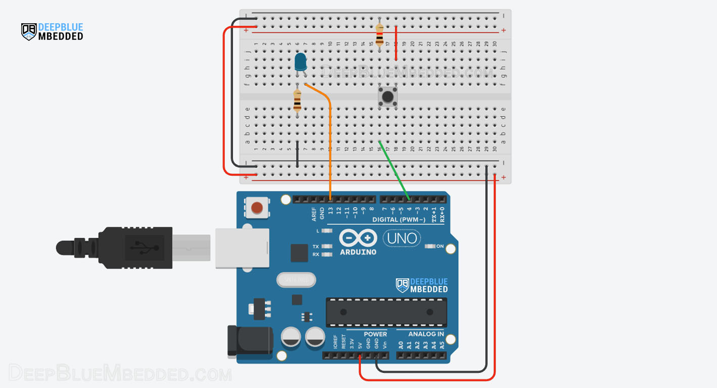
Here is the wiring diagram for this example project. The LED output pin is 13, and the push button input pin is 4.
Arduino Code – Button Toggle LED Without Debouncing
In this example project, we’ll create a button toggle action for an LED output using Arduino. The push button input pin is not denounced in this example, therefore it’s prone to jitter/noise. But for the sake of simplicity, we’ll add a small delay after detecting a button click to eliminate the effect of button bouncing noise.
Code Example
|
1 2 3 4 5 6 7 8 9 10 11 12 13 14 15 16 17 18 19 20 21 22 |
/* * LAB Name: Arduino Button LED Toggle (Not Debounced) * Author: Khaled Magdy * For More Info Visit: www.DeepBlueMbedded.com */ #define BTN_PIN 4 void setup() { pinMode(LED_BUILTIN, OUTPUT); pinMode(BTN_PIN, INPUT); } void loop() { if(digitalRead(BTN_PIN)) { digitalWrite(LED_BUILTIN, !digitalRead(LED_BUILTIN)); delay(500); } } |
Code Explanation
|
1 |
#define BTN_PIN 4 |
|
1 |
digitalWrite(LED_BUILTIN, !digitalRead(LED_BUILTIN)); |
Which reads the current state of the LED output pin, inverts it, then writes it back to the LED output pin. And that’s how we toggle the LED state.
We also add a moderate delay of 500ms (0.5s) after toggling the LED to allow the user to release the button before taking the same action again and toggling the LED for the next time and so on.
Leaving an input pin in a floating state can result in the digitalRead() function returning always HIGH, always LOW, or even a randomly changing value HIGH or LOW. Check the Arduino pinMode Tutorial for more information on this.
This article will give more in-depth information about the Arduino pinMode() function, INPUT_PULLUP, INPUT_PULLDOWN modes, pin floating state, and how to implement internal or external pull-up
Arduino Code – Button Toggle LED With Debouncing
In this second project example, we’ll implement the same button toggle action for an LED using Arduino. But this time, we’ll implement a simple button debouncing technique to eliminate the effect of the input button bouncing.
Code Example
|
1 2 3 4 5 6 7 8 9 10 11 12 13 14 15 16 17 18 19 20 21 22 23 24 25 26 27 28 29 30 31 32 33 34 |
/* * LAB Name: Arduino Button LED Toggle (Debounced) * Author: Khaled Magdy * For More Info Visit: www.DeepBlueMbedded.com */ #define BTN_PIN 4 // Global Variables For Button Reading & Debouncing int ledState = LOW; int btnState = LOW; int lastBtnState = LOW; int lastDebounceTime = 0; int debounceDelay = 50; void setup(){ pinMode(LED_BUILTIN, OUTPUT); pinMode(BTN_PIN, INPUT); } void loop() { int reading = digitalRead(BTN_PIN); if (reading != lastBtnState) { lastDebounceTime = millis(); } if ((millis() - lastDebounceTime) > debounceDelay) { if (reading != btnState) { btnState = reading; if (btnState == HIGH) { ledState = !ledState; digitalWrite(LED_BUILTIN, ledState); } } } lastBtnState = reading; } |
Code Explanation
|
1 |
#define BTN_PIN 4 |
We also define some global variables to save the LED state, and button state, and perform the button debouncing logic.
|
1 2 3 4 5 |
int ledState = LOW; int btnState = LOW; int lastBtnState = LOW; int lastDebounceTime = 0; int debounceDelay = 50; |
If debounce time (defined as 50ms) has passed, we then check if the button state is still the same or if it has changed. If it’s valid, we’ll be sure that it’s not noise and the button is actually pressed by the user. Therefore, we’ll carry on the LED toggle action.
Button Toggle LED Project Simulation
We can test this project’s code examples using any available Arduino simulator environment. Here I’ll show you the simulation results for this project on both TinkerCAD and Proteus (ISIS).
TinkerCAD Simulation
Proteus (ISIS) Simulation
Another extremely powerful simulation environment for Arduino is the Proteus (ISIS) with Arduino add-on library. It can definitely run our test projects for this tutorial. But you won’t feel its power until you need some virtual test equipment like an oscilloscope, function generator, power supply, and advanced SPICE simulation for auxiliary electronic circuitry that you may build around an Arduino microcontroller.
Here is the Arduino project simulation result from the Proteus environment.
Check out the tutorial below to help you get started with simulating your Arduino projects in the Proteus simulation environment.
This article will give more in-depth information about using proteus ISIS for Arduino projects simulation.
Button Toggle LED Project Testing
Parts List
Here is the full components list for all parts that you’d need in order to perform the practical LABs mentioned here in this article and for the whole Arduino Programming series of tutorials found here on DeepBlueMbedded. Please, note that those are affiliate links and we’ll receive a small commission on your purchase at no additional cost to you, and it’d definitely support our work.
Download Attachments
You can download all attachment files for this Article/Tutorial (project files, schematics, code, etc..) using the link below. Please consider supporting my work through the various support options listed in the link down below. Every small donation helps to keep this website up and running and ultimately supports our community.
Project Wrap Up
To conclude this project tutorial, we can say that the button toggle action is pretty much easy to implement and can be used as a software/hardware block in different Arduino projects to control other devices, not only an LED. It’s just the beginning of an endless list of possibilities for what you can do with this knowledge.
If you’re just getting started with Arduino, you need to check out the Arduino Getting Started [Ultimate Guide] here.
And follow this Arduino Series of Tutorials to learn more about Arduino Programming.
For more projects & ideas, check this Arduino Projects resource page.
This is the ultimate guide for getting started with Arduino for beginners. It’ll help you learn the Arduino fundamentals for Hardware & Software and understand the basics required to accelerate your learning journey with Arduino Programming.
FAQ & Answers
The toggle action means inverting the digital state of the output pin (or LED). To create an Arduino button toggle action, we’ll follow the steps below:
1. Define an output pin (for the LED)
2. Define an input pin (for the push button)
3. Read the button input pin
4. If the button is pressed: flip the pin state
The simplest way to implement an Arduino LED toggle is to do the following: (Read the LED pin state, invert it, and write it back to the pin’s output)
digitalWrite(LED_BUILTIN, !digitalRead(LED_BUILTIN));
Toggle state in Arduino is the act of inverting the digital state of the output from 0 to 1 or from 1 to 0.
To eliminate the need for an external pull-up resistor, you can use the Arduino’s internal pull-up resistor with the button instead. In this way, you won’t have to connect an external resistor to the Arduino input pin connected to the button.
