In this project tutorial, we’ll create an Arduino LED Dimmer Project Using Potentiometer & PWM (analog output). You’ll learn how PWM works, and how to create a LED Dimmer with Arduino controlled by a potentiometer. And we’ll simulate and run the project code example to test its functionality. Without further ado, let’s get right into it!
Table of Contents
- LED Dimming With Arduino
- LED Dimmer Project Wiring Diagram
- Arduino Code – LED Dimmer
- LED Dimmer Project Simulation
- LED Dimmer Project Testing
- Project Wrap Up
LED Dimming With Arduino
To create the Arduino LED Dimmer project, we need the following components:
- Arduino Board
- LED
- Resistor (330Ω)
- Potentiometer (10kΩ)

The Arduino LED Dimmer is based on the Arduino PWM output signal that’s used to control the LED brightness and increase or decrease its duty cycle according to the potentiometer (analog input) position.
Arduino boards have several PWM output pins usually. Those pins are designated with a (~) mark next to the pin number on the board. Before discussing how to use the PWM output pins, let’s first define what is the PWM technique and what are the properties of a PWM signal.
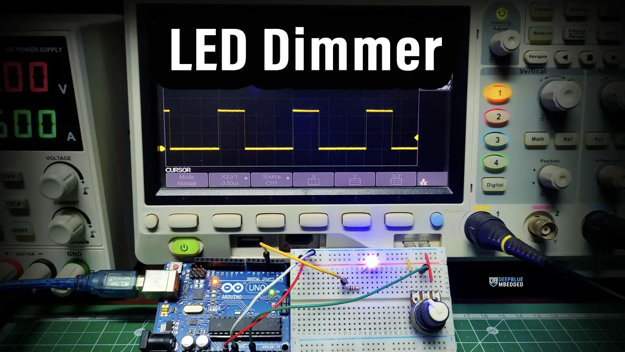
Pulse Width Modulation (PWM) is a technique for generating a continuous HIGH/LOW alternating digital signal and programmatically controlling its pulse width and frequency. Certain loads like (LEDs, Motors, etc) will respond to the average voltage of the signal which gets higher as the PWM signal’s pulse width is increased.

As you can see, the LED gets brighter as the pulse width (duty cycle) increases, and it gets dimmer as the pulse width decreases. And this is typically what we use the PWM output for.
Check the tutorial below to learn more about Arduino PWM. It’s a prerequisite for this project to help you understand the topic in more detail.

This tutorial will provide you with more in-depth information about Arduino PWM output. Starting from the basics of PWM signal, its frequency, duty cycle, and resolution, and will discuss in detail how it works and how to use it in various Arduino control projects.
LED Dimmer Project Wiring Diagram
Here is the wiring diagram for this example showing how to connect the LED output, the potentiometer analog input, and the oscilloscope channel.

Arduino Code – LED Dimmer
In this example project, we’ll control an LED brightness with an Arduino PWM output pin. We’ll use a potentiometer and the analogRead() function to get the potentiometer reading and use it to control the PWM’s duty cycle for LED Dimming.
Here is the full code listing for this example.
/*
 * LAB Name: Arduino LED Dimmer (Potentiometer + PWM)
 * Author: Khaled Magdy
 * For More Info Visit: www.DeepBlueMbedded.com
*/
#define LED_PIN 3

void setup()
{
  pinMode(LED_PIN, OUTPUT);
}

void loop()
{
  analogWrite(LED_PIN, (analogRead(A0)>>2));
}
Code Explanation
First of all, we define the IO pin used for the LED output. It has to be a PWM-enabled IO pin (for UNO: 3, 5, 6, 9, 10, or 11).
#define LED_PIN 3
setup()
in the setup() function, we’ll set the pinMode to be output.
pinMode(LED_PIN, OUTPUT);
loop()
in the loop() function, we’ll read the analog input pin of the potentiometer (which is 10-Bit resolution) and convert it to 8-Bit resolution by dividing by 4 (or right-shifting twice “ >>2”). Now, we’ve mapped the analog input value to the PWM duty cycle range.
Using Arduino analogWrite() function, we’ll write back the ADC scaled reading as a duty cycle for the PWM to control the speed of the motor accordingly.
analogWrite(LED_PIN, (analogRead(A0)>>2));
LED Dimmer Project Simulation
We can test this project’s code example using any available Arduino simulator environment. Here I’ll show you the simulation results for this project on both TinkerCAD and Proteus (ISIS).
TinkerCAD Simulation
You can check this simulation project on TinkerCAD using this link.
Proteus (ISIS) Simulation
Another extremely powerful simulation environment for Arduino is the Proteus (ISIS) with Arduino add-on library. It can definitely run our test projects for this tutorial. But you won’t feel its power until you need some virtual test equipment like an oscilloscope, function generator, power supply, and advanced SPICE simulation for auxiliary electronic circuitry that you may build around an Arduino microcontroller.
Here is the Arduino project simulation result from the Proteus environment.
Check out the tutorial below to help you get started with simulating your Arduino projects in the Proteus simulation environment.

This article will provide you with more in-depth information about using proteus ISIS for Arduino projects simulation.
LED Dimmer Project Testing
Parts List
Here is the full components list for all parts that you’d need in order to perform the practical LABs mentioned here in this article and for the whole Arduino Programming series of tutorials found here on DeepBlueMbedded. Please, note that those are affiliate links and we’ll receive a small commission on your purchase at no additional cost to you, and it’d definitely support our work.
Download Attachments
You can download all attachment files for this Article/Tutorial (project files, schematics, code, etc..) using the link below. Please consider supporting my work through the various support options listed in the link down below. Every small donation helps to keep this website up and running and ultimately supports our community.
Project Wrap Up
To conclude this project tutorial, we can say that you can easily create a LED Dimmer with Arduino PWM output using the analogWrite() function and a PWM output pin. To learn more about Arduino PWM, it’s highly recommended that you check out this Arduino PWM Tutorial. And check the Arduino projects page for more project ideas and code examples.
If you’re just getting started with Arduino, you need to check out the Arduino Getting Started [Ultimate Guide] here.
And follow this Arduino Series of Tutorials to learn more about Arduino Programming.
For more projects & ideas, check this Arduino Projects resource page.

This is the ultimate guide for getting started with Arduino for beginners. It’ll help you learn the Arduino fundamentals for Hardware & Software and understand the basics required to accelerate your learning journey with Arduino Programming.
FAQ & Answers
To make an Arduino LED Dimmer project, you need to use a PWM output pin and an analog input pin (for the potentiometer)
1- Set an IO pin as an output pin using the pinMode function.
2- Continuously read the analog input pin for the potentiometer
3- Map the 10-Bit ADC reading to the range of the 8-Bit PWM’s duty cycle and write the value using the analogWrite() function
If you’re using Arduino’s PWM output to control the LED brightness, the maximum brightness value would be 255, corresponding to a PWM duty cycle of 100%.
One Arduino can power as many LEDs as you want given that you will use an external power supply and a transistor as a switching device. The Arduino itself can’t supply more than 40mA per IO pin; you can’t draw more than 200mA from all Arduino IO pins combined. Therefore, you need an external power source + a transistor to control as many LEDs as your project needs.
You can create an electronic circuit for LED dimming like Timer555-based circuits. Or you can use a microcontroller like Arduino with PWM output to create a LED dimmer application.