In this tutorial, we’ll discuss Arduino Interrupts from the very basic concepts all the way to implementing Arduino interrupt-based systems. We’ll start off by discussing what are interrupts, how they work, and what are different types of interrupts. You’ll learn all Arduino interrupts mechanics and how to properly set up an interrupt-based system and write efficient ISRs (interrupt service routines).
We’ll create a couple of Arduino Interrupt Example Code Projects in this tutorial to practice what we’ll learn all the way through. And finally, we’ll draw some conclusions and discuss some advanced tips & tricks for Arduino interrupts that will definitely help you take some guided design decisions in your next projects. Without further ado, let’s get right into it!
Table of Contents
- How Interrupts Work?
- Types of Interrupts
- Why & When To Use Interrupts?
- Interrupt Service Routines (ISR)
- Arduino Interrupts
- Using Interrupts in Arduino
- Arduino External Interrupt Example
- Guidelines For Writing Efficient Arduino ISRs
- Remarks on Arduino Interrupts
- Arduino Interrupts Wrap Up
How Interrupts Work?
To better understand interrupts in microcontrollers like Arduino (Atmega328p), Let’s consider the following analogy as an example to demonstrate how interrupts actually work.
Interrupts Analogy
First of all, let’s say you are acting as the (CPU) and your main task is to read a book. But your friend can call you on the phone at any moment to check how you’re doing. Therefore, the phone ringing is considered an interrupt, and your answering the phone is the handling of this interrupt signal.
When the phone rings, you need to bookmark or save where you’re currently on the book ( let’s page x, line y). Then, you pick up the phone and get done with it. And you can continue the main work (reading the book) exactly where you left off (page x, line y).
If you’re receiving too many calls or taking too long to service each call, you’ll never progress through the main, and most important, task which is reading the book. And this is exactly why we need to limit the number of interrupts the CPU receives per second and also make the ISR (interrupt service routine) handlers as quick as possible.
Interrupts are side tasks that the CPU needs to handle as soon as they arrive and it should not take too long doing so. Otherwise, the main program execution will greatly slow down and the responsiveness of the whole system will also deteriorate.
Arduino Interrupts Mechanics
The actual interrupt handling mechanism in Arduino (Atmega328p) microcontroller is very similar to the previous analogy example in the previous section. And it goes like this:
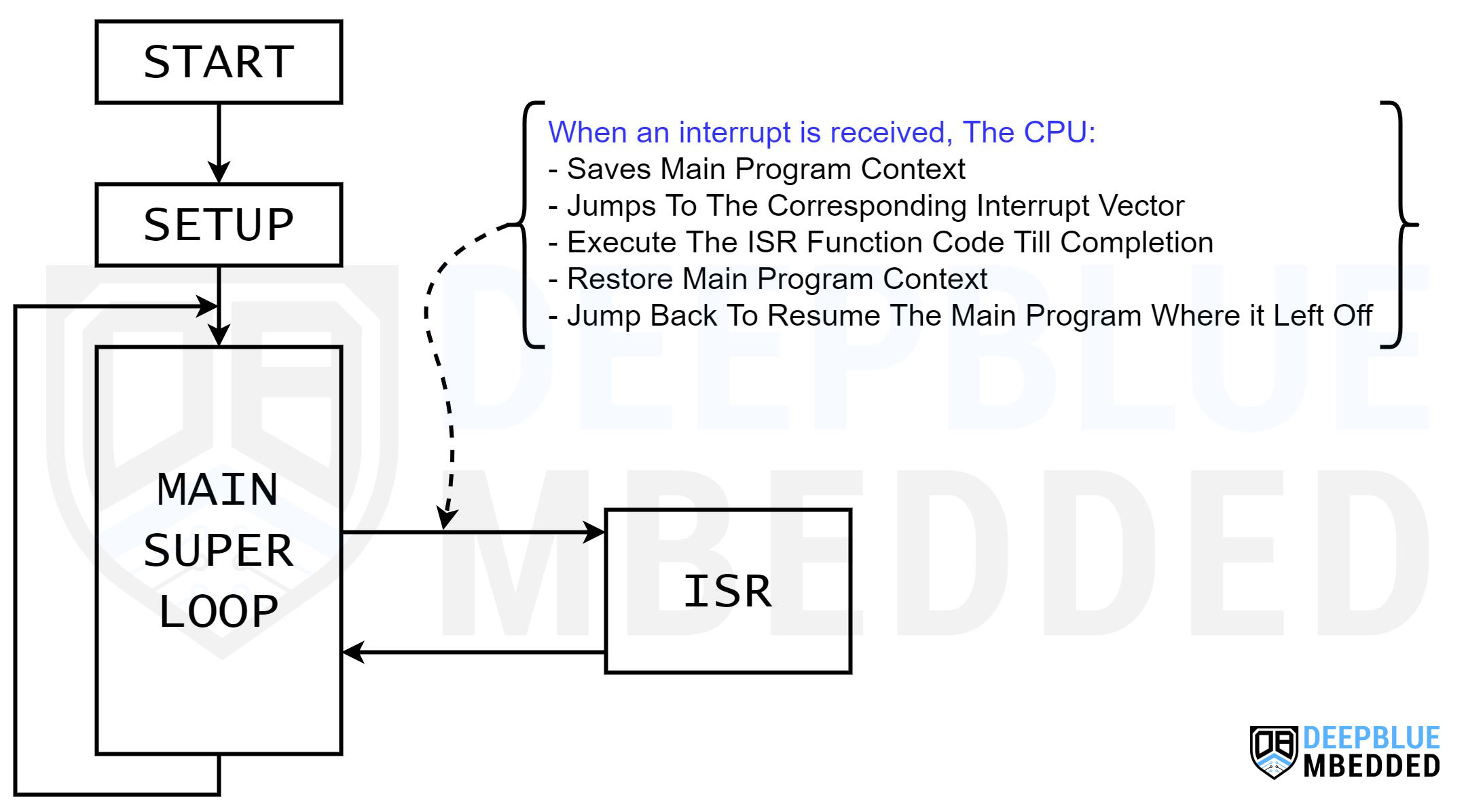
When the microcontroller’s CPU receives an interrupt signal, it pauses the main program execution and saves its current context.
The CPU then jumps to the interrupt vector (address) where the corresponding ISR handler function is located. And starts executing that ISR handler function till completion.
Then, the CPU restores back the context of the main program and jumps back to where it left off the main program. And everything resumes as it used to before the arrival of the interrupt signal.
When a new interrupt is fired, the CPU will immediately be notified and all previous steps will be repeated again. Otherwise, the CPU will keep executing the main program (super loop() function).
Context Saving & Switching
Context saving and restoration is a process that the CPU needs to do just to smoothly switch between main program execution and ISR handlers. It needs to save the current CPU registers, program counter address, and shadow registers. This is the only way the CPU can know where it left off before jumping to the interrupt vector to execute the ISR function located there.
After finishing the execution of the ISR handler function, the CPU needs to remember where it left off the main program to continue from that point. Therefore, context restoration is needed. So it pops up all saved addresses and registers (context) and jumps back to where it left off the main program.
Types of Interrupts
Interrupts can be categorized based on their type into different categories as we’ll discuss in this section. Each interrupt type has a unique set of features, advantages, and disadvantages. And it’s totally dependent on what your actual microcontroller supports.
1. Software & Hardware Interrupts
Software Interrupts
Software interrupts are interrupt signals that can be fired with specific software instructions. Some microcontrollers support native software interrupt instructions while others don’t have dedicated assembly instructions for the CPU to get an interrupt from the software.
Other techniques can be implemented to programmatically enforce an interrupt to the CPU within your software even if it doesn’t have a soft interrupt instruction. This of course requires some workarounds but it’s not that hard to do in general.
A software interrupt can be referred to as a Trap as well. Which is a technique to signal the CPU within the software to change the mode, throw an error, indicate an arithmetic error, or signal the OS.
Hardware Interrupts
Hardware interrupts are generated by hardware peripherals in the microcontroller itself (like Timers, External IRQ pins, UART, SPI, etc.). Hardware modules fire various interrupt signals so the CPU gets notified about it and handles them as quickly as possible.
2. External & Internal Interrupts
Internal Interrupts
Internal interrupts are generated by internal events within the microcontroller itself, such as timers, ADC, UART, or any other peripheral events.
External Interrupts
External interrupts on the other hand are triggered by external signals applied to specific pins of the microcontroller. Those pins are usually referred to as IRQ pins (interrupt request pins). Which directly fire interrupt signals to the CPU when a certain external event occurs, that’s why those interrupts are known as external interrupts.
The most common types of IRQ pins are dedicated external interrupt pins and IOC (interrupt-on-change) pins. The difference is that dedicated external IRQ pins have separate interrupt vectors, while IRQ IOC pins share a common interrupt signal and you have to manually check which pin state has changed and caused that IOC global flag to fire the interrupt.
3. Vectored & Non-Vectored Interrupts
Vectored Interrupts
A vectored-quantity in physics is a quantity that has a magnitude and a direction. Similarly, a vectored interrupt is an interrupt signal that has a specific address (vector) that points to the memory location where its ISR handler is located. So when an interrupt is fired, the CPU goes directly to the corresponding interrupt vector to execute the respective ISR handler.
This means, in vectored-interrupts systems, we’ll have a dedicated ISR handler for each interrupt signal that we’re using in the system. For example, here is how to handle two interrupt sources (INT0, and TMR1) in a vectored-interrupts system.
|
1 2 3 4 5 6 7 8 9 |
ISR (TIMER1_vect) { // Handle The Timer1 Interrupt } ISR (INT0_vect) { // Handle The External INT0 Interrupt } |
As you might have noticed, there are two separate ISR handlers for each interrupt signal source and each one has its own vector (address).
Non-Vectored Interrupts
Non-Vectored Interrupts, on the other hand, share a common global interrupt vector (address) for all interrupt signal sources. This means you need to manually check which interrupt has occurred and service them after validating the interrupt flag bits. This has to be done each time any interrupt is fired.
Here is an example of how to handle two interrupt sources (INT0, and TMR1) in a non-vectored interrupts system.
|
1 2 3 4 5 6 7 8 9 10 11 12 13 |
ISR(void) { if(INT0IF) { // Handle The External INT0 Interrupt } if(TMR1IF) { // Handle The External INT0 Interrupt } .. .. } |
As you might have noticed, there is only one global ISR handler for all interrupt sources. And we had to manually check the interrupt flag bits (INT0IF & TMR1IF) to detect which interrupt has occurred and service it accordingly.
The Arduino UNO’s microcontroller (Atmega328p) has a vectored-interrupt system.
4. Maskable & Non-Maskable Interrupts
Maskable Interrupts
Maskable interrupts can be programmatically enabled or disabled using dedicated interrupt enable/disable bits. Maskable interrupts can be enabled or disabled during runtime using software instructions which can be helpful in a lot of applications.
Non-Maskable Interrupts
Non-Maskable interrupts on the other hand are always enabled by default and there is no way to disable them by software instructions in runtime. Things like RESET, WDT (watchdog timer), BOD (brown-out detection or power failure), and hardware failures are common non-maskable interrupts that you can’t disable in software.
Why & When To Use Interrupts?
We typically use interrupts in embedded systems as a better alternative for event polling mechanism which keeps the CPU blocked in a busy-waiting state waiting for something to happen. Interrupts on the other hand saves the CPU time from being wasted in unnecessarily polling events & peripherals. And provides a near-immediate response to various events instead.
But there are so many other reasons to use interrupts in embedded systems other than replacing polling instructions. Here are some other situations and use cases for interrupts:
Time-Critical Tasks: When certain tasks require immediate attention and cannot be delayed by the main program flow, interrupts provide a way to handle them immediately.
Real-Time Event Handling: Interrupts allow quick responses to external events, such as button clicks, sensor readings, or communication signals, enabling the microcontroller to react instantly.
Efficient CPU Time Utilization: By using interrupts, the microcontroller can multitask and handle multiple events concurrently, optimizing resource utilization and ensuring smooth operation.
Precise Timing Requirements: For tasks that require precise timing or synchronization, timer interrupts can be used to trigger actions at specific moments or time intervals.
Energy Efficiency: Interrupts enable the microcontroller to stay in a low-power mode until an external event occurs, reducing power consumption and prolonging battery life in portable devices.
While interrupts make the system more responsive and provide a near-instant response to various internal & external events, it also adds to the system’s complexity and sometimes overload the CPU if not reasonably designed (set up). Using Interrupts also reduces the predictability of the system and makes it harder to analyze the dynamic behavior (timing) of the system.
Interrupt Service Routines (ISR)
The ISR (Interrupt Service Routine) is a dedicated function that the CPU executes in response to an interrupt event. It is responsible for handling the specific task associated with the interrupt signal. When an interrupt occurs, the microcontroller jumps to the ISR handler function, executes it, and returns to where it left off the main program.
ISRs should be kept short and efficient to minimize the disruption of the main program flow. They should focus on completing the critical tasks associated with the interrupt and avoid unnecessary delays or time-consuming operations.
An ISR handler function should have a unique identifier that designates an ISR function from a general-purpose user-defined function. This varies from one toolchain to another, each compiler has its own syntax to define an ISR function (whether it’s vectored or non-vectored ISR handler).
As stated earlier, Arduino’s Atmega328p microcontroller has a vectored-interrupt system. This means we need to define an ISR handler function for each interrupt signal being used in the system. Here is an example of the Timer1 overflow interrupt handler definition.
|
1 2 3 4 |
ISR(TIMER1_OVF_vect) { // Handler Timer1 OverFlow Interrupt } |
Similarly, other interrupt signals can be handled by ISR functions written in the same way as the one shown above. Which we’ll see in this tutorial’s examples hereafter.
Arduino Interrupts
In this section, we’ll shift the focus from general interrupts working principles and mechanisms to discuss Arduino Interrupts in detail. We’ll explore Arduino interrupt types, available features, and more other details.
1. Arduino Software Interrupts
It’s stated clearly in the Arduino UNO’s Atmega328p datasheet that it doesn’t have a dedicated assembly instruction to trigger a software-generated interrupt signal. But as we’ve stated earlier, we can still implement some workarounds to fire software-generated interrupt signals.
One technique to generate a software interrupt is clearly stated in the datasheet itself. Which is to enable any external interrupt pin (IRQ) and set it as an output pin. Writing to any pin of these will trigger an interrupt, and that’s how we get a software-generated interrupt even if it’s not supported by the microcontroller.
Check this tutorial below for more information about Arduino Software Interrupts and to get some code examples as well as some useful tips and tricks.
This article will give more in-depth information about Arduino Software Interrupts, how to generate software interrupts in Arduino, and will also provide an example code for Arduino software interrupts generation.
2. Arduino Hardware Interrupts
The Arduino hardware peripherals have the ability to generate various interrupt signals to the CPU, which include but are not limited to the following hardware interrupt signals:
- RESET: External pin, power-on reset, brown-out reset, and watchdog system reset
- INTx: External interrupt request pins
- PCINTx: Pin-change interrupts
- WDT: Watchdog timer interrupt
- TIMERx: Timers (overflow, compare match A & B, and capture) Events
- UART: UART Rx & Tx interrupts
- SPI: SPI Rx & Tx interrupts
- I2C: TWI interrupt
- ADC: ADC interrupt
- and more…
The full list of hardware interrupt signals supported by the Atmega328p microcontroller can be found in the datasheet. We’ll only use the INTx external interrupt request (IRQ) pin in this tutorial’s examples. Later on, we’ll explore other hardware interrupts & how to handle them in separate future tutorials in this Arduino Programming Series.
3. Arduino Interrupts Priority
Interrupt priority affects the overall system in only one situation. Which is when two interrupts are fired at the exact same time or the CPU found more than one interrupt flag raised at the same time. Only then, the interrupt priority rule decides which interrupt gets serviced first.
The Arduino interrupts system doesn’t support explicit interrupt priority assignation. However, interrupts are executed based on their interrupt vector address, the lower the address the higher the priority.
By relocating and re-arranging the interrupt vector table, we can change the interrupt priorities to match the need. The default interrupt vector table is found in the datasheet and we’ll check it together later on in this tutorial.
4. Arduino Interrupts Nesting
Interrupt nesting is having interrupts to interrupt the execution of the current interrupt handler (ISR). There is a control bit that enables or disables this feature. When enabled, interrupts can get interrupted by other interrupt signals. After completion, the CPU will restore context and keep servicing all interrupt requests till completion, then it gets back to the main context (program flow).
We’ve always learned that Interrupts Nesting is Evil and we should never release software with nested interrupts enabled. However, it can be very helpful for debugging, assessment, and measurements. But it makes the system insanely unpredictable, and you can easily end up having your CPU servicing interrupts all the time without making progress in running the main program at all.
There is no guarantee that your system will run as expected without getting stuck processing endless chains of interrupt requests. Even safety mechanisms like WDT and such won’t help us get out of such a situation.
All in all, it’s what it’s and you only need to know that it does exist and we can enable interrupts to interrupt each other. And this is done by writing to the I-bit in the status register (SREG) as stated in the datasheet.
Using Interrupts in Arduino
Now, let’s see how to use Interrupts in Arduino, which functions are associated with interrupts in Arduino, IRQ pins, trigger modes, and much more.
1. Arduino Interrupt Pins
Speaking of the dedicated IRQ pins (external interrupt pins) in Arduino, they are different from one Arduino board to another. Here is a summarized table for the external interrupt pins available in each Arduino board.
| Arduino Board | External Interrupts Pins |
|---|---|
| Arduino Uno, Nano, Mini | 2, 3 |
| Arduino Mega | 2, 3, 18, 19, 20, 21 |
| Arduino Micro, Leonardo | 0, 1, 2, 3, 7 |
| Arduino Zero | All IO pins (except pin4) |
| Arduino Due | All IO pins |
Let’s take Arduino UNO as an example, it’s got (pins 2 & 3) that correspond to external interrupts (INT0 & INT1) respectively. Note that the interrupt vector number is different than the Arduino IO pin number itself. For this, we use the digitalPinToInterrupt() function that maps the IO pin number to the respective interrupt vector number automatically for us.
The PCINT (pin-change interrupt) is available in all IO pins across the entire Arduino boards list but you need to check the target microcontroller’s datasheet for further details regarding the pin-change interrupts.
2. Interrupt Trigger Modes
The Arduino external interrupt pins fire an interrupt when the digital state of the associated pin has changed. The pin change event that triggers an interrupt can be configured to have one of the following modes:
- RISING: Interrupt fires when the signal goes from LOW to HIGH
- FALLING: Interrupt fires when the signal goes from HIGH to LOW
- CHANGE: Interrupt fires when the signal changes (LOW -> HIGH or HIGH -> LOW)
- LOW: Interrupt fires whenever the signal is held LOW

This gives us (programmers) the flexibility to choose the pin change mode that suits the application we’re working on. Each interrupt trigger mode is useful in a particular system configuration. And below is an example to demonstrate this.
3. Arduino Interrupt Vectors Names
As stated earlier, interrupt vectors are the addresses for different ISR handlers one for each interrupt signal. We need to know the name of the interrupt vector associated with the interrupt signal that we’d like to use & write an ISR handler for.
Therefore, you can reference the Arduino interrupt vector table below which includes the interrupt vector names that you can use in code.
| Vector No. | Program Address | Vector Name | Interrupt Definition |
|---|---|---|---|
| 2 | 0x002 | INT0_vect | External interrupt request 0 |
| 3 | 0x0004 | INT1_vect | External interrupt request 1 |
| 4 | 0x0006 | PCINT0_vect | Pin change interrupt request 0 |
| 5 | 0x0008 | PCINT1_vect | Pin change interrupt request 1 |
| 6 | 0x000A | PCINT2_vect | Pin change interrupt request 2 |
| 7 | 0x000C | WDT_vect | Watchdog time-out interrupt |
| 8 | 0x000E | TIMER2_COMPA_vect | Timer/Counter2 compare match A |
| 9 | 0x0010 | TIMER2_COMPB_vect | Timer/Counter2 compare match B |
| 10 | 0x0012 | TIMER2_OVF_vect | Timer/Counter2 overflow |
| 11 | 0x0014 | TIMER1_CAPT_vect | Timer/Counter1 capture event |
| 12 | 0x0016 | TIMER1_COMPA_vect | Timer/Counter1 compare match A |
| 13 | 0x0018 | TIMER1_COMPB_vect | Timer/Counter1 compare match B |
| 14 | 0x001A | TIMER1_OVF_vect | Timer/Counter1 overflow |
| 15 | 0x001C | TIMER0_COMPA_vect | Timer/Counter0 compare match A |
| 16 | 0x001E | TIMER0_COMPB_vect | Timer/Counter0 compare match B |
| 17 | 0x0020 | TIMER0_OVF_vect | Timer/Counter0 overflow |
| 18 | 0x0022 | SPI_STC_vect | SPI serial transfer complete |
| 19 | 0x0024 | USART_RX_vect | USART Rx complete |
| 20 | 0x0026 | USART_UDRE_vect | USART, data register empty |
| 21 | 0x0028 | USART_TX_vect | USART, Tx complete |
| 22 | 0x002A | ADC_vect | ADC conversion complete |
| 23 | 0x002C | EE_READY_vect | EEPROM ready |
| 24 | 0x002E | ANALOG_COMP_vect | Analog comparator |
| 25 | 0x0030 | TWI_vect | 2-wire serial interface (I2C) |
| 26 | 0x0032 | SPM_READY_vect | Store program memory ready |
4. Arduino ISR Handlers
To write an ISR handler function in Arduino, you need to name it ISR(vector_name) and include the vector name in the space of the argument. The vector name for each interrupt signal in Arduino can be found in the table shown above.
And here is an example of an ISR handler function to the Timer1 overflow interrupt signal.
|
1 2 3 4 |
ISR(TIMER1_OVF_vect) { // Handle Timer1 Overflow Interrupt Here.. } |
And here is another example of an ISR handler function to the INT0 external interrupt IRQ pin (IO pin2).
|
1 2 3 4 |
ISR(INT0_vect) { // Handle INT0 External Interrupt Here.. } |
And so on for any other interrupt signal that you’d like to use & write an ISR handler for.
5. Arduino attachInterrupt() Function
The Arduino attachInterrupt() function is used to enable the external interrupt (IRQ) pins only (INT0 & INT1).
Syntax
|
1 2 |
attachInterrupt(interrupt, ISR, mode); attachInterrupt(digitalPinToInterrupt(pin), ISR, mode); // More Recommended |
Parameters
interrupt: the number of the interrupt vector ( int).
pin: the pin number.
ISR: the ISR handler function to call when the interrupt occurs. This function must take no parameters and return nothing.
mode: defines when the interrupt should be triggered. Four constants are predefined as valid values:
- RISING to trigger when the pin goes from low to high,
- FALLING for when the pin goes from high to low.
- CHANGE to trigger the interrupt whenever the pin value changes
- LOW to trigger the interrupt whenever the pin is low,
The Due, Zero and MKR1000 boards allow also:
- HIGH to trigger the interrupt whenever the pin is high.
Example Code
|
1 2 3 4 5 6 7 8 9 10 11 12 13 14 15 16 17 18 |
#define LED_PIN 13 #define INT0_PIN 2 volatile byte state = LOW; void INT0_ISR() { state = !state; } void setup() { pinMode(LED_PIN, OUTPUT); pinMode(INT0_PIN, INPUT_PULLUP); attachInterrupt(digitalPinToInterrupt(INT0_PIN), INT0_ISR, CHANGE); } void loop() { digitalWrite(LED_PIN, state); } |
6. Arduino detachInterrupt() Function
The Arduino detachInterrupt() function is used to disable external interrupts (INTx) if being enabled earlier. This can be really useful if you no longer need the external interrupt pin in your application, it’s better to offload the CPU by shutting down interrupt sources that are no longer needed.
Syntax
|
1 2 |
detachInterrupt(interrupt); detachInterrupt(digitalPinToInterrupt(pin)); // More Recommended |
Parameters
interrupt: the number of the interrupt vector to be disabled ( int).
pin: the pin number of the interrupt to disable.
7. Global Interrupts (Enable / Disable)
Sometimes, under certain circumstances, you may need to have a critical section in your code. Which is usually a couple of instructions that you want the CPU to run through without getting interrupted. This can be achieved by disabling and re-enabling the global interrupts in the microcontroller.
Arduino (Atmega328p) has a global interrupt enable/disable control bit that you can use for this purpose. There are two wrapper functions for this functionality that you can use instead of direct bit manipulation.
- interrupts(): Re-enables global interrupts after being disabled.
- noInterrupts(): Disables global interrupts.
Keep in mind that you should minimize the utilization of this feature as much as possible. And it’s going to disrupt the timing functions (like millis, micros, and delay functions). Check out the tutorial below to learn more about Arduino global interrupts control functions ( interrupts, noInterrupts, sei, and cli).
This article will give more in-depth information about Arduino global interrupts control using the Arduino noInterrupts, sei() & cli() functions.
Arduino External Interrupt Example
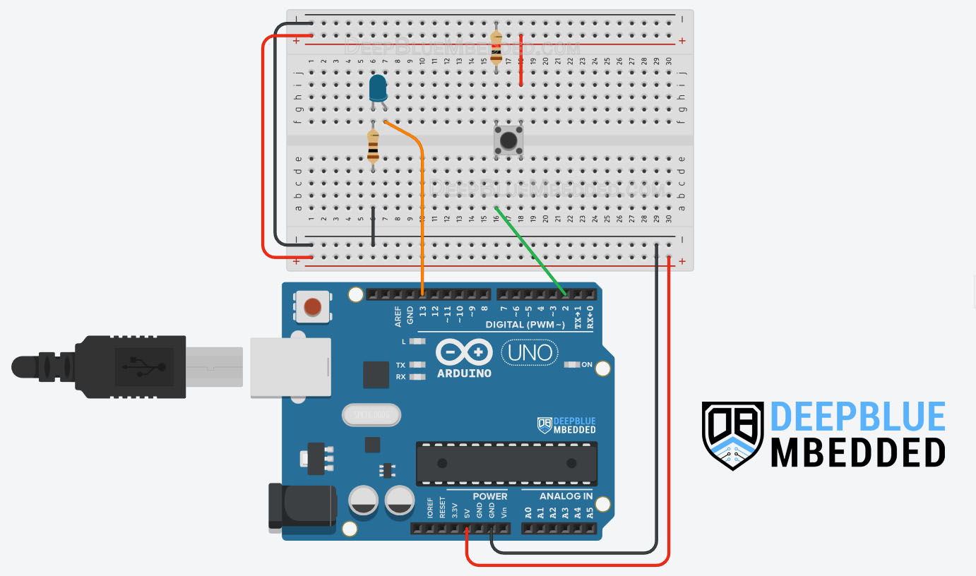
In this example project, we’ll test Arduino external interrupt pins & write an ISR function to handle it. We’ll use INT0 interrupt to toggle an LED output on every rising edge on the external interrupt input pin (hooked to a push button).
Wiring
Here is the wiring diagram for this example showing how to connect the LED output, and the push button to the interrupt input pin (INT0 = pin2).
Arduino Interrupt Example Code
Here is the full code listing for this Arduino External Interrupt Example.
|
1 2 3 4 5 6 7 8 9 10 11 12 13 14 15 16 17 18 19 20 21 22 23 24 |
/* * LAB Name: Arduino External Interrupt Demo * Author: Khaled Magdy * For More Info Visit: www.DeepBlueMbedded.com */ #define LED_PIN 13 #define BTN_PIN 2 void INT0_ISR(void) { digitalWrite(LED_PIN, !digitalRead(LED_PIN)); } void setup() { pinMode(LED_PIN, OUTPUT); pinMode(BTN_PIN, INPUT); attachInterrupt(digitalPinToInterrupt(BTN_PIN), INT0_ISR, RISING); } void loop() { // Do Nothing } |
Code Explanation
We first need to define the IO pins to be used for the LED output & push button input (INT0 external interrupt pin = IO pin2).
|
1 2 |
#define LED_PIN 13 #define BTN_PIN 2 |
INT0_ISR()
This is the ISR handler function for the INT0 external interrupt in which we’ll only do a LED toggle action. For each RISING edge on the external interrupt pin (push button), the CPU will execute this ISR function which will toggle the output LED.
|
1 2 3 4 |
void INT0_ISR(void) { digitalWrite(LED_PIN, !digitalRead(LED_PIN)); } |
setup()
in the setup() function, we’ll initialize the IO pins to be used as input & output using the pinMode() function to set their modes.
|
1 2 |
pinMode(LED_PIN, OUTPUT); pinMode(BTN_PIN, INPUT); |
Then we’ll enable the external interrupt for the INT0 (pin2) using the attachInterrupt() function & set it to trigger on RISING edge events only.
|
1 |
attachInterrupt(digitalPinToInterrupt(BTN_PIN), INT0_ISR, RISING); |
loop()
in the loop() function, nothing needs to be done.
TinkerCAD Simulation
You can check this simulation project on TinkerCAD using this link.
Testing Results
This example project is a very good example to showcase the Button Bouncing issue & how it can affect your Arduino projects. And it also shows you that we can’t always rely on results from the simulation environment only as it’s not going to simulate such real-world random events and noise.
Note that this example project will behave in a weird way due to an issue that’s commonly known as “Button Bouncing“. This is simply a random event due to the button’s mechanical contacts bouncing, which results in some glitches or unintended pulses being injected into the digital input pin causing it falsely trigger the interrupt multiple times “randomly”.
Despite the fact that there are so many software button debouncing techniques (algorithms) that you can learn about from the guide below, it still won’t protect an external interrupt pin because the hardware bouncing is sending a random triggering signal to the interrupt circuitry. The best way to deal with it and prevent false interrupt triggering is to use hardware button debouncing which is also demonstrated in the guide tutorial below with a lot of examples.
This article will provide you with more in-depth information about Arduino button debouncing techniques both hardware & software methods. With a lot of code examples & circuit diagrams.
Guidelines For Writing Efficient Arduino ISRs
Interrupts provide a very efficient way for the CPU to immediately respond to various internal & external events as soon as they arrive. However, having too many interrupts in your system and non-careful implementation for ISR handlers can hold your system back or cause it to potentially fail in many cases.
I remember working on an Automotive ECU that had a microcontroller that was receiving 10k interrupts per second to run the main data sampling & control loop, plus multiple other thousands of interrupts for other sensing & communication purposes. And you won’t be surprised to know that the CPU load was in the 90s% of course.
The nature of the system dictated to have such an insane amount of interrupt signals to the CPU each and every second, and we can’t change that while maintaining the measurement resolution & control frequency. But we can, however, optimize our ISR handlers and we actually did. And that alone brought the CPU load down to 60-ish%.
A high rate of interrupt signals to the CPU every second combined with long execution time for the ISR handler functions for those interrupts, will result in a High overall CPU load. The higher the CPU load is, the less time the CPU spends executing useful code (the main program loop).
At 100% CPU load, the CPU will no longer execute the main program and it’ll be 100% of the time executing ISR functions and still it’s going to miss a lot of them and won’t even service them in a timely manner.
Keep it short
Try to make the ISR handler function as short as possible and avoid bloating it with a lot of logic operations and other stuff. Just keep it as simple as possible and, if needed, you can raise a global flag, check in the main program, and use it for logic activation to call a separate function that handles whatever logic you need to do. There are so many other ways to optimize the size of an ISR handler function and make it much smaller and quicker.
Make it as fast as possible
As we’ve illustrated earlier, you always need to have very fast ISR handler functions. We don’t want to spend so much time processing each interrupt request. So avoid doing heavy arithmetic & floating-point operations in ISR handler functions as much as possible.
You need also to avoid serial communication functions, polling variables & flags, and any other kind of low-speed operations inside ISR handler functions. And here is a simple example to demonstrate how can we accelerate the ISR execution without affecting the overall system functionality.
We’ll read the ADC using a timer interrupt each 20ms (50Hz update rate) and convert the reading to analog voltage and print it to the serial port. Here is how to do it without caring about the ISR speed.
|
1 2 3 4 5 6 7 8 9 10 11 12 13 14 15 16 17 18 19 20 21 22 23 24 25 26 27 28 29 30 31 32 |
/* * LAB Name: Arduino ADC + Timer ISR * Author: Khaled Magdy * For More Info Visit: www.DeepBlueMbedded.com */ volatile float Voltage; ISR(TIMER1_OVF_vect) { TCNT1 = 25535; Voltage = (analogRead(A0) * 5) / 1023; Serial.print("Voltage = "); Serial.print(Voltage); Serial.println(" v"); } void setup() { TCCR1A = 0; // Init Timer1 TCCR1B = 0; // Init Timer1 TCCR1B |= B00000010; // Prescalar = 8 TIMSK1 |= B00000001; // Enable Timer Overflow Interrupt TCNT1 = 25535; Serial.begin(9600); } void loop() { // Do Nothing } |
And here is how to perform the same functionality but with a much better optimized ISR implementation.
|
1 2 3 4 5 6 7 8 9 10 11 12 13 14 15 16 17 18 19 20 21 22 23 24 25 26 27 28 29 30 31 32 33 34 35 36 37 38 39 |
/* * LAB Name: Arduino ADC + Timer ISR (Optimized) * Author: Khaled Magdy * For More Info Visit: www.DeepBlueMbedded.com */ volatile float Voltage; volatile int AN0_RawADC; volatile bool TimerTick = 0; ISR(TIMER1_OVF_vect) { TCNT1 = 25535; AN0_RawADC = analogRead(A0); TimerTick = 1; } void setup() { TCCR1A = 0; // Init Timer1 TCCR1B = 0; // Init Timer1 TCCR1B |= B00000010; // Prescalar = 8 TIMSK1 |= B00000001; // Enable Timer Overflow Interrupt TCNT1 = 25535; Serial.begin(9600); } void loop() { if(TimerTick) { Voltage = (AN0_RawADC * 5) / 1023; Serial.print("Voltage = "); Serial.print(Voltage); Serial.println(" v"); TimerTick = 0; } } |
The optimized ISR handler delegates the serial print operations to the main loop function using a synchronization flag ( TimerTick). And I’ve also removed the floating-point calculation of the voltage from the ISR and moved it to the main loop function as well.
The ISR only takes the ADC reading and saves it in a global flag and that’s it. The main loop function will do the math when the CPU is ready and send the results over the serial port. It’s exactly the same behavior as the non-optimized version but it’s so much faster.
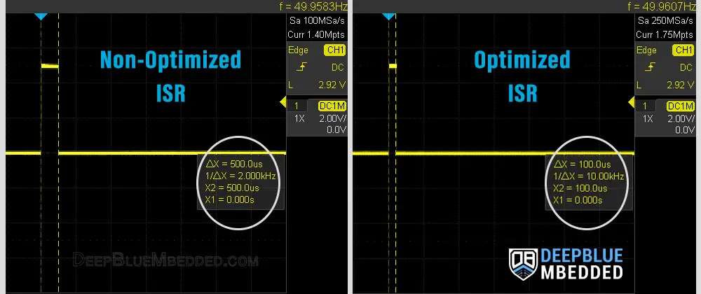
The execution time measurement for the non-optimized ISR handler came to around 500μs, while the optimized version of the ISR takes around 100μs. Which is a 5x times less CPU time utilization without sacrificing anything at all. Here are the execution time measurement results from my oscilloscope.
You can run the tests on your own using a virtual oscilloscope in Arduino Proteus Simulation Environment. And using the technique illustrated in this ADC Tutorial For analogRead Function Speed Measurement. You can use the same code to measure the execution time of ISR handlers and compare the results on your side.
No delays in ISR Handlers
Needless to say that you should not use any sort of delay functions within an ISR handler function. It’ll simply increase the execution time of the ISR for no reason as it can be avoided in the first place with more careful implementations.
Try to find an alternative way to achieve the timing behavior you want without using a delay within any ISR handler function. We’ll discuss more techniques to do this efficiently in this Arduino Programming Series of Tutorials.
Variables used in ISRs must be volatile
Variables used within ISR handler functions must be defined as volatile to protect them from being discarded (optimized out) by the compiler during the code compilation process. Compilers tend to remove global variables that are only used inside ISRs because they think those variables are not used anywhere in the code. And here is an example to demonstrate this.
Consider the following code example.
|
1 2 3 4 5 6 7 8 9 10 11 12 13 14 15 16 17 18 19 |
#define BTN_PIN 2 volatile int counter = 0; void INT0_ISR(void) { counter++; } void setup() { pinMode(BTN_PIN, INPUT); attachInterrupt(digitalPinToInterrupt(BTN_PIN), INT0_ISR, RISING); } void loop() { // Do Nothing } |
In the code above, the ISR function increments the global variable counter each time it gets executed. But the INT0_ISR function itself is not called anywhere in the code. The CPU jumps to it whenever a hardware interrupt signal is fired.
That’s why the compiler thinks this variable is not used because no one is calling the INT0_ISR function in the whole program. Therefore, it’s going to remove it during the code optimization step. But defining the variable as volatile will protect it against this anyway. And that’s why you need to do it as well.
Timing Functions in ISRs
When working with interrupts, it’s important to remember not to use time-related functionalities within your interrupt routines. Let’s explore the details of the four main time functions and their behavior in interrupts:
- delay(): The delay() function relies on interrupts, so it won’t function properly within an ISR handler function. It’s crucial to keep interrupts fast, and using delay() inside interrupts is not recommended by any means.
- delayMicroseconds(): While delayMicroseconds() would work as expected, it’s generally advised to avoid using it within interrupts. Prolonged execution in an interrupt can introduce various problems, as discussed earlier.
- millis(): This function returns the time elapsed since the Arduino program started, measured in milliseconds. However, inside an ISR, other interrupts are temporarily halted, so the value returned by millis() will remain unchanged within the interrupt function. While the last stored value will be correct, it won’t increase during the execution of the interrupt function. And the CPU may get stuck waiting for it to change, potentially forever.
- micros(): Similar to millis(), This function returns the elapsed time but in microseconds. At the start of an interrupt, micros() would work just as fine. However, after some time, the accuracy of micros() may be compromised, leading to a potential drift whenever micros() is used thereafter. Again, the key advice is to keep your interrupts short and fast to avoid issues.
In summary, it’s best to avoid relying on these time functions within ISR handler functions. If you need to compare durations or debounce a button, it’s possible to implement such logic in your main code rather than within the interrupt service routine. Interrupts should primarily be used to instantly notify changes in the monitored signals (interrupt sources).
Remarks on Arduino Interrupts
Before concluding this tutorial, I’d like to highlight some interesting points about Arduino interrupts that you need to know. This will help you take guided design decisions & prevent potential issues while working on your next Arduino projects.
Arduino Interrupts Latency & Response Time

Context saving and restoration is a process that the CPU needs to do just to smoothly switch between main program execution and ISR handlers. It needs to save the current CPU registers, program counter address, and shadow registers. This is the only way the CPU can know where it left off before jumping to the interrupt vector to execute the ISR function located there.
After finishing the execution of the ISR handler function, the CPU needs to remember where it left off the main program to continue from that point. Therefore, context restoration is needed. So it pops up all saved addresses and registers (context) and jumps back to where it left off the main program.
Context saving and switching take time for the CPU to do and we call it interrupt latency. And it happens every time an interrupt signal is received, so if your system is set up in such a way that the CPU receives thousands of interrupts per second, you definitely need to assess the effect of interrupt latency & its contribution to the whole CPU load measurement.
This topic is demonstrated in detail with a couple of measurement techniques in the tutorial linked below which is highly recommended to read, so make sure to check it out.
This article will provide you with more in-depth information about interrupt latency & response time. With a couple of techniques for interrupt latency measurement with Arduino code examples.
Arduino Interrupts & Unpredictability
This was stated earlier in this tutorial, but I’d like to highlight it again. Using interrupts adds to the overall unpredictability of your system’s dynamic (timing) behavior and makes it harder to analyze.
Using excessive interrupt rates will dramatically load the CPU and potentially cause it to fail, miss deadlines, and mess up the timing behavior and requirements. So you not only need to carefully implement & optimize ISR handler functions, but you also need to question the usage of interrupts in the first place and if there is a better alternative or not.
Here is an example: using an optical encoder sensor to measure a motor’s speed, can be achieved using interrupts. But it’ll generate high-frequency pulses (high interrupts rate) and is going to dramatically increase the CPU load.
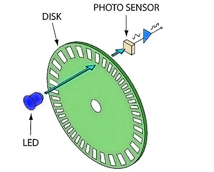
While we could have done that using the internal timer in counter mode to count the pulses over fixed time intervals to detect the motor’s RPM speed without even using interrupts at all. And there are so many other applications that can be accelerated using internal hardware peripherals without completely relying on interrupts. Especially when it’s going to generate high-frequency interrupt signals that would unnecessarily load the CPU.
Parts List
Here is the full components list for all parts that you’d need in order to perform the practical LABs mentioned here in this article and for the whole Arduino Programming series of tutorials found here on DeepBlueMbedded. Please, note that those are affiliate links and we’ll receive a small commission on your purchase at no additional cost to you, and it’d definitely support our work.
Download Attachments
You can download all attachment files for this Article/Tutorial (project files, schematics, code, etc..) using the link below. Please consider supporting my work through the various support options listed in the link down below. Every small donation helps to keep this website up and running and ultimately supports our community.
Arduino Interrupts Wrap Up
To conclude this tutorial, we’d like to highlight the fact that the Arduino interrupts are very useful in so many applications in which you need your Arduino to immediately respond to various events as soon as they arrive. And it needs careful implementation for the ISR handler functions to keep it as efficient as possible. While, sometimes, you may need to avoid using interrupts in the first place.
This tutorial is a fundamental part of our Arduino Series of Tutorials because we’ll build on top of it to interface various sensors and modules with Arduino in other tutorials & projects. So make sure you get the hang of it and try all provided code examples & simulations (if you don’t have your Arduino Kit already).
If you’re just getting started with Arduino, you need to check out the Arduino Getting Started [Ultimate Guide] here.
This is the ultimate guide for getting started with Arduino for beginners. It’ll help you learn the Arduino fundamentals for Hardware & Software and understand the basics required to accelerate your learning journey with Arduino Programming.
This article will give more in-depth information about Arduino External Interrupts, External Interrupt Pins (IRQ Pins), and how to properly configure interrupt pins & write ISR handlers for them.
