In this article, I’ll show you an STM32 DSP Audio Processing & Synthesis PCB design project. I’ll explain some of the design decisions I’ve made while creating this STM32 mixed-signal hardware design, how to prepare the files needed for manufacturing, and how to place the PCBA order at ALLPCB, which is kindly sponsoring this project.
We’ll also develop some firmware in C using STM32Cube IDE to bring up our board and do some cool audio experiments, like: STM32 DDS, MIDI Piano, and WAV Player (SD Card). Without further ado, let’s get right into it!
This Project is Sponsored By ALLPCB
Table of Contents
- STM32 Audio Processing & Synth (Project Overview)
- STM32 DSP Audio Processing & Synth (Hardware HLD)
- STM32 DSP Audio Processing System Hardware Design
- Placing PCBA Order @ ALLPCB
- STM32 DeepSynth Hardware/Firmware Bring-Up
- STM32 GPIO Test (LED Blinking)
- STM32 ST7735 OLED Display Demo Example
- STM32 DAC + DDS Demo Example
- Project1: Manual DDS Tone Player
- STM32 MIDI Input (Rx) Demo Example
- Project2: STM32 DDS Piano MIDI Player
- Extra Firmware Features For The MIDI Piano Project
- Demo Project3: STM32 WAV Player (SD Card)
- Wrap Up
- [YouTube Video] STM32 Audio DSP & Synth PCB Project
STM32 Audio Processing & Synth (Project Overview)
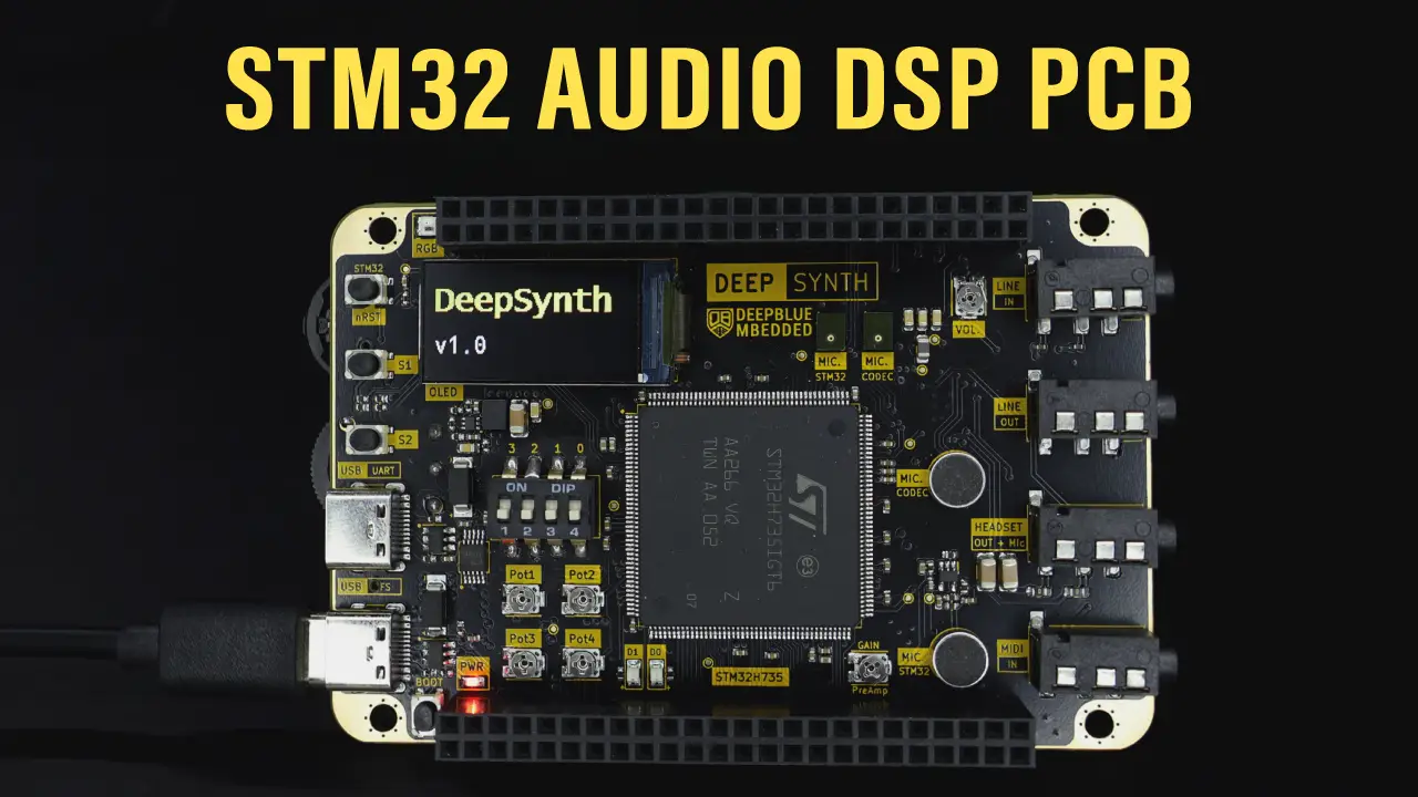
This STM32 mixed-signal hardware design project is intended to be an all-in-one STM32 Audio Synthesis & DSP Processing System with everything we might ever need to develop and experiment with a wide range of audio processing applications on an STM32 target microcontroller.
At the core of this audio processing system, there is a powerful STM32H7 microcontroller (Cortex-M7 @ 550MHz). Supported by a nice set of analog/digital sub-systems, including: Ti Audio Codec, MIDI input interface, 3W Audio power amplifier, OLED display, and much more. Below is a complete list of the hardware features of this PCB project.
STM32 DeepSynth Hardware Features
This is a brief list of the major features of this hardware design project:
- STM32H7 (Cortex-M7 CPU @ 550MHz)
- 2x USB (FS & UART CH340E)
- Audio Codec (TLV320AIC3204)
- Audio Line IN & OUT (TRS)
- Headphone + Mic IN (TRS)
- MIDI IN (TRS + A/B Switch)
- 2x MEMS Microphones
- 2x ECM Microphones
- 3W Audio Power Amplifier
- Speaker OUT Pins
- SD Card Slot (SDIO)
- 0.96″ OLED Display
- 4x Pots + 4x DIP SW + 2x BTNs + 2x LEDs 1x RGB (WS2812)
- Rotary Potentiometer + Thumbwheel
- 64MB QSPI FLASH
- 67x IO Pins
STM32 DeepSynth v1.0 PCB
This is a 3D rendered view of the complete board design (in KiCAD).
 in KiCAD")
STM32 DSP Audio Processing & Synth (Hardware HLD)
After defining the requirements of this STM32 audio processing system, I had to work on designing it at a system level. The output of that stage is typically a diagram that looks like the one shown below. Preliminary parts selection and interface definition should also be done at this stage. This is pretty obvious if you take a deeper look at the HLD (high-level design) diagram below.
After completing the HLD, we’ll group the system components into larger sub-systems, go to KiCAD, and make hierarchical sheets for all of these sub-systems. Then we can start the schematic capture/design stage.
")
STM32 DSP Audio Processing System Hardware Design
This is the hierarchical top-level schematic sheet, showing the major parts of the whole system. Each sub-system has its own schematic sheet file to keep things reasonably manageable.
There are two USB ports for communication and power input, a power supply section for all analog/digital power supply rails, an STM32H735 MCU circuitry, an audio section, and onboard IO devices/ports.
")
1. DC PWR In + USB
There are two USB-C ports that I’m using for power input (+5V) as well as USB for the STM32H735 microcontroller. The other USB port is connected to a USB-UART bridge (CH340E).
2. Power Supplies (Voltage Regulators)
There are multiple analog/digital power supplies and an analog voltage reference on this board. They’re as follows:
- +3V3 Digital (DC/DC Buck Converter)
- +3V3 Analog (LDO Regulator)
- +3V3 VREF (Band-Gap Analog Ref.)
- +5VA (Audio Analog Power Rail)
3. Audio Section
The audio section of this hardware design project includes: the audio codec, MIDI IN interface with type A/B switch, audio power amplifier, ECMs (electret condenser microphones), MEMS microphones, and 4x 3.5mm TRS jack sockets for [MIDI IN, LINE IN, LINE OUT, Headset+Mic].
Audio Codec (TLV320AIC3204)
I’ve selected Ti’s TLV320AIC3204 audio codec for this audio processing system’s PCB project. Since it’s got everything we need in order to achieve the desired set of audio inputs/outputs. Below is the typical application schematic for this audio codec chip.
")
I’ve used the exact same setup with a few minor changes. My audio codec setup goes like this:
- Codec IN1: Line IN
- Codec IN2: ECM Mic
- Codec IN3_R: Headset Mic input
- Codec IN3_L: not used
- Codec HP_RL: Headset speaker out
- Codec LO: Line OUT
- Codec GPIO: MEMS Mic
Below is the internal architecture block diagram of the audio codec that highlights the features (interfaces) we’re using in this project.

MIDI IN (Rx)
There is a single MIDI IN port on this audio processing system’s PCB project. It’s supposed to receive and interpret MIDI messages coming from any MIDI device over a MIDI TRS port that supports (type A & B) standards.
For the MIDI IN schematic design, I’ve followed the MIDI.org Specs (standard specs) for the hardware design of the MIDI interface. They’ve got a very detailed documentation for all MIDI standard versions and hardware specs (for all MIDI ports: IN, OUT, Through).
Below is a screenshot of the MIDI DIN-5 hardware design recommendations by the MIDI Association.
")
Note that other MIDI transports (like TRS that I’ve used) will have slightly different recommendations, so you’d typically need to check out the relevant documentation according to the hardware’s physical MIDI transport that you’re using.
For my case, the MIDI TRS hardware doesn’t have any major deviations from a standard MIDI DIN-5 port, except for the fact that TRS jacks are typically used with standard aux audio cables that are not twisted pairs and usually individually shielded. This is, of course, against the standards recommendations, but we can get away with doing that for experimental lab-based settings, not for an end-user product or something.
ECMs (Electret Condenser Microphones)
There are two ECM microphones on this audio processing system’s PCB project. One is connected to the audio codec’s built-in analog mic interface + bias circuitry. The other ECM microphone is going to a custom analog circuitry (preAmp) whose output is then fed to a single-ended ADC input of the STM32 microcontroller.
The ECM preAmp circuitry is based on: MAX4466

For this to be compatible with the STM32’s ADC reference voltage level, I’ve powered it up using the (+3V3A) analog supply rail. For gain control, I’ve replaced the 100k feedback resistor with an SMD potentiometer.
MEMS Microphones
There are two MEMS microphones on this audio processing system’s PCB project. One is connected to the audio codec’s built-in MEMS microphone input interface, and the other is connected to the STM32H7 microcontroller’s SAI (serial audio interface). So we can experiment with sampling a MEMS microphone either directly from the STM32’s SAI interface or through the audio codec’s built-in digital mic interface.
The MEMS microphone used is: MP34DT05
MEMS Mic1 → Audio Codec

MEMS Mic2 → STM32 SAI Interface

Audio Power Amplifier
One of the most important functional requirements for this project is to have an audio power amplifier capable of driving speakers up to (2~3W). To achieve this, we need a special type of audio amplifier since we’re creating a USB-powered device (VUSB is typically 5V).
I’ve already explained why it’s challenging to produce that much audio output power from a VUSB source. In a previous project, I’ve gone through a low-power audio power amplifier and how it uses BTL to solve this problem and provide amazing output power from a very limited (low-voltage) power supply.
The audio power amplifier used is: Ti’s LM4871
This is a 3W/5V Audio power amplifier chip, capable of delivering up to 2.5W into a 4Ω load with a less than 1% THD.

4. STM32H7 MCU Circuitry
The STM32H735 pin mapping was done using the STM32CubeMX code configurator, and it’s exactly what I’ve used to connect the IO pins to various onboard sub-systems. An external 25MHz crystal oscillator is used as an HSI source.
This target STM32 MCU has a built-in SMPS that I didn’t use, and this is well-documented in the application notes. Other than that, it was really straightforward to connect everything to the target microcontroller and add the bypassing capacitors for power pins and such.
The serial wire debug lines are connected to the IO headers, and the (BOOT0 + NRST) lines are controlled by two onboard push buttons.
5. IOs + OnBoard Peripherals
Below are the onboard IO devices & peripherals that are connected to the STM32H735 microcontroller:
- 2x Buttons (Reset, Boot)
- 2x User LEDs (PWM)
- 2x User Buttons
- 1x OLED 0.96″ Display
- 4x SMD Potentiometers
- 4x DIP Switches
- 1x Rotary Potentiometer
- 1x Thumbwheel
- 1x Neopixel RGB LED (WS2812)
- SD Card Slot (SDIO)
- 0.96″ OLED Display
- 64MB QSPI FLASH
- 67x IO Pins (Headers)
6. Remarks on The PCB Stackup, Layout & Routing
This is a 6-layer PCB, and I’ve decided to use the following stackup (from top to bottom):
[ Sig – GND – Power – Sig – GND – Sig ]
It could have been squeezed down to 4 layers, and in that case, we won’t have many options, as we’ll have to use the following stackup:
[ Sig – GND – GND – Sig] + Routed Power Planes
But using 6 layers gave me the luxury of having a dedicated power layer while having GND shielding for the top & bottom signal layers.
To keep the digital noise away from the analog section, I’ve moved all analog circuitry to the right-hand side third of the entire PCB. All digital ports and peripherals are located on the left side, which is why it may look a bit crowded on that side of the board. But it’s still easy to access and use with no issues.
Placing PCBA Order @ ALLPCB
For this PCB project, I’ve decided to use ALLPCB service for PCBA (PCB Fabrication + Assembly). They also have an electronic components sourcing team of engineers to help you get the best quote price for your project. They can also help you find alternative parts in case something is not stocked anywhere. I’ve selected all the parts needed in my PCB design BOM (bill of materials) using China-based supplies (mainly LCSC).
1) Register for a new account using this link, you’ll get a 30$ discount for your first order + 30$ off the shipping cost as well.
2) You can also join ALLPCB’s referral program through this link to get the following discount coupons:
- 1 friend: $30 coupon
- 3 friends: $50 coupon
- 5 friends: $100 coupon
- 10+ friends: $200 coupon
Each user can receive up to $380 in discount coupons.
1. Upload Your Gerber File & Check PCB Fab. Options
The next step is to upload our PCB Gerber files and modify the PCB fabrication options as needed in the project.

Enable the PCB assembly (1 side or 2 sides). In my project’s case, I’ve chosen the 2-sided assembly.
2. Upload BOM & CPL Files
The next step is to upload your design’s BOM file and the components positions file (CPL) to ALLPCB and let them check the files and they’ll get bakc to you with a quote within 1-2 working days normally.
Check everything in the quote BOM file and make sure the components are selected correctly. Then, you’re good to go and place your order.
3. Pay To Place Your Order
The last step to place your order is to pay for the invoice, and you can apply any valid discount coupon at this step to reduce the cost.
4. Wait For Delivery & Get Ready For Testing!
Here is how it looked after receiving my boards.
I’ll have to manually assemble/mount some parts shown below:
 - Post Manufacturing")
STM32 DeepSynth Hardware/Firmware Bring-Up
Here is how it turned out at the end, with everything mounted and ready for testing!
 Fully-Assembled PCB")
I gave it a quick inspection under the microscope with a “Fine Needle” DMM probe to check for any critical short circuits and also the continuity of critical power paths (VCC, VCCA, VREF, etc).
Everything looks perfect to me at this point. So, the next step is to power the board from my “Current Limited” power supply (+5V/50mA). Just in case anything goes wrong, it won’t push enough current to cause serious damage. Thankfully, it worked like a charm while drawing a few milli-amps.
Here are the actual power supplies’ measurements:
 Power Supplies")
Just note that the audio analog power supply (+5VA) is taken directly from the USB bus voltage after the barrier diode, so it’s normal to expect anywhere (4.5~4.8V) on that analog power rail.
At that point, I was confident enough to plug in the USB cable and start doing some real work!
STM32 GPIO Test (LED Blinking)
This is the first “STM32 life test” example project in which we’ll blink the onboard two LEDs alternatively.
Using STM32CubeIDE, I’ll create a new project and use the example test code below. The exact project creation steps are demonstrated in detail in this tutorial: STM32 GPIO Tutorial (LED Blinking)
LED Blinking GPIO Example Code
The Application Code For This Example (main.c)
/*
 * LAB Name: STM32H7 GPIO Test
 * Author: Khaled Magdy
 * For More Info Visit: www.DeepBlueMbedded.com
*/
int main(void)
{
  MPU_Config();
  HAL_Init();
  SystemClock_Config();
  MX_GPIO_Init();

  while (1)
  {
    HAL_GPIO_WritePin(GPIOB, GPIO_PIN_14, GPIO_PIN_SET);
    HAL_GPIO_WritePin(GPIOB, GPIO_PIN_15, GPIO_PIN_RESET);
    HAL_Delay(250);
    HAL_GPIO_WritePin(GPIOB, GPIO_PIN_15, GPIO_PIN_SET);
    HAL_GPIO_WritePin(GPIOB, GPIO_PIN_14, GPIO_PIN_RESET);
    HAL_Delay(250);
  }
}
Then, we’ll compile & flash the firmware to the board.
LED Blinking Test Result
STM32 ST7735 OLED Display Demo Example
Next up, we’ll test the onboard ST7735 OLED display with the STM32 microcontroller communicating over an SPI bus (at 35Mbps).
In this demo example, I just initialize the OLED display, then show my logo image, and write some text on the display with different font sizes and colors. Just to see if everything is working as expected or not.
STM32 ST7735 OLED Display Demo Result
STM32 DAC + DDS Demo Example
In this demo example, I’ve implemented a DDS unit to generate a controllable-frequency sinusoidal waveform, and we’ll check the output waveform directly from the STM32’s DAC (internally buffered).
I’ll set the output sine wave frequency to 261.63Hz (C4 Note = Middle C) in firmware, and I’ll check the output waveform with my oscilloscope to see the result.
DDS (Direct Digital Synthesis)
DDS (Direct Digital Synthesis) is a digital technique to generate arbitrary analog waveforms (like sine waves) using a reference clock source and can be easily realized (implemented) on microcontroller-based embedded systems for various applications.
It can be as simple or as complex as you’d like it to be. But for sinusoidal audio signal generation (0-20kHz), it can be easily implemented on a microcontroller with a timer interrupt and a couple of simple arithmetic operations.
 - Block Diagram")
I’ll revisit this topic separately to make sure it’s well-covered, as it should be. But for today’s project demo, let’s just say that this technique will help us generate very accurate variable-frequency sinusoidal waveforms with output directly taken from the STM32 microcontroller’s DAC.
STM32 DDS + DAC Output Demo Result
As you can see in the screenshot below, the output waveform is exactly as expected in terms of amplitude & frequency.

Project1: Manual DDS Tone Player
Now, let’s put everything we’ve done so far together and make a bit more complete project.
In this project, we’ll use the thumbwheel to scroll through different notes. The OLED display will show the info of the currently selected note and its status (ON or OFF). The STM32 will have a DDS unit generating a sinusoidal waveform according to the selected note frequency. The output signal from the DAC will go to the onboard audio power amplifier to drive a 4Ω/3W speaker.
STM32 Manual DDS Tone Player Demo Video
Below is the testing demo video for this example project.
STM32 MIDI Input (Rx) Demo Example
One of the most interesting aspects of this audio processing system is its ability to receive and interpret MIDI messages coming from any MIDI controller device. In this demo example, we’ll do a quick and simple bring-up for the MIDI IN feature.
I’ll configure the STM32 UART module to operate @31.25kbps baud rate to receive the incoming MIDI signals from my MIDI keyboard. To make things manageable, we’ll only respond to the following 2 MIDI commands:
- Note ON
- Note OFF
Just to prove that everything is working as expected. More commands can be interpreted and handled later on in future updates.
MIDI Messages Format
A MIDI message is 3 bytes in length, which takes the following format:

Below is a snapshot of the MIDI messages table that lists all MIDI messages (status bytes).

As I’ve stated earlier, in this demo project example, my STM32 firmware will only respond to “Note ON & OFF” MIDI commands and discard any other message. We can refer to the MIDI standard specs for the complete list of MIDI commands for future updates of our firmware project.
STM32 MIDI IN Demo Video
Below is the demo video for this example project.
Project2: STM32 DDS Piano MIDI Player
Now, let’s put everything we’ve done so far into a bit more interesting project. In which we’ll receive MIDI messages coming from my MIDI keyboard and generate the corresponding notes with DDS and send the DAC’s output to the onboard audio power amplifier to drive a 4Ω/3W speaker.
This is a preliminary implementation for a MIDI digital piano synth that can be upgraded later on, bit by bit. But for the sake of showing off our STM32 audio synthesis & processing system hardware design, this will be more than enough to demonstrate what it’s capable of doing.
STM32 DDS Piano MIDI Player Demo Video
Here is the demo video for this example project.
Extra Firmware Features For The MIDI Piano Project
At this point, despite the seemingly good results of the previous MIDI piano project, there are many things that need to be addressed to make it better.
We’ll address most of them in greater detail in the future, but for now, let’s just mention a couple of things that are mandatory to make this project at least viable.
1. String Simulation & Amplitude Envelope
A physical “acoustic” piano doesn’t sound like what we’ve just created. Our piano sounded more robotic or artificial, not anywhere near a natural piano sound. Not only that, but it also had some noise near the start and end of each note played.
In this section, we’ll discuss the issues with the digital MIDI piano we’ve previously created. And also go through a bit of the physics/math of an acoustic piano. which will help develop better firmware in the future to make a better-sounding digital piano.
Output Audio Waveform Discontinuities:
Note on/off at an arbitrary position on the sine table causes the output waveform to have discontinuities at both ends (start & stop). This has square wave wideband harmonics that will show up in the frequency spectrum, causing the speaker to (click or pop) every time a note is played.
Acoustic Piano & Strings Physics:
Acoustic pianos generate their natural sound in the soundboard when pressing a note key triggers a hammer that hits the corresponding “damped string”. Vibration on that string can be described by the equations below. The frequency of the resulting sound is a function of the string length (L). Strings for bass notes (on the left-hand side) are much longer, which is why they make low-frequency sound, and the opposite is true for the right-hand side notes.

An acoustic piano’s sound has an exponential rise and exponential fall (decay) characteristic, as shown in the above figure. And it’s also evident by solving the damped string differential equation below and plotting the resulting wave solution.
Damped Wave Equation:
ρ₀ (∂²u/∂t²) + β (∂u/∂t) = T₀ (∂²u/∂x²)
Where:
- ρ₀ is the linear density of the string.
- T₀ is the tension in the string.
- β is the damping coefficient, representing the strength of the damping force.
- ∂u/∂t is the velocity of the string.
The Solution For The Damped Wave Equation
For a string fixed at both ends (boundary conditions u(0, t) = u(L, t) = 0), can be expressed as a Fourier series:
u(x, t) = Σ [Aₙe(-kt)cos(ωₙt) + Bₙe(-kt)sin(ωₙt)]sin(nπx/L)
Where:
- u(x, t) is the displacement of the string at position x and time t.
- Aₙ and Bₙ are constants determined by initial conditions.
- k = β/(2ρ₀) is related to the damping coefficient.
- ωₙ = √(T₀(nπ/L)²/ρ₀ - k²) is the damped angular frequency.
String Displacement Over Time (Plot)
We can plot the wave equation solution using any software tool, and we’ll get something like the one shown in the figure below. By varying the length of the string (L), we’ll have different output frequencies. Other parameters like damping factor, string density, and string tension can also be tweaked for different sound performance

Does this mean we’ll have to solve complex equations in real-time on our microcontroller to achieve a natural piano sound performance?
We could, but we don’t have to. Since there are already a lot of string simulation and approximation models/algorithms to achieve amazing sound performance using very cheap to compute arithmetic operations, as we’ll see in the next section below.
ADSR Envelope
ADSR (Attack-Decay-Sustain-Release) envelope is an approximated model that can be used to generate various sounds that imitate the physics of different instruments by only changing 4 parameters.
We can change the ADSR 4 parameters to get an amplitude envelope that has a fast rise (attack), a bit of sustain level, and steep decay (release). Very close to the string wave solution we’ve previously seen. By multiplying this ADSR envelope by our sine wave output, we’ll have something that sounds almost exactly like an acoustic (physical) piano.

And it’s so obvious that the ADSR envelope is pretty cheap to compute since it’s linear piece-wise regions with no complex exponentials or whatsoever.
2. Polyphony
In music, polyphony is defined as the maximum number of individual notes an instrument can produce or sustain “simultaneously” at any given time.
For a digital piano, we can simply define it as the maximum number of (notes, sounds, or voices) that it can play or sustain simultaneously at any given time. Typically, a digital piano would have (128~256) or more polyphony to support complex layered sound production with a sustain pedal.
Let’s assume we’ve got a 4-polyphonic digital piano as shown below. If we’ve played 4 notes all at once, it’ll produce a complex sound consisting of all frequencies of the 4 notes we’ve played. The moment we play a fifth note, one of the original 4 notes will drop, even if we’re still holding the key to sustain the sound. We’ll just lose it since we can only have up to 4 simultaneous (notes, sounds, or voices) active at the same time.

And of course, the STM32 MIDI piano demo we’ve previously created didn’t have that implemented. So we can call it a monophonic device since it can only play 1 note at a time. Any new note that’s played will immediately kill the previously held note. Therefore, polyphony is one key area that needs investigation for future updates of that demo project.
Demo Project3: STM32 WAV Player (SD Card)
In this demo example project, we’ll create an STM32 WAV Audio Player (From SD Card) and directly route the audio output signal to the onboard power amplifier to drive a 3W speaker, so we can listen to the audio files.
I’ll generate a mono WAV audio file from an MP3 audio sample (@ 44.1kHz sampling frequency), put it on an SD Card, read it with the STM32’s SDIO peripheral, and send the audio samples to the DAC output (@ 44.1kHz) to reproduce the audio.
The OLED display will show the current status of the WAV audio player (Playing or Paused).
WAV Audio File Format
To read WAV audio files, we’ll need to have a look at Microsoft’s WAV audio file (header + data) structure, as shown in the figure below.
")
If we already know everything about the WAV file, since we’ll generate it from Audacity later on, we can just skip the first 44bytes of the WAV file and directly read the audio samples from that point on till the end-of-file.
STM32 WAV Player (SD Card) Firmware
The firmware of this demo project can be explained as follows:
Audio Samples Buffer: I’ve created an audio samples buffer array to hold 1 second worth of audio samples data (44.1k samples).
Timer-Triggered DMA: Timer1 is configured to trigger a DMA channel (@44.1kHz). The DMA on each trigger will transfer one audio sample from the audio samples buffer to the DAC output in “Circular Mode”.
CPU: Will refill the audio samples buffer by reading the WAV file from the SD Card over a 4-bit SDIO interface. This operation is triggered by the DMA_Half_Complete interrupt. Therefore, the DMA will be sending audio samples from one half of the buffer to the output DAC, while the CPU is refilling the next half buffer with audio samples to be played next. And so on, so forth.

Note: the WAV audio samples are “16-bit signed”, while the STM32’s DAC is only 12-bit in resolution. Therefore, the CPU will have to add an offset to convert the audio samples to unsigned, then truncate the least significant 4 bits to match the DAC resolution. This has to happen every time a chunk of data is read; it needs to be processed like that before it’s written to the audio samples buffer array.
Finally, the CPU also handles input control buttons, OLED display update, and such in an interrupt-based way. So it only reacts when a change happens.
Preparing WAV Audio Files
I used Audacity to generate the WAV audio files @ 44.1kHz sampling rate. It’s a great open-source (free) software tool that’s widely used for audio editing/processing. Given that MP3 is the most popular audio file format since it’s ultra compact (encoded compression) compared to the WAV audio file format, we’ll have to use software like Audacity to do the conversion for us.
Since we have only 1 audio power amplifier to drive a single speaker, we expect to play mono audio files. That’s why I’ll generate my WAV files in mono format (16-bit signed audio samples). Stereo audio files can still be read, but they’ll need an extra step in the preprocessing stage done by the CPU to convert audio samples to mono.
STM32 WAV Player (SD Card) Demo Test
Here is a demo video for our STM32 project’s board playing a WAV audio file from an SD Card, through the MCU’s built-in DAC, to the onboard audio power amplifier, and directly to a 4Ω/5W speaker.
Wrap Up
By the end of this project, I hope you’ve found it helpful, inspiring, or at least interesting to follow along with. I’ve got so many things to experiment with using this board, especially the audio codec section after completing its firmware driver. I’ll do my best to document that work and hopefully share some of it on our YouTube Channel, so stay tuned for that.
If you’ve got any questions or would like me to do a specific application using this board, just let me know in the comments. I’ll be glad to hear your take on this!
[YouTube Video] STM32 Audio DSP & Synth PCB Project
More interesting projects are coming soon. Subscribe to our channel to not miss new content releases!
are the files available?