In this tutorial, we’ll discuss The STM32 PWM Input Mode, how to configure and use the PWM input mode in STM32 microcontrollers, and how to measure an input PWM signal’s duty cycle & frequency with code example and a full test project. Without further ado, let’s get right into it!
Table of Contents
- STM32 PWM Input Mode
- STM32 PWM Input Mode (Measure PWM Signal)
- STM32 PWM Input Mode Example Code Project
- Wrap Up
STM32 PWM Input Mode
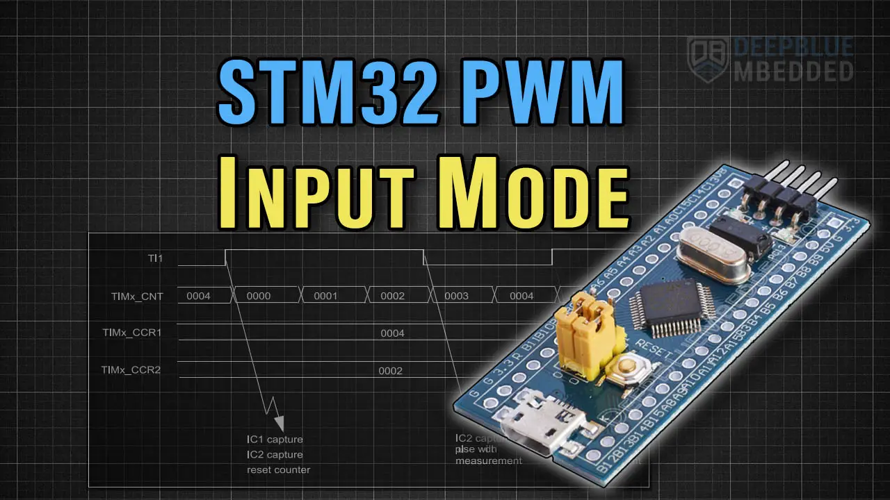
The STM32 PWM Input Mode is a special case of the Timer Input Capture Mode which we’ve discussed in detail in a previous tutorial. It’s also considered one of the Combined Channels Modes in STM32 Timers.
In PWM Input Mode, two input capture units are internally routed together and tied to the same timer input pin. Each input capture unit activates on an opposite edge of the other (IC1-> Rising & IC2->Falling, or the opposite).
This setup is very useful for measuring a PWM incoming signal and calculating its duty cycle and period (1/Frequency).

The counter is reset on each rising edge of the incoming PWM signal, therefore it’s hard to use the same timer for other purposes as it’s not free-running, unlike in input capture mode.
STM32 PWM Input Mode (Measure PWM Signal)
To Measure a PWM input signal’s period (1/Frequency) and duty cycle, we can use the PWM input mode with the following configurations.
#1
Open STM32CubeMX, create a new project, and select the target microcontroller. For me, it’s (STM32F103C8T6 / BluePill)
#2
I’ve selected Timer2 and enabled the combined channels feature (PWM Input). The physical pin of the timer input is, therefore, TIM2_CH1 (PA0).

#3
We need also to enable the timer2 interrupts from the NVIC configurations tab.
")
#4
Go to the Clock configuration page and select a clock source to give you the maximum SysClk of 72MHz (in my case). The higher the clock rate, the easier it is to measure high-frequency PWM input signals.

#5
Name & Generate The Project Initialization Code For CubeIDE or The IDE You’re Using.
The TIM2 configurations can be changed to allow measuring low-frequency PWM input signals by increasing the Prescaler value. The configuration I’m using here has a 0 prescaler which makes it easy to measure high-frequency input signals and impossible to measure low-frequency PWM input signals due to Timer Overflow.
It’s hard to account for timer overflow events while operating in the PWM input mode, unlike the Timer Input Capture Mode.
STM32 PWM Input Mode Example Code Project
Here is The Application Code For This LAB (main.c)
/*
 * LAB Name: STM32 PWM Input (Combined Channels) Mode Example
 * Author: Khaled Magdy
 * For More Info Visit: www.DeepBlueMbedded.com
*/
#include "main.h"

#define F_CLK  72000000UL

TIM_HandleTypeDef htim2;
uint32_t Frequency, CycleTime = 0;
float Duty = 0.0;

void SystemClock_Config(void);
static void MX_GPIO_Init(void);
static void MX_TIM2_Init(void);

int main(void)
{
  HAL_Init();
  SystemClock_Config();
  MX_GPIO_Init();
  MX_TIM2_Init();

  HAL_TIM_IC_Start_IT(&htim2, TIM_CHANNEL_1); // Signal Input Channel (Main)
  HAL_TIM_IC_Start(&htim2, TIM_CHANNEL_2);    // Secondary Channel

  while (1)
  {

  }
}

void HAL_TIM_IC_CaptureCallback(TIM_HandleTypeDef *htim)
{
	if (htim->Instance == TIM2)
	{
		CycleTime = HAL_TIM_ReadCapturedValue(htim, TIM_CHANNEL_1);
		if (CycleTime != 0)
		{
			Duty = (HAL_TIM_ReadCapturedValue(htim, TIM_CHANNEL_2) *100.0)/CycleTime;
			Frequency = (F_CLK/CycleTime);
		}
	}
}
STM32 PWM Input Mode Example Testing
For testing the PWM input mode example project, connect any PWM source generator’s signal to the STM32 TIM2_CH1 pin (PA0). Then start a debugging session with a single break point as indicated in the screenshot below and observe the Duty & Frequency variables in the live expressions debug window.
")
Required Parts For STM32 Examples
All the example Code/LABs/Projects in this STM32 Series of Tutorials are done using the Dev boards & Electronic Parts Below:
| QTY. | Component Name | Amazon.com | AliExpress | eBay |
| 1 | STM32-F103 BluePill Board (ARM Cortex-M3 @ 72MHz) | Amazon | AliExpress | eBay |
| 1 | Nucleo-L432KC (ARM Cortex-M4 @ 80MHz) | Amazon | AliExpress | eBay |
| 1 | ST-Link V2 Debugger | Amazon | AliExpress | eBay |
| 2 | BreadBoard | Amazon | AliExpress | eBay |
| 1 | LEDs Kit | Amazon & Amazon | AliExpress | eBay |
| 1 | Resistors Kit | Amazon & Amazon | AliExpress | eBay |
| 1 | Capacitors Kit | Amazon & Amazon | AliExpress & AliExpress | eBay & eBay |
| 1 | Jumper Wires Pack | Amazon & Amazon | AliExpress & AliExpress | eBay & eBay |
| 1 | Push Buttons | Amazon & Amazon | AliExpress | eBay |
| 1 | Potentiometers | Amazon | AliExpress | eBay |
| 1 | Micro USB Cable | Amazon | AliExpress | eBay |
★ Check The Links Below For The Full Course Kit List & LAB Test Equipment Required For Debugging ★
Download Attachments
You can download all attachment files for this Article/Tutorial (project files, schematics, code, etc..) using the link below. Please consider supporting our work through the various support options listed in the link down below. Every small donation helps to keep this website up and running and ultimately supports the whole community.
Wrap Up
In conclusion, we’ve explored the STM32 PWM Input Mode, how it works, and how to configure the STM32 timer combined channels mode to operate in the PWM input mode to capture and measure any incoming PWM signal’s period & duty cycle.
You can build on top of the provided example code project and integrate it into your system. You can also check the rest of the tutorials in this series to learn more about other features of the STM32 PWM.
")
 Example Code Mode1-2-3")

 Example Code")
 + Example Code")
")
 - Stop PWM Safely")