
In this tutorial, we’ll discuss The STM32 BLDC (Brushless) Motor Control With ESC, and how to configure/use the STM32 PWM to generate the signal needed by the ESC to control the brushless DC (BLDC) motor’s speed/throttle. You’ll also learn how to wire up your STM32 microcontroller’s board with an ESC + BLDC motor, develop some firmware code examples to create a full demo project. Without further ado, let’s get right into it!
Table of Contents
- STM32 Brushless (BLDC) Motor + ESC Fundamentals
- STM32 Brushless (BLDC) Motor Control
- STM32 Brushless (BLDC) Motor Control Example Project
- Wrap Up
STM32 Brushless (BLDC) Motor + ESC Fundamentals
BLDC (Brushless DC) motors are a special type of DC motor that requires 3-phase AC voltage and special control algorithms to achieve proper motor commutation. This is the job of an ESC (Electronic Speed Controller) that handles BLDC motor control and allows us to adjust the motor RPM (speed) using a simple PWM input signal that can be generated by any microcontroller including STM32 MCUs.
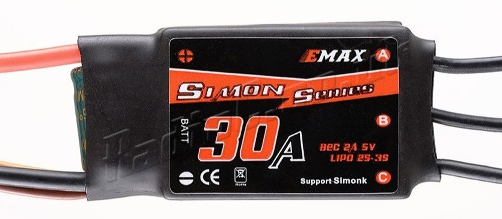
In this tutorial, we’ll interface an STM32 microcontroller with the BLDC Motor & ESC shown below.
 |  |
Brushless (BLDC) Motor KV Rating
This BLDC (Brushless) Motor has a KV rating of 2200 and it can be powered by a 2S-4S LiPo battery (7.4v-14.8v). The ESC has a 30A current ranting, and it should be able to operate at the same voltage range (2S-4S) to be able to achieve the maximum speed (RPM).
The KV rating of a brushless (BLDC) motor defines the RPM of the motor per volt at no load. For my current setup, the BLDC motor I’ve got has a KV of 2200 and the ESC is 2-3S, So the maximum voltage I’ll be able to operate this (BLDC+ESC) at is 3Sx3.7 = (11.1v). Therefore, the maximum achievable RPM = KV x Voltage = 2200 x 11.1 = 24420 RPM.
You can use the calculator tool below to figure out the RPM of your brushless (BLDC) motor given its KV rating and the battery voltage you’re going to use.
KV to RPM Converter
RPM:
STM32 + Brushless (BLDC) Motor & ESC Wiring
It’s so easy to wire up the BLDC motor + ESC with an STM32 microcontroller board. We need a PWM output pin that goes from the STM32 MCU to the ESC, then you should connect the 3-Phase wires of the BLDC motor with the ESC 3-Phase outputs, and provide +5v logic supply to the ESC (from your STM32 dev board). Finally, power up the ESC using a LiPo battery (3S or 4S) or a DC power supply.
Here is the wiring diagram for the example project we’ll implement in this tutorial.
 Motor Control Example Code - Wiring")
If you’re using a DC power supply instead of a LiPo battery, make sure to check its maximum voltage rating (3S, 4S, etc). This is crucial so as not to put it into an over-voltage error state.
The ESC needs a +5v logic supply input as well as a PWM signal. The PWM signal can be 3.3v or 5v logic level, it doesn’t matter that much. What does matter however, is the +5v logic supply. You NEED to connect your STM32 over USB or any DC input voltage so that it can provide a +5v to the ESC logic supply input pin.
Powering up your STM32 through a debugger will only provide 3.3v, but the 5v output pin on your board won’t be effective in that case.
STM32 Brushless (BLDC) Motor Control
There are two main routes when it comes to adding a Brushless (BLDC) motor to your STM32-based system. The first of which, is to design your own ESC board with the target STM32 microcontroller on the same board with all required electronics. The other way is to use a pre-built commercially available ESC module that can handle the voltage/current ratings required to drive your motor.
1. DIY STM32 Custom ESC Board
Obviously, it’s much harder to design your own custom ESC board that includes your target STM32 MCU with all the required electronics (power supplies, protections, 3-phase inverter bridge, MOSFET gate drivers, current/voltage sensing, etc). Not only that, you’ll also have to implement your own firmware motor control algorithm to drive the motor and make sure it’s functioning properly with some safety features (stall detection, OVP, OCP, etc).
This is of course beyond the objectives of this tutorial, but you can find below a detailed design article for my custom STM32 ESC motor control dev board that might give you some inspiration and a sense of what you may need to learn in order to pursue designing your own BLDC/PMSM motor driver board that can support FOC (Field-Oriented Control), Six-Step Commutation For BLDCs, etc.
")
This article will give more in-depth information about designing your custom STM32 ESC board that supports multiple motor control algorithms (i.e. FOC, etc). There is also a 1hr long YouTube video where I go through the design process of that PCB board.
2. Using a Standalone ESC + PWM Control
This is the more feasible solution in most cases, an off-the-shelf ESC module with the required voltage/current ratings to drive your BLDC motor with an easy-to-generate PWM input signal to control the Speed (throttle).
The ESC expects a PWM signal at a 50Hz frequency exactly like a servo motor. The minimum pulse width is 1ms (associated with 0 RPM speed). The maximum pulse width is 2ms (associated with the maximum RPM speed).
 Motor Control ESC")
This setup is what we’ll use in the STM32 BLDC Motor control example project of this tutorial hereafter in the following section. I’ve shown you the wiring diagram earlier, so let’s now get to the firmware code!
Buy A Brushless (BLDC) Motor Here: (Amazon – AliExpress – eBay)
Buy An ESC Driver Module Here: (Amazon – AliExpress – eBay)
STM32 Brushless (BLDC) Motor Control Example Project
In this example project, we’ll configure our STM32 microcontroller’s Timer1 to enable the PWM output on CH1. We’ll set the PWM output signal’s frequency to 50Hz which is required by the ESC module.
We’ll use a potentiometer with an ADC channel to read its value and use it to control the BLDC motor speed. By varying the PWM duty cycle, we can achieve a 1ms pulse (for 0 RPM) by setting the duty cycle to nearly 5% (1m/(1/50Hz)). By doing the same, we’ll get a 2ms pulse (for Max RPM) by setting the duty cycle to 10%.
To find out the digital values that correspond to those duty cycle values and configure your PWM’s frequency, you can find this STM32 PWM Calculator Tool to make it easier for you to set it up.
For My BluePill STM32 running @ 72MHz, The ARR & Prescaler values needed to generate a 50Hz PWM signal are as follows:
- ARR = 65453
- PSC = 21
- 5% Duty = 3273
- 10% Duty = 6545
Finally, we need to map the potentiometer’s ADC readings which have the following range (0 up to 4095) to the 5%-10% duty cycle range (3273 to 6545). This makes the full rotation range of the potentiometer match the full speed control range (1ms up to 2ms pulse).
#1
Open STM32CubeMX, create a new project, and select the target microcontroller. For me, it’s (STM32F103C8T6 / BluePill)
#2
Configure the timer (TIM1) as follows to enable the PWM output on CH1.

#3
Enable ADC CH0 analog input.
#4
Go to the Clock configuration page and select a clock source to give you the maximum SysClk of 72MHz (in my case).

#5
Name & Generate The Project Initialization Code For CubeIDE or The IDE You’re Using.
STM32 Brushless (BLDC) Motor Control Example Code
Here is The Application Code For This LAB (main.c)
/*
 * LAB Name: STM32 BLDC (Brushless) Motor Control With ESC
 * Author: Khaled Magdy
 * For More Info Visit: www.DeepBlueMbedded.com
*/
#include "main.h"

uint32_t AD_RES = 0;

ADC_HandleTypeDef hadc1;
TIM_HandleTypeDef htim1;

void SystemClock_Config(void);
static void MX_GPIO_Init(void);
static void MX_ADC1_Init(void);
static void MX_TIM1_Init(void);

uint32_t MAP(uint32_t au32_IN, uint32_t au32_INmin, uint32_t au32_INmax, uint32_t au32_OUTmin, uint32_t au32_OUTmax)
{
	return ((((au32_IN - au32_INmin)*(au32_OUTmax - au32_OUTmin))/(au32_INmax - au32_INmin)) + au32_OUTmin);
}

int main(void)
{
  HAL_Init();
  SystemClock_Config();
  MX_GPIO_Init();
  MX_ADC1_Init();
  MX_TIM1_Init();
  HAL_TIM_PWM_Start(&htim1, TIM_CHANNEL_1);
  HAL_ADCEx_Calibration_Start(&hadc1);

  while (1)
  {
	  HAL_ADC_Start(&hadc1); // Start ADC Conversion
	  HAL_ADC_PollForConversion(&hadc1, 1); // Poll ADC1 Perihperal & TimeOut = 1mSec
	  AD_RES = HAL_ADC_GetValue(&hadc1); // Read The ADC Conversion Result
	  TIM1->CCR1 = MAP(AD_RES, 0, 4095, 3273, 6545); // Map The ADC Reading To PWM DutyCycle
	  HAL_Delay(1);
  }
}
ESC Calibration For STM32 PWM Output
Before testing your BLDC Motor with an STM32 microcontroller, it’s better to use a function generator or a servo tester to calibrate the pulse width of the ESC module you’re using. This is also referred to as “ESC Calibration“.
You’ll find out that some ESCs have a minimum pulse width in the range (0.9 to 1.2ms) not exactly 1ms! Also for the upper maximum limit, it’ll be around 2ms but not exactly. After getting the exact pulse widths needed for your ESC to work properly, let’s say (Min = 0.9ms, Max = 2.1ms). This corresponds to duty cycles of (0.9/20 = 4.5%, 2.1/20 = 10.5%). Now, head over to my STM32 PWM Calculator Tool, and enter the F_CLK = SysClk, FPWM = 50Hz, Duty = 4.5%, and 10.5%) to get the digital value that corresponds to each duty cycle percentage.
For a SysClk=72MHz, FPWM=50Hz, the duty cycles will be as follows: (4.5% = 2945, 10.5% = 6873). You get the idea! Just plug in the number you’ve got by testing your ESC and tune the numbers in your code accordingly.
STM32 Brushless (BLDC) Motor Control Example Testing
Here is a testing demo for my STM32F103 blue pill board controlling a brushless (BLDC) motor with an ESC module using a potentiometer for speed (throttle) control.
Required Parts For STM32 Examples
All the example Code/LABs/Projects in this STM32 Series of Tutorials are done using the Dev boards & Electronic Parts Below:
| QTY. | Component Name | Amazon.com | AliExpress | eBay |
| 1 | STM32-F103 BluePill Board (ARM Cortex-M3 @ 72MHz) | Amazon | AliExpress | eBay |
| 1 | Nucleo-L432KC (ARM Cortex-M4 @ 80MHz) | Amazon | AliExpress | eBay |
| 1 | ST-Link V2 Debugger | Amazon | AliExpress | eBay |
| 2 | BreadBoard | Amazon | AliExpress | eBay |
| 1 | LEDs Kit | Amazon & Amazon | AliExpress | eBay |
| 1 | Resistors Kit | Amazon & Amazon | AliExpress | eBay |
| 1 | Capacitors Kit | Amazon & Amazon | AliExpress & AliExpress | eBay & eBay |
| 1 | Jumper Wires Pack | Amazon & Amazon | AliExpress & AliExpress | eBay & eBay |
| 1 | Push Buttons | Amazon & Amazon | AliExpress | eBay |
| 1 | Potentiometers | Amazon | AliExpress | eBay |
| 1 | Micro USB Cable | Amazon | AliExpress | eBay |
★ Check The Links Below For The Full Course Kit List & LAB Test Equipment Required For Debugging ★
Download Attachments
You can download all attachment files for this Article/Tutorial (project files, schematics, code, etc..) using the link below. Please consider supporting our work through the various support options listed in the link down below. Every small donation helps to keep this website up and running and ultimately supports the whole community.
Wrap Up
In conclusion, we’ve discussed the STM32 BLDC Brushless Motor Control with an ESC module, how to configure the STM32 timer to generate the PWM signal needed by the ESC to drive the BLDC motor and control its speed.
You can build on top of the provided example code project and integrate it into your system. You can also check the rest of the tutorials in our STM32 Tutorials Series.
Khaled,
Your tutorials are the best I have ever found/used! Your format (lesson plans), English, exactness, and completeness, are at the top.
Keep up your awesome endeavor.
Best regards, Mark
Khaled,
Thank you so much for this work. Thank you for sharing—your tutorials are a goldmine. I have rarely seen tutorials that are so complete, detailed, clear, and concise. One can really feel the passion in what you do. This is exactly how science moves forward—by making it accessible like this.
All I can say is thank you, thank you, and thank you again.
I couldn’t leave without posting a comment.