In this tutorial, we’ll discuss how to implement STM32 1-Wire (One Wire) Protocol Communication using the STM32 UART (Single-Wire / Half-Duplex) Mode. You’ll learn how to use the STM32 UART in Single-Wire mode to interface the DS18B20 Temperature Sensor With STM32 over 1-Wire communication. Without further ado, let’s get right into it!
Table of Contents
- STM32 1-Wire (One Wire) Protocol
- 1-Wire (One Wire) Transaction Elements
- STM32 1-Wire (One Wire) Implementation
- STM32 DS18B20 1-Wire Example Overview
- DS18B20 With STM32 1-Wire (One Wire) – Example
- Wrap Up
STM32 1-Wire (One Wire) Protocol
The 1-Wire protocol was developed by Dallas Semiconductor (now Maxim Integrated). It’s a low-speed, low-power communication protocol used for connecting devices like temperature sensors, memory chips, and other peripherals to a host (master) microcontroller over a single data line.
The 1-Wire protocol allows for power and data to be delivered over a single wire, making it very efficient for some applications with specific wiring constraints.
1-Wire Protocol Features Summary:
- Host (Master) initiated and controlled bus transactions.
- Only one data line is required, and it is easy to implement in hardware & software.
- Low Power Consumption, Ideal for battery-powered applications.
- Multiple 1-Wire devices can be connected to the same bus and addressed individually using unique ROM codes.
- 3-Phase communication sequence: (Reset Sequence, ROM CMD Sequence, and Function CMD Sequence).
- Two Serial Communication Speeds
1-Wire (One Wire) Transaction Elements
The 1-Wire communication protocol has 3-phase transactions. Each 1-Wire transaction has the following 3 sequences (elements):
- Reset Sequence
- COM CMD Sequence
- F-CMD Sequence
The 3 sequences (elements) of a 1-Wire transaction are shown in the figure below. And we’ll discuss each of them in a bit more detail hereafter in this section.

1-Wire Reset Sequence
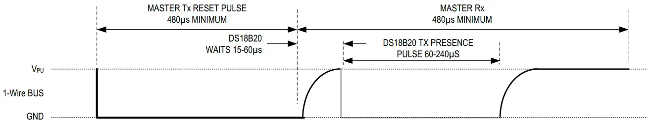
The 1-Wire transaction starts with a reset sequence which is initiated by the host (master) device that pulls the data line low for a minimum of 480µs before releasing it again. This is called the Master Reset Pulse.
If a device on the 1-Wire bus detects the master reset pulse, it’ll respond by pulling the line low for 60-240µs after the host releases the line. This is called the Device Presence Pulse.
1-Wire ROM Command (ROM CMD) Sequence
ROM commands are used to address specific devices on the bus or broadcast commands to all 1-Wire devices. If only one device is connected over the 1-Wire bus, a Skip ROM command can be sent in the (ROM CMD Sequence) to proceed to the function CMD phase.
ROM commands include: (Search ROM, Read ROM, Match ROM, Skip ROM, etc). You need to check the 1-Wire device’s datasheet to know more about the available ROM commands for this specific device.
1-Wire Function Command (F-CMD) Sequence
The Function command (F-CMD) sequence is device-dependent as it’s used to command the 1-Wire device to do specific functions (operations) depending on the device functions listed in the datasheet. Read memory, write memory, read temperature, read humidity, etc.. are all examples of F-CMDs for various 1-Wire devices.
The DS18B20 temperature sensor that we’ll use in this tutorial has an F-CMD called Convert T which is a command to initiate temperature conversion. Another F-CMD that we’ll also use is called Read Scratchpad which is a command to read the DS18B20’s scratchpad memory that contains the temperature conversion result.
STM32 1-Wire (One Wire) Implementation
There are two options to implement a 1-Wire communication protocol with STM32 microcontrollers, which are listed below:
- GPIO Pin
- UART (in Single-Wire Half-Duplex Mode)
And we’ll be using the second method in this tutorial.
There are some challenges for using the standard STM32 UART hardware in single-wire (half-duplex) mode as it’s not “ready” to do 1-wire transactions out of the box. It needs a bit of tuning and real-time configuration change to obey the timing constraints of the 1-Wire communication protocol.
In this tutorial, we’ll use the DS18B20 temperature sensor to test our implementation of STM32 UART-based 1-wire communication. So, let’s first check its datasheet and learn more about its 1-Wire signal timings, commands, etc.
DS18B20 1-Wire Timings
As stated in the DS18B20 datasheet, the timing diagrams for various 1-Wire protocol elements are as follows:
| Master (Host) Write / Read Timings: |
 |
| Reset Sequence Timing: |
 |
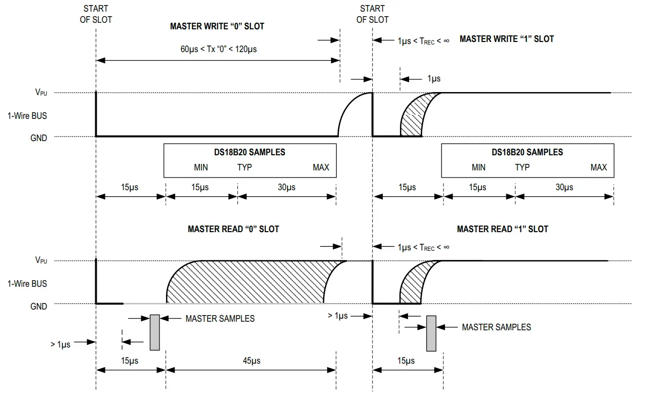
Master Write Bit “1”
According to the DS18B20 datasheet, to send a bit “1,” the data line should transition from HIGH to LOW, stay LOW for approximately 1µs, and then it’s released back to HIGH by the external pull-up resistor. The DS18B20 will sample the data line 15µs after it first goes LOW.
At a baud rate of 115200, each bit period is approximately 8.68µs. The minimum time the MCU can pull the line LOW is a one-bit period, which is around 8.68µs, exceeding the 1µs requirement. However, since the DS18B20 samples the line 15µs after it first goes LOW, we can still mitigate this issue.
By sending the byte 0xFF over UART @ 115200bps:
- The start bit will be LOW for a one-bit period (approximately 8.68µs).
- The following 8 data bits will be HIGH, keeping the line HIGH for the rest of the time.
This ensures that by the time the DS18B20 samples the line (15µs after the initial LOW), the line will be HIGH.
Master Write Bit “0”
According to the DS18B20 datasheet, to send a bit “0,” the data line should transition from HIGH to LOW, stay LOW for at least 60µs, and then it’s released back to HIGH by the pull-up resistor. The DS18B20 will sample the data line 15µs after it first goes LOW.
At a baud rate of 115200, each bit period is approximately 8.68µs. We need the line to stay LOW for at least 60µs, which corresponds to around 7 UART bit periods.
By sending the byte 0x00 over UART @ 115200bps:
- The start bit will be LOW for a one-bit period (approximately 8.68µs).
- The following 8 data bits will also be LOW, keeping the line LOW for the entire byte period.
This will ensure the line is LOW for at least 60µs.
Master Write Byte
To send a byte of data according to the 1-Wire protocol timings in the ds18b20 datasheet using the STM32 UART (single-wire mode) @ 115200bps, we can do it by sending either 0xFF or 0x00 for each bit of the desired data byte as shown in the code snippet below.
|
1 2 3 4 5 6 7 8 9 10 11 12 13 14 |
static void DS18B20_WriteByte(uint8_t data) { uint8_t TxBuffer[8]; for (int i=0; i<8; i++) { if ((data & (1<<i)) != 0){ TxBuffer[i] = 0xFF; } else{ TxBuffer[i] = 0; } } HAL_UART_Transmit(&huart1, TxBuffer, 8, 10); } |
Master Read Bit
According to the DS18B20 datasheet, to read a bit:
- The host/master (STM32 microcontroller) must initiate a LOW pulse on the data line for at least 1µs.
- After this, the line is released, and the sensor will respond by either holding the line LOW (indicating a bit “0”) or allowing it to be pulled HIGH (indicating a bit “1”).
- The master should sample the line approximately 15µs after initiating the LOW pulse.
At a baud rate of 115200, each bit period is about 8.68µs. Therefore, the read-bit operation will go as follows:
- The host sends the byte 0xFF over UART. This sequence ensures that:
- After transmitting the 0xFF, the sensor’s response can be read by capturing the incoming UART RX byte.
- The RX byte’s LSB corresponds to the DS18B20 sensor’s response bit value (1 or 0).
Here is a code snippet for how it’s implemented:
|
1 2 3 4 5 6 7 8 9 10 11 12 |
static uint8_t DS18B20_ReadBit(void) { uint8_t ReadBitCMD = 0xFF; uint8_t RxBit; // Send Read Bit CMD HAL_UART_Transmit(&huart1, &ReadBitCMD, 1, 1); // Receive The Bit HAL_UART_Receive(&huart1, &RxBit, 1, 1); return (RxBit & 0x01); } |
Master Read Byte
This is the same process as the one shown in the previous section of reading a single bit. But it’s done in an 8 times loop to read a whole byte of data.
Here is the code implementation for the read-byte operation:
|
1 2 3 4 5 6 7 8 9 10 11 12 13 |
static uint8_t DS18B20_ReadByte(void) { uint8_t RxByte = 0; for (uint8_t i = 0; i < 8; i++) { RxByte >>= 1; if (DS18B20_ReadBit()) { RxByte |= 0x80; } } return RxByte; } |
Master Reset Sequence (Initialization)
According to the DS18B20 datasheet, the reset sequence consists of:
- Reset Pulse: The master must pull the data line LOW for at least 480µs.
- Presence Pulse: After the reset pulse, the master releases the line (pulls it HIGH), and the slave device responds with a presence pulse by pulling the line LOW for 60-240µs.
This is obviously hard to achieve using the UART’s 115200bps baud rate. Therefore, we’ll change the baud rate down to 9600bps to make it easier for us to achieve the timings of the reset sequence. At this rate, each bit duration is approximately 104µs, which is suitable for generating the required reset pulse duration.
To send a reset pulse, we can send a byte of 0xF0 which has 5 bit periods (1 start bit + 4 bits) at the LOW state. This means the line will be pulled LOW for 5-bit periods (5×10⁴) = 520µs. Which satisfies the requirement of the Reset Pulse (>480µs).
When the DS18B20 device detects the master’s reset pulse, it will send the presence pulse by pulling the line LOW again immediately after the master releases the line. Consequently, the value of the data byte 0xF0 sent by the master will change and this indicates the presence of a DS18B20 device on the 1-Wire bus. Otherwise, if the data 0xF0 remained the same, this means no device was found on the bus.
Here is the code implementation of the 1-Wire reset sequence for the DS18B20 temperature sensor:
|
1 2 3 4 5 6 7 8 9 10 11 12 13 14 15 16 17 |
static uint8_t DS18B20_Init(void) { uint8_t ResetByte = 0xF0, PresenceByte; LL_USART_SetBaudRate(huart1.Instance, HAL_RCC_GetPCLK2Freq(), 9600); // Send reset pulse (0xF0) HAL_UART_Transmit(&huart1, &ResetByte, 1, 1); // Wait for the presence pulse HAL_UART_Receive(&huart1, &PresenceByte, 1, 1); LL_USART_SetBaudRate(huart1.Instance, HAL_RCC_GetPCLK2Freq(), 115200); // Check presence pulse if (PresenceByte != ResetByte){ return 1; // Presence pulse detected } else{ return 0; // No presence pulse detected } } |
DS18B20 1-Wire Commands
The full ROM-CMD & F-CMD command list can be found in the DS18B20’s datasheet but here are the commands we’ll use in this tutorial’s example project.
| CMD Name | CMD Type | CMD Code (Hex) | Command Functionality |
| Skip ROM | ROM-CMD | 0xCC | Skips the ROM command sequence |
| Convert T | F-CMD | 0x44 | Starts a temperature conversion |
| Read Scratchpad | F-CMD | 0xBE | Read the scratchpad memory to get the temperature |
STM32 DS18B20 1-Wire Example Overview
In this example project, we’ll interface the digital temperature sensor DS18B20 with STM32 using UART in single-wire mode to implement the 1-Wire protocol elements according to the DS18B20 datasheet.
We’ll initialize the DS18B20 sensor, read the temperature value every 100ms, and keep repeating.
STM32 DS18B20 Temperature Sensor Wiring Diagram
Here is the wiring diagram for the STM32 DS18B20 (UART Singel-Wire) example project.

DS18B20 With STM32 1-Wire (One Wire) – Example
Step #1
Open STM32CubeMX, create a new project, and select the target microcontroller.
Step #2
Enable UART1 in Single-Wire (Half-Duplex) mode and leave the default configurations as is.

Step #3
Go to the RCC clock configuration page and enable the HSE external crystal oscillator input.

Step #4
Go to the clock configurations page, and select the HSE as a clock source, PLL output, and type in 72MHz for the desired output system frequency. Hit the “ Enter” key, and let the application solve for the required PLL dividers/multipliers to achieve the desired clock rate.

Step #5
Name & Generate The Project Initialization Code For CubeIDE or The IDE You’re Using.
STM32 DS18B20 1-Wire UART Example Code
Here is The Application Code For This LAB (main.c)
|
1 2 3 4 5 6 7 8 9 10 11 12 13 14 15 16 17 18 19 20 21 22 23 24 25 26 27 28 29 30 31 32 33 34 35 36 37 38 39 40 41 42 43 44 45 46 47 48 49 50 51 52 53 54 55 56 57 58 59 60 61 62 63 64 65 66 67 68 69 70 71 72 73 74 75 76 77 78 79 80 81 82 83 84 85 86 87 88 89 90 91 92 93 94 95 96 97 98 99 100 101 102 103 104 105 106 107 108 109 110 111 112 113 114 115 116 117 118 119 120 |
/* * LAB Name: STM32 DS18B20 1-Wire (UART Single-Wire) Example * Author: Khaled Magdy * For More Info Visit: www.DeepBlueMbedded.com */ #include "main.h" #include "stm32f1xx_ll_usart.h" UART_HandleTypeDef huart1; volatile float DS18B20_Temp; void SystemClock_Config(void); static void MX_GPIO_Init(void); static void MX_USART1_UART_Init(void); static uint8_t DS18B20_Init(void); static uint8_t DS18B20_ReadBit(void); static uint8_t DS18B20_ReadByte(void); static void DS18B20_WriteByte(uint8_t); void DS18B20_SampleTemp(void); float DS18B20_ReadTemp(void); int main(void) { HAL_Init(); SystemClock_Config(); MX_GPIO_Init(); MX_USART1_UART_Init(); while (1) { DS18B20_SampleTemp(); // Convert (Sample) Temperature Now DS18B20_Temp = DS18B20_ReadTemp(); // Read The Conversion Result Temperature Value HAL_Delay(100); } } static uint8_t DS18B20_Init(void) { uint8_t ResetByte = 0xF0, PresenceByte; LL_USART_SetBaudRate(huart1.Instance, HAL_RCC_GetPCLK2Freq(), 9600); // Send reset pulse (0xF0) HAL_UART_Transmit(&huart1, &ResetByte, 1, 1); // Wait for the presence pulse HAL_UART_Receive(&huart1, &PresenceByte, 1, 1); LL_USART_SetBaudRate(huart1.Instance, HAL_RCC_GetPCLK2Freq(), 115200); // Check presence pulse if (PresenceByte != ResetByte){ return 1; // Presence pulse detected } else{ return 0; // No presence pulse detected } } static uint8_t DS18B20_ReadBit(void) { uint8_t ReadBitCMD = 0xFF; uint8_t RxBit; // Send Read Bit CMD HAL_UART_Transmit(&huart1, &ReadBitCMD, 1, 1); // Receive The Bit HAL_UART_Receive(&huart1, &RxBit, 1, 1); return (RxBit & 0x01); } static uint8_t DS18B20_ReadByte(void) { uint8_t RxByte = 0; for (uint8_t i = 0; i < 8; i++) { RxByte >>= 1; if (DS18B20_ReadBit()) { RxByte |= 0x80; } } return RxByte; } static void DS18B20_WriteByte(uint8_t data) { uint8_t TxBuffer[8]; for (int i=0; i<8; i++) { if ((data & (1<<i)) != 0){ TxBuffer[i] = 0xFF; } else{ TxBuffer[i] = 0; } } HAL_UART_Transmit(&huart1, TxBuffer, 8, 10); } void DS18B20_SampleTemp(void) { DS18B20_Init(); DS18B20_WriteByte(0xCC); // Skip ROM (ROM-CMD) DS18B20_WriteByte(0x44); // Convert T (F-CMD) } float DS18B20_ReadTemp(void) { uint8_t Temp_LSB, Temp_MSB; uint16_t Temp; float Temperature; DS18B20_Init(); DS18B20_WriteByte(0xCC); // Skip ROM (ROM-CMD) DS18B20_WriteByte(0xBE); // Read Scratchpad (F-CMD) Temp_LSB = DS18B20_ReadByte(); Temp_MSB = DS18B20_ReadByte(); Temp = ((Temp_MSB<<8))|Temp_LSB; Temperature = (float)Temp/16.0; return Temperature; } |
Note That the DS18B20 temperature reading in the scratchpad memory is two-bytes in size containing the 12-bit resolution temperature reading. Dividing the 16-bit reading by 16 (or right-shifting by 4, >>4) gives us the 12-bit temperature value.
STM32 DS18B20 1-Wire UART Example Testing
Here is the testing result of this example project running on my STM32 blue pill (F103C8T6) board. Yes, it’s so hot here right now!

Required Parts For STM32 Examples
All the example Code/LABs/Projects in this STM32 Series of Tutorials are done using the Dev boards & Electronic Parts Below:
| QTY. | Component Name | Amazon.com | AliExpress | eBay |
| 1 | STM32-F103 BluePill Board (ARM Cortex-M3 @ 72MHz) | Amazon | AliExpress | eBay |
| 1 | Nucleo-L432KC (ARM Cortex-M4 @ 80MHz) | Amazon | AliExpress | eBay |
| 1 | ST-Link V2 Debugger | Amazon | AliExpress | eBay |
| 2 | BreadBoard | Amazon | AliExpress | eBay |
| 1 | LEDs Kit | Amazon & Amazon | AliExpress | eBay |
| 1 | Resistors Kit | Amazon & Amazon | AliExpress | eBay |
| 1 | Capacitors Kit | Amazon & Amazon | AliExpress & AliExpress | eBay & eBay |
| 1 | Jumper Wires Pack | Amazon & Amazon | AliExpress & AliExpress | eBay & eBay |
| 1 | Push Buttons | Amazon & Amazon | AliExpress | eBay |
| 1 | Potentiometers | Amazon | AliExpress | eBay |
| 1 | Micro USB Cable | Amazon | AliExpress | eBay |
★ Check The Links Below For The Full Course Kit List & LAB Test Equipment Required For Debugging ★
Download Attachments
You can download all attachment files for this Article/Tutorial (project files, schematics, code, etc..) using the link below. Please consider supporting our work through the various support options listed in the link down below. Every small donation helps to keep this website up and running and ultimately supports the whole community.
Wrap Up
In conclusion, we’ve explored how to set up the STM32 UART in Half-Duplex mode to implement 1-Wire protocol elements according to the DS18B20 temperature sensor’s datasheet. We’ve successfully initialized and sampled temperature data using the DS18B20 with STM32 UART single-wire mode.
You can build on top of the example provided in this tutorial and/or explore the other parts of this STM32 UART tutorial series linked below.

 Rx Tx Examples")


 Protocol + DS18B20 Code Example")
Your post about using STM32 UART for 1-wire interface is the only one on internet with all the necessary details of using the UART drivers (generated by CubeMX) and all the hardware details for using 1-wire for DS18B20 sensor communication. In the past I often used your posts about topics related to STM32 timers.
Your site is among few most useful sites on the web for the Embedded World of microcontrollers. My opinion is biased as we are also using STM32 MCUs and you provide many of their examples and detail explanations . You are also a good teacher – a right collection of necessary topics for an overall understanding of each peripheral, including SW and hardware, is an art in itself.
Thank you very much for your work.
Hi, I don’t see the call to the DS18B20_Init() function, unless I misunderstood something.
Another question is whether the lower layer functions you used to configure the BR UART are provided in the HAL drivers folder when the project is generated by CUBEMX
Regards
Hello Edgardo,
Yes, I didn’t use the init function in the provided example. It’s useful to use it and check the return value to make sure the ds18B20 sensor is present on the 1-wire bus and working properly before starting to use it.
However, it’s totally fine to skip using it and directly read the sensor without any issues.
Regarding your second question, the answer is yes. The low-level (LL) driver functions I’ve used to set the UART’s baud rate to different values is provided in the code generated by CubeMX under drivers/HAL/inc/stm32f1xx_ll_usart.h
All the best,
Khaled M.
Hello,
I’m not sure I understand how the end of the Init function gives a valid result indicating the presence of the device.
As “(PresenceByte != ResetByte)” wold be true if nothing works at all and the UART is simply getting back 0 for all bits (e.g. due to a wiring problem or a fried IC).
If I want to start this project, is it enough to use the STM32 blue pill as that’s all I see wired up in the Fritzing drawing? I don’t see where the Nucleo is used.
It’s absolutely fine to do so. I just tend to use different boards every now and then back when I’ve created these tutorials.
A follow-up to my first post:
Quoting the article: “Consequently, the value of the data byte 0xF0 sent by the master will change and this indicates the presence of a DS18B20 device on the 1-Wire bus. ”
-> But this can only work if, like in the UART-based 1-wire implementation described in an article on analog.com, the TX pin is connected to the RX pin and *full duplex* UART is used, as the sensor modifying the line state _during transmission_ (which works due to the pull-up nature, when the line is currently not dragged down by the master), i.e. this modification of the value needs to be read at the same time as it’s written, which only works if an RX pin is listening in at the same time. While in STM32’s typical USART , it switches between TX and RX on the same pin if half-duplex is being used.
I.e. the presence pulse cannot be correctly detected with the half-duplex / 1 shared TX/RX pin only, setup, and it’s a coincidence that this works for this chip (see my 1st post).
Or did I overlook something somewhere? (I’m trying to implement this with another chip, the TMP1827, where this doesn’t seem to work)
I am using another board with one wire interface, i took results output on Logic Analyzer, which is fine. but when i try to print read/ write values on serial terminal, I either get all 0s or all 1s. what could be possible problem in this case?
Check that RX and TX are enabled within the HAL. You cannot use the enable Rx and enable Tx functions because they do not allow Rx and Tx at the same time.
Hello!
Thank you very much for your interesting tutorial!
The description of the one-wire protocoll and the code snippets were very helpful.
Wish you all the best