| Previous Tutorial | Tutorial 36 | Next Tutorial | |||||
| STM32 Joystick Interfacing Examples & Driver (Library) | |||||||
| STM32 Course Home Page ???? | |||||||
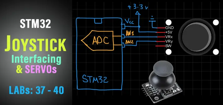
In this tutorial, we’ll be discussing the usage of STM32 ADC and analog input pins to interface and read one joystick or more. I’ll also show you the Joystick library (driver) that I’ve developed for STM32 microcontrollers and discuss how it works and how it’s been built in this way. And we’ll create 4 different example projects with STM32 uC and Joysticks.
We’ll conclude this tutorial with some tests, measurements, and spot the light on potential improvements and features that you can make and add to this driver code. But first of all, we’ll discuss how the Joystick works and the general procedure for reading the Joystick XY positions.
In this tutorial: 4 LABs
| LAB37 | Reading Raw Joystick XY Values & Serial Print Over UART | ||||||
| LAB38 | PWM LED Dimming With Joystick | ||||||
| LAB39 | Servo Motors Control With Joystick | ||||||
| LAB40 | Multiple Joysticks Reading Using Library APIs | ||||||
[toc]
Required Components For LABs
All the example code/LABs/projects in the course are going to be done using those boards below.
- Nucleo32-L432KC (ARM Cortex-M4 @ 80MHz) or (eBay)
- Blue Pill STM32-F103 (ARM Cortex-M3 @ 72MHz) or (eBay)
- ST-Link v2 Debugger or (eBay)
| QTY | Component Name | ???? Amazon.com | ???? eBay.com |
| 2 | BreadBoard | Amazon | eBay |
| 1 | LEDs Kit | Amazon Amazon | eBay |
| 1 | Resistors Kit | Amazon Amazon | eBay |
| 1 | Capacitors Kit | Amazon Amazon | eBay & eBay |
| 2 | Jumper Wires Pack | Amazon Amazon | eBay & eBay |
| 1 | 9v Battery or DC Power Supply | Amazon Amazon Amazon | eBay |
| 1 | Micro USB Cable | Amazon | eBay |
| 1 | Push Buttons | Amazon Amazon | eBay |
| 2 | Joystick Module | Amazon | eBay |
| 1 | USB-TTL Converter or FTDI Chip | Amazon Amazon | eBay eBay |
| 2 | Micro Servo Motor (Metal Gear) |
Amazon | eBay |
★ Check The Full Course Complete Kit List
Some Extremely Useful Test Equipment For Troubleshooting:
- My Digital Storage Oscilloscope (DSO): Siglent SDS1104 (on Amazon.com) (on eBay)
- FeelTech DDS Function Generator: KKMoon FY6900 (on Amazon.com) (on eBay)
- Logic Analyzer (on Amazon.com) (on eBay)
Affiliate Disclosure: When you click on links in this section and make a purchase, this can result in this site earning a commission. Affiliate programs and affiliations include, but are not limited to, the eBay Partner Network (EPN) and Amazon.com.
Joystick Interfacing With STM32
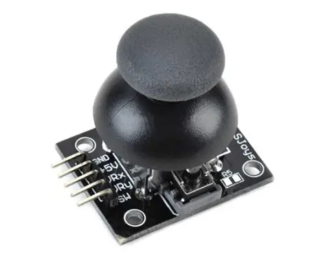
The PS2 joystick module shown in the figure down below is basically a couple of potentiometers (variable resistors) that moves in position while you’re rotating the stick around. This creates a voltage difference that can be read using any microcontroller’s ADC peripheral. The pinout for this module is shown below.
There is something that worth noting here which is the +5v pin. You typically connect this pin to the Vref+ of the ADC in your microcontroller. It’s not always +5 volts, mostly in all Arduinos it is, but in STM32 microcontrollers it’s +3.3v. And of course, in case you’re using any other voltage value for the ADC’s (Vref+) you’ll have to connect this pin to that same voltage level. The ground pin goes to the ground as long as your ADC’s (Vref-) is also grounded.
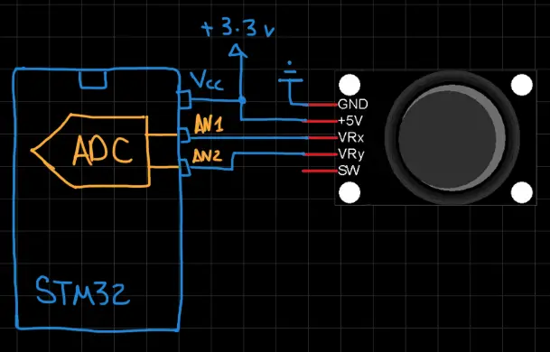
Reading the joystick XY values is a very simple task to do. All you’ve got to do is to read the corresponding ADC channel for each of the 2 analog input pins for X & Y. And that’s all!
The resolution of your ADC determines the full range of values for X & Y positions. For STM32F103 that I’ll be using for testing today, the ADC is 12-Bit in resolution. Therefore, the full range for X & Y values will be [ 0 – 4095 ]. Which you can map to control LED brightness via PWM or servo motor position or whatever, using the MAP function located in the MATH directory on the course’s repo.
STM32 Joystick Driver (Library)
The ECUAL Joystick driver is built for STM32 microcontrollers using ADC’s analog input pins. You’ll have to configure an instance of it and use the APIs to read your Joystick and that’s all. The code should be easily ported to any other STM32 microcontroller or reconfigured to use any AN input pins you want just as we’ll see in this section. And here is a link for the course’s repo, and you’ll find the JOYSTICK driver in the ECUAL directory as usual.
JOYSTICK Driver Code Files
The Joystick driver consists of the following files:
|
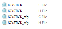 |
You’ll need only to modify the configuration files. The source code for this driver is found in (JOYSTICK.c) and to use it you’ll include the header (JOYSTICK.h). Nothing in the source code needs to be changed at all unless you need to add any extra features or customize the driver for your application’s needs. For today’s labs, we’ll only be changing the configuration files to build some test applications.
Therefore, I’ll write here the code listing for the JOYSTICK.h & JOYSTICK_cfg.c files.
JOYSTICK.h File
|
1 2 3 4 5 6 7 8 9 10 11 12 13 14 15 16 17 18 19 20 21 22 |
#define HAL_ADC_MODULE_ENABLED #include "stm32f1xx_hal.h" // The Number OF JoySticks To Be Used In The Project #define JOYSTICK_UNITS 1 typedef struct { GPIO_TypeDef * JoyStick_xGPIO; GPIO_TypeDef * JoyStick_yGPIO; uint16_t JoyStick_xPIN; uint16_t JoyStick_yPIN; ADC_TypeDef* ADC_Instance; uint32_t ADCx_CH; uint32_t ADCy_CH; }JoyStick_CfgType; /*-----[ Prototypes For All Functions ]-----*/ void JoyStick_Init(uint16_t JoyStick_Instance); void JoyStick_Read(uint16_t JoyStick_Instance, uint16_t* JoyStick_XY); |
If you’re willing to use multiple keypad matrices, just adjust that number definition (JOYSTICK_UNITS).
JOYSTICK Driver APIs
As you’ve seen in the JOYSTICK.h file, the provided APIs do all the basic functionalities that you may need from a Joystick driver library. It initializes the required GPIO analog input pins, the associated ADC, and reads the raw value for X & Y positions at any instance of time.
The structure of the files and the provided APIs look very intuitive and self-explanatory to me. And the example LABs will put everything under test and you’ll see how and when to use each of these functions.
JOYSTICK_cfg.c File
|
1 2 3 4 5 6 7 8 9 10 11 12 13 14 15 |
#include "JOYSTICK.h" const JoyStick_CfgType JoyStick_CfgParam[JOYSTICK_UNITS] = { // JoyStick unit 1 Configurations { GPIOA, GPIOA, GPIO_PIN_6, GPIO_PIN_7, ADC1, ADC_CHANNEL_6, ADC_CHANNEL_7 } }; |
I’ll discuss those configuration parameters in the next section down below.
Available Configurations For ECUAL JOYSTICK Driver
From the code above in JOYSTICK.h & JOYSTICK_cfg.c you can see that there are not many parameters at all in the configuration structure. The config structure will be used to assign the analog input pins to X&Y channels of the joystick, the associated ADC peripheral you’ll be using (it can be ADC1, 2, and so on), and the ADC channel names for the selected analog input pins.
Typical Usage Application Example
Here is a typical usage application for this driver code in order to initialize a Joystick module and read its X channel value and use it to dim an led by writing to the CCR register for PWM duty cycle control.
|
1 2 3 4 5 6 7 8 9 10 11 12 13 14 15 16 17 18 19 20 21 22 23 24 25 26 27 28 29 30 |
#include "main.h" #include "../ECUAL/JOYSTICK/JOYSTICK.h" #define JoyStick1 0 TIM_HandleTypeDef htim2; void SystemClock_Config(void); static void MX_GPIO_Init(void); static void MX_TIM2_Init(void); int main(void) { uint16_t JoyStick1_XY[2] = {0}; HAL_Init(); SystemClock_Config(); MX_GPIO_Init(); MX_TIM2_Init(); JoyStick_Init(JoyStick1); HAL_TIM_PWM_Start(&htim2, TIM_CHANNEL_1); while (1) { JoyStick_Read(JoyStick1, JoyStick1_XY); TIM2->CCR1 = JoyStick1_XY[0]; HAL_Delay(10); } } |
You’ll have to create a local buffer array consisting of 2 uint16_t variables and send it by reference to the function that read in the joystick unit XY values. Even if you’re going to use only one channel X or Y, you still need to read in both of them and use whichever you want. As you might have noticed in the test application code snippet above.
STM32 Joystick Reading & Serial Print – LAB
| LAB Number | 37 |
| LAB Title | STM32 Joystick Reading With Library APIs & UART Serial Print |
- Set up a new project as usual with a system clock @ 72MHz or whatever your uC board supports
- Enable USART1 in CubeMX & Set The BaudRate
- Add the ECUAL / JOYSTICK driver files to our project. As shown here
- Configure 1 Joystick instance in JOYSTICK_cfg.c file
- Initialize the Joystick in the main application, read the Joystick_XY values, convert the digital values to a string, and finally send that string over the UART1 peripheral. And repeat!
And now, let’s build this system step-by-step
Step1: Open CubeMX & Create New Project
Step2: Choose The Target MCU & Double-Click Its Name
STM32F103C8 (the one I’ll be using) or any other STM32 part you’ve got
Step3: Go To The RCC Clock Configuration
Step4: Set The System Clock To Be 72MHz or whatever your uC board supports
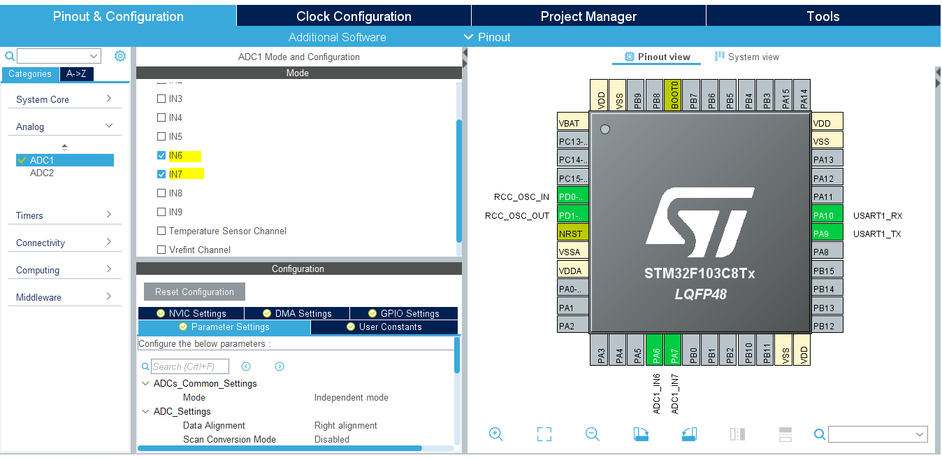
Step5: Enable Any ADC Channel or The 2 You’ll be using For Joystick
We’ll have to do this step just to have the ADC_HAL files added to our project by CubeMX. However, we’ll delete that ADC_Init function and won’t care about ADC operation. Since the Joystick library will handle that. But you’ll just have to enable any ADC channel in CubeMX in order to have the ADC_HAL files added to your project. As the Joystick library depends on them.
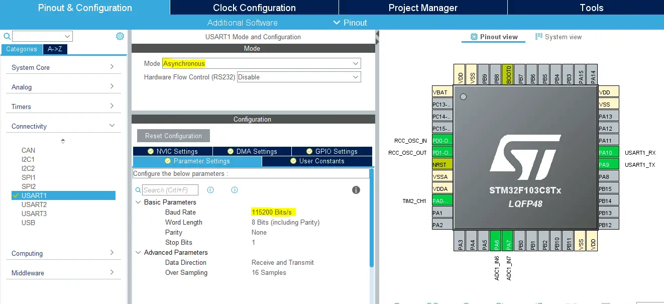
Step6: Enable USART1 & Set The Baud Rate
Step7: Generate The Initialization Code & Open The Project In Your IDE
Step8: Add the ECUAL/ JOYSTICK driver files to your project
Follow This Tutorial which shows you How To Add Any ECUAL Driver To An STM32 Project step-by-step.

Now, we can start developing our application in the main.c source file.
Here is The Application Code For This LAB (main.c)
|
1 2 3 4 5 6 7 8 9 10 11 12 13 14 15 16 17 18 19 20 21 22 23 24 25 26 27 28 29 30 31 32 33 |
#include "main.h" #include "stdio.h" #include "../ECUAL/JOYSTICK/JOYSTICK.h" #define JoyStick1 0 UART_HandleTypeDef huart1; void SystemClock_Config(void); static void MX_GPIO_Init(void); static void MX_USART1_UART_Init(void); int main(void) { uint16_t JoyStick1_XY[2] = {0}; uint8_t MSG[15] = {'\0'}; HAL_Init(); SystemClock_Config(); MX_GPIO_Init(); MX_USART1_UART_Init(); JoyStick_Init(JoyStick1); while (1) { // Read Joystick1 XY Values JoyStick_Read(JoyStick1, JoyStick1_XY); // Print X, Y Values Over UART1 sprintf(MSG, "%d,%d\r\n", JoyStick1_XY[0], JoyStick1_XY[1]); HAL_UART_Transmit(&huart1, MSG, sizeof(MSG), 100); HAL_Delay(10); } } |
Note that: I’ve deleted the auto-generated ADC1 initialization function and its parameter. Since our Joystick library will handle that, we don’t need that function at all.
Download The STM32 Joystick Reading Serial Print LAB37
The Result For This LAB Testing (Video)
STM32 Joystick & PWM LED Dimming – LAB
| LAB Number | 38 |
| LAB Title | STM32 Joystick Reading With Library APIs & PWM LED Dimming |
- Set up a new project as usual with a system clock @ 72MHz or whatever your uC board supports
- Enable Timer2/CH1 PWM in CubeMX & Set The ARR
- Add the ECUAL / JOYSTICK driver files to our project. As shown here
- Configure 1 Joystick instance in JOYSTICK_cfg.c file
- Initialize the Joystick in the main application, read the Joystick_XY values, write the X position value to the Timer2 CCR1 register to control the PWM’s Duty cycle
And now, let’s build this system step-by-step
Step1: Open CubeMX & Create New Project
Step2: Choose The Target MCU & Double-Click Its Name
STM32F103C8 (the one I’ll be using) or any other STM32 part you’ve got
Step3: Go To The RCC Clock Configuration
Step4: Set The System Clock To Be 72MHz or whatever your uC board supports
Step5: Enable Any ADC Channel or The 2 You’ll be using For Joystick
We’ll have to do this step just to have the ADC_HAL files added to our project by CubeMX. However, we’ll delete that ADC_Init function and won’t care about ADC operation. Since the Joystick library will handle that. But you’ll just have to enable any ADC channel in CubeMX in order to have the ADC_HAL files added to your project. As the Joystick library depends on them.
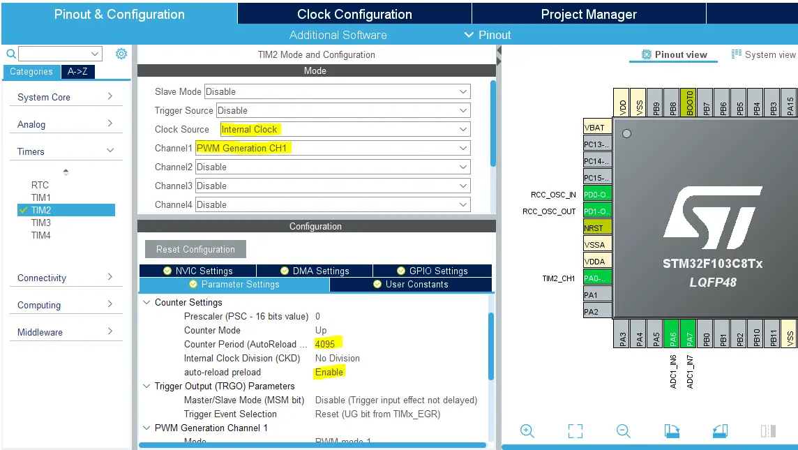
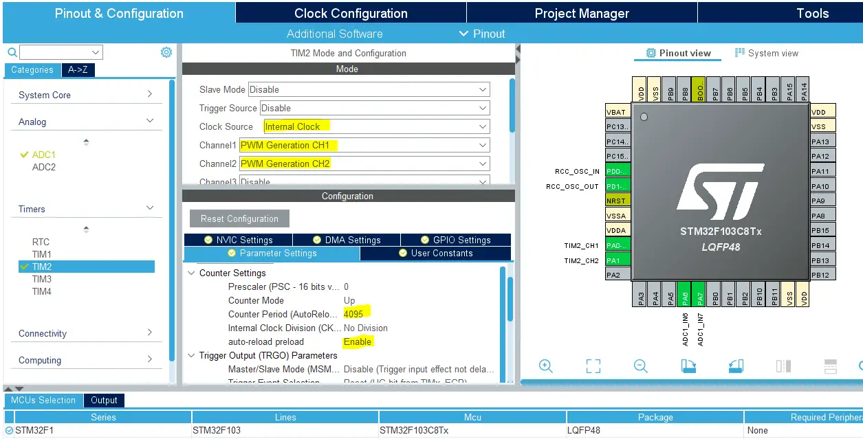
Step6: Enable Timer2/CH1 PWM & Set The ARR Register
Here I’m setting the ARR register value to be 4095 which is the maximum value we’ll be getting from the Joystick reading. Because the ADC1 peripheral in this microcontroller part has a resolution of 12-Bits. By doing this, we won’t need to do any mapping at all. Just move the Joystick X position reading to the Tim2-CCR1 register and you’ll have the PWM duty cycle changed correspondingly.
Step7: Generate The Initialization Code & Open The Project In Your IDE
Step8: Add the ECUAL/ JOYSTICK driver files to your project
Follow This Tutorial which shows you How To Add Any ECUAL Driver To An STM32 Project step-by-step.
Now, we can start developing our application in the main.c source file.
Here is The Application Code For This LAB (main.c)
|
1 2 3 4 5 6 7 8 9 10 11 12 13 14 15 16 17 18 19 20 21 22 23 24 25 26 27 28 29 |
#include "main.h" #include "../ECUAL/JOYSTICK/JOYSTICK.h" #define JoyStick1 0 TIM_HandleTypeDef htim2; void SystemClock_Config(void); static void MX_GPIO_Init(void); static void MX_TIM2_Init(void); int main(void) { uint16_t JoyStick1_XY[2] = {0}; HAL_Init(); SystemClock_Config(); MX_GPIO_Init(); MX_TIM2_Init(); JoyStick_Init(JoyStick1); HAL_TIM_PWM_Start(&htim2, TIM_CHANNEL_1); while (1) { JoyStick_Read(JoyStick1, JoyStick1_XY); TIM2->CCR1 = JoyStick1_XY[0]; HAL_Delay(10); } } |
Note that: I’ve deleted the auto-generated ADC1 initialization function and its parameter. Since our Joystick library will handle that, we don’t need that function at all.
Download The STM32 Joystick PWM LED Dimmer LAB38
The Result For This LAB Testing (Video)
STM32 Joystick & Servo Motors – LAB
| LAB Number | 39 |
| LAB Title | STM32 Joystick Reading & Servo Motors Control |
- Set up a new project as usual with a system clock @ 72MHz or whatever your uC board supports
- Add the ECUAL / JOYSTICK driver files to our project. As shown here
- Add the ECUAL / SERVO driver files to our project
- Add the MATH library files & util files to our project
- Configure 1 Joystick instance in JOYSTICK_cfg.c file
- Configure 2 Servo instance in SERVO_cfg.c file
- Initialize the Joystick & Servo Motors in the main application, read the Joystick_XY values, Map the XY values to Servo motor 1 & 2 ranges.
And now, let’s build this system step-by-step
Step1: Open CubeMX & Create New Project
Step2: Choose The Target MCU & Double-Click Its Name
STM32F103C8 (the one I’ll be using) or any other STM32 part you’ve got
Step3: Go To The RCC Clock Configuration
Step4: Set The System Clock To Be 72MHz or whatever your uC board supports
Step5: Enable Any ADC Channel or The 2 You’ll be using For Joystick
We’ll have to do this step just to have the ADC_HAL files added to our project by CubeMX. However, we’ll delete that ADC_Init function and won’t care about ADC operation. Since the Joystick library will handle that. But you’ll just have to enable any ADC channel in CubeMX in order to have the ADC_HAL files added to your project. As the Joystick library depends on them.
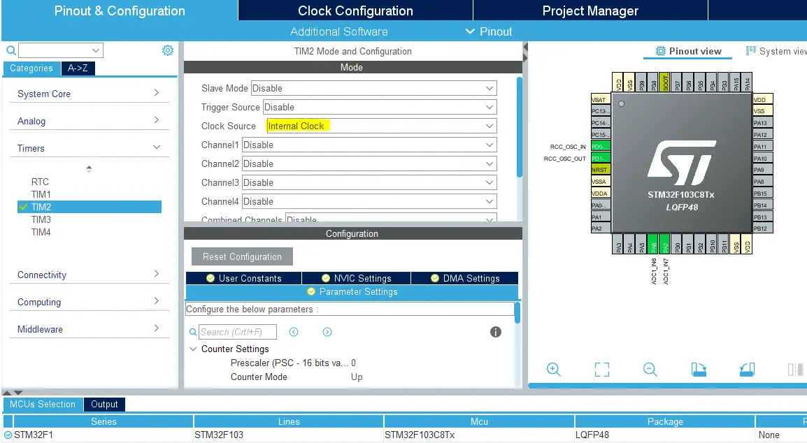
Step6: Enable Any Timer Module or The one You’ll be using For Servo Motors
We’ll have to do this step just to have the TIMER_HAL files added to our project by CubeMX. However, we’ll delete that Timer2_Init function and won’t care about TIMER PWM operation. Since the Servo library will handle that. But you’ll just have to enable any Timer Module in CubeMX in order to have the TIMER_HAL files added to your project. As the Servo library depends on them.
Step7: Generate The Initialization Code & Open The Project In Your IDE
Step8: Add the ECUAL/ JOYSTICK driver files to your project
Step9: Add the ECUAL/ SERVO driver files to your project
Follow This Tutorial which shows you How To Add Any ECUAL Driver To An STM32 Project step-by-step.
Step10: Add the MATH files & util
Now, we can start developing our application in the main.c source file.
Here is The Application Code For This LAB (main.c)
|
1 2 3 4 5 6 7 8 9 10 11 12 13 14 15 16 17 18 19 20 21 22 23 24 25 26 27 28 29 30 31 32 33 34 35 36 37 38 39 40 41 |
#include "main.h" #include "../MATH/MATH.h" #include "../ECUAL/JOYSTICK/JOYSTICK.h" #include "../ECUAL/SERVO/SERVO.h" #define JoyStick1 0 #define ServoMotor1 0 #define ServoMotor2 1 void SystemClock_Config(void); static void MX_GPIO_Init(void); int main(void) { uint16_t JoyStick_XY[2] = {0}; uint16_t Servo1Pulse = 0, Servo2Pulse = 0; uint16_t Servo1MaxPulse = 0, Servo1MinPulse = 0; uint16_t Servo2MaxPulse = 0, Servo2MinPulse = 0; HAL_Init(); SystemClock_Config(); MX_GPIO_Init(); JoyStick_Init(JoyStick1); SERVO_Init(ServoMotor1); SERVO_Init(ServoMotor2); Servo1MinPulse = SERVO_Get_MinPulse(ServoMotor1); Servo1MaxPulse = SERVO_Get_MaxPulse(ServoMotor1); Servo2MinPulse = SERVO_Get_MinPulse(ServoMotor2); Servo2MaxPulse = SERVO_Get_MaxPulse(ServoMotor2); while (1) { JoyStick_Read(JoyStick1, JoyStick_XY); Servo1Pulse = MAP(JoyStick_XY[0], 0, 4095, Servo1MinPulse, Servo1MaxPulse); Servo2Pulse = MAP(JoyStick_XY[1], 0, 4095, Servo2MinPulse, Servo2MaxPulse); SERVO_RawMove(ServoMotor1, Servo1Pulse); SERVO_RawMove(ServoMotor2, Servo2Pulse); HAL_Delay(10); } } |
Note that: I’ve deleted the auto-generated ADC1 initialization function and its parameter. Since our Joystick library will handle that, we don’t need that function at all. And it’s the same case for the Timer2 function as well.
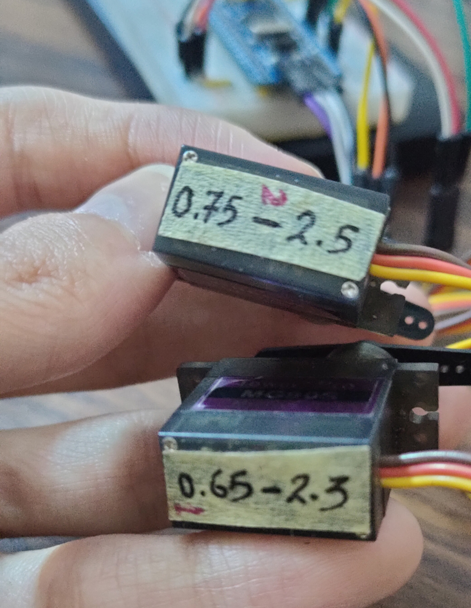
Note also: I did firstly read the min & max pulse count for each servo motor just to define the full range of motion for each one of them. This will step is required to make the mapping process as accurate as possible. You can refer to my old article about servo motors to know more about the min & max pulse and how I did come up with these values. As you’ll notice in SERVO_cfg.c file, the defined min & max pulse widths are slightly different for motor 1 & 2.
Download The STM32 Joystick Servo Motors Control LAB39
The Result For This LAB Testing (Video)
STM32 Multiple Joysticks Reading – LAB
| LAB Number | 40 |
| LAB Title | STM32 Multiple Joystick Reading With Library APIs & PWM LEDs Dimming |
- Set up a new project as usual with a system clock @ 72MHz or whatever your uC board supports
- Enable Timer2/CH1 & CH2 PWM in CubeMX & Set The ARR
- Add the ECUAL / JOYSTICK driver files to our project. As shown here
- Configure 1 Joystick instance in JOYSTICK_cfg.c file
- Initialize the Joystick in the main application, read the Joystick_XY values, write the X position value to the Timer2 CCR1 register to control the PWM’s Duty cycle for the first LED and Y value to CCR2 register to control the brightness of the second LED.
And now, let’s build this system step-by-step
Step1: Open CubeMX & Create New Project
Step2: Choose The Target MCU & Double-Click Its Name
STM32F103C8 (the one I’ll be using) or any other STM32 part you’ve got
Step3: Go To The RCC Clock Configuration
Step4: Set The System Clock To Be 72MHz or whatever your uC board supports
Step5: Enable Any ADC Channel or The 2 You’ll be using For Joystick
We’ll have to do this step just to have the ADC_HAL files added to our project by CubeMX. However, we’ll delete that ADC_Init function and won’t care about ADC operation. Since the Joystick library will handle that. But you’ll just have to enable any ADC channel in CubeMX in order to have the ADC_HAL files added to your project. As the Joystick library depends on them.
Step6: Enable Timer2/CH1 & CH2 PWM & Set The ARR Register
Here I’m setting the ARR register value to be 4095 which is the maximum value we’ll be getting from the Joystick reading. Because the ADC1 peripheral in this microcontroller part has a resolution of 12-Bits. By doing this, we won’t need to do any mapping at all. Just move the Joystick X position reading to the Tim2-CCR1 register and you’ll have the PWM duty cycle changed correspondingly.
Step7: Generate The Initialization Code & Open The Project In Your IDE
Step8: Add the ECUAL/ JOYSTICK driver files to your project
Follow This Tutorial which shows you How To Add Any ECUAL Driver To An STM32 Project step-by-step.
Now, we can start developing our application in the main.c source file.
Here is The Application Code For This LAB (main.c)
|
1 2 3 4 5 6 7 8 9 10 11 12 13 14 15 16 17 18 19 20 21 22 23 24 25 26 27 28 29 30 31 32 33 34 35 36 |
#include "main.h" #include "../ECUAL/JOYSTICK/JOYSTICK.h" #define JoyStick1 0 #define JoyStick2 1 TIM_HandleTypeDef htim2; void SystemClock_Config(void); static void MX_GPIO_Init(void); static void MX_TIM2_Init(void); int main(void) { uint16_t JoyStick1_XY[2] = {0}; uint16_t JoyStick2_XY[2] = {0}; HAL_Init(); SystemClock_Config(); MX_GPIO_Init(); MX_TIM2_Init(); JoyStick_Init(JoyStick1); JoyStick_Init(JoyStick2); HAL_TIM_PWM_Start(&htim2, TIM_CHANNEL_1); HAL_TIM_PWM_Start(&htim2, TIM_CHANNEL_2); while (1) { JoyStick_Read(JoyStick1, JoyStick1_XY); JoyStick_Read(JoyStick2, JoyStick2_XY); TIM2->CCR1 = JoyStick1_XY[0]; TIM2->CCR2 = JoyStick2_XY[0]; HAL_Delay(10); } } |
Note that: I’ve deleted the auto-generated ADC1 initialization function and its parameter. Since our Joystick library will handle that, we don’t need that function at all.
Download The STM32 Multiple Joysticks PWM LED Dimmer LAB40
The Result For This LAB Testing (Video)
Some Interesting Tests For Joystick Driver Code
I’ve also done some final tests that I’d like to share with you. As we’re going to build a very basic operating system in the future and also make some RTOS applications, it’s important to know the execution time of the Joystick Reading routine and have a look at what’s going on in terms of conversion and noise.
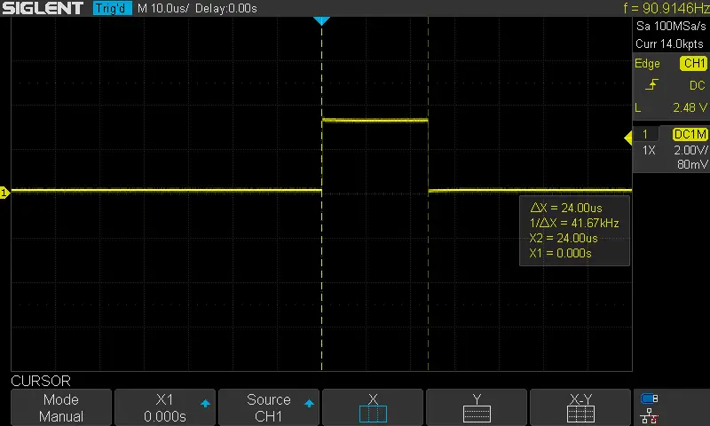
1- Joystick Read Execution Time
I’ve used a GPIO pin configured in fast mode push-pull driver output for fast edges switching on the output pin and driven it high before calling the Joystick_Read function and bring it low when it returns. And it turned out to be around 24µs which is pretty much OK. Just note that this test was done with a CPU @ 72MHz and ADC clock of 12MHz. Increasing both clock rates will guarantee a faster execution time as well as optimizing the routine code itself.
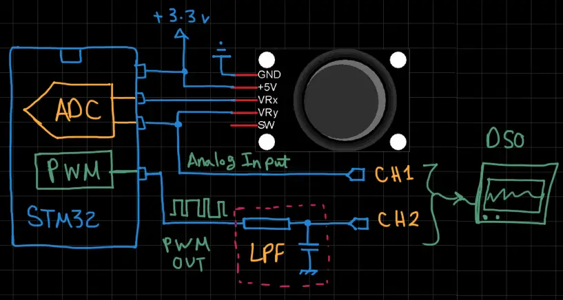
2- Joystick Analog Input Voltage VS Output PWM DC
This test is actually performed to check the validity of readings across the entire range of the Joystick analog input signal. You can use the same code provided in LAB38 and by filtering out the PWM output signal, we should be getting exactly the same voltage level as the joystick input.
In this short demo, You’ll see how to use the MATH function in a DSO just to subtract both channels and amplify the difference to examine its behavior across the entire input range. Just a quick and dirty test, nothing special about it.
3- Joystick’s Wierd Mechanical Cut-off
IDK if it’s only me or there is something wrong with these modules. If your joystick module’s price is less than 2$ like mine, then it’s most probably gonna be acting similarly. The problem I did notice is that: not the entire range of motion for the joystick is actually active! only a short distance and it reaches saturation. Don’t get me wrong, it’s still analog and linear but the range of motion is really short and most of if it is not used at all. Most of the time you’ll find yourself overdriving or underdriving the thing you’re trying to control.
I don’t know why this happens, but it gets annoying after some real-device control. Maybe a manufacturing issue or something.
Adding a digital LPF filter can help reduce any conversion noise and also add some phase delay in response which may help a little bit in this clicking problem and near-fast edge rise and fall in joystick motion, just give it a try I’m sure it’s going to make things better.
4- Joystick Analog Input Voltage Noise
Finally, I did also notice a little bit of noise on the analog input channel lines of the joystick and it can be for various reasons like power supply bad decoupling which may be the main reason behind this, and some other factors. But all in all, we can put this aside until we’re designing our PCB custom board for a specific project or application. Which I’d like to do in the future when I’m back to my new youtube channel.
Did you find this helpful? If yes, please consider supporting this work and also sharing these tutorials!
Stay tuned for the upcoming tutorials and don’t forget to SHARE these tutorials. And consider SUPPORTING this work to keep publishing free content just like this!
| Previous Tutorial | Tutorial 36 | Next Tutorial | |||||