In this tutorial, we’ll discuss how to use STM32 UART To Receive Unknown Length Data. Using the STM32 UART IDLE Line Detection hardware feature is one way to achieve the task of receiving unknown length data over UART with STM32 microcontrollers.
We’ll implement two example projects for STM32 UART IDLE Line Detection With Interrupt & DMA to practice what we’ll learn in this tutorial. Without further ado, let’s get right into it!
Table of Contents
- STM32 UART Receive Unknown Length Data
- STM32 UART IDLE Line Detection
- STM32 UART Receive Unknown Length Examples Overview
- STM32 UART IDLE Line Detection + Interrupt Example
- STM32 UART IDLE Line Detection + DMA Example
- Wrap Up
STM32 UART Receive Unknown Length Data
Many communication protocols don’t have predefined message lengths. In such situations, we need to receive an unknown length of data over UART and detect the end of each data stream so the CPU can process the received data stream. Examples include terminal commands, sensor data streams, and custom protocols. In these cases, the receiving device needs to dynamically determine and receive unknown data length.
Several techniques can be implemented to handle receiving unknown length data over UART with STM32 microcontrollers, which include:
- Time-Out Mechanism: Wait for a predefined period of inactivity to consider the end of the message. This is a very simple, yet effective, technique but can be inefficient and error-prone if the time-out value is not well-tuned.
- Fixed-Size Buffer + Overrun Detection: Allocate an RX buffer and receive the data byte-by-byte. Implement an overrun check to ensure the buffer doesn’t overflow. This approach is simple but can lose data if messages exceed the buffer size.
- Delimiter-Based Reception: Use a specific character or sequence of characters to indicate the end of the data. This technique is reliable but requires that the data communication protocol includes such delimiters. So it’s widely used for developing customized communication protocols.
- Packet Header With Data Length Info: Include a header in the data stream containing the message length. This technique adds some processing overhead but enables flexible data handling.
- UART IDLE Line Detection: Utilize the STM32’s UART hardware feature to detect periods of inactivity on the receiving line. This is what we’ll use in this tutorial’s examples and will go deeper into in the next section.
STM32 UART IDLE Line Detection
The IDLE line detection feature in STM32’s UART hardware allows the microcontroller to detect a period of inactivity on the UART line. When the line remains idle for one frame duration, an IDLE flag is set in the UART status register. This flag can trigger an interrupt, allowing the software to process the received data.
IDLE line detection is particularly useful for receiving unknown-length data because it provides a clear indication of when the transmission has ended. By using the IDLE flag, the microcontroller can determine that the sender has stopped sending data, allowing the received data to be processed without needing a predefined length or delimiter.
STM32 UART IDLE Line Detection HAL APIs (Functions)
There are 3x HAL APIs (Functions) for UART IDLE Line Detection that can be used for receiving unknown data length with STM32’s UART module. Those functions can be categorized as follows:
- Blocking: Polling
- Non-Blocking: Interrupt or DMA
The IDLE Line Detection UART Receive Functions are as follows:
|
1 2 3 |
HAL_UARTEx_ReceiveToIdle(); // Polling HAL_UARTEx_ReceiveToIdle_IT(); // Interrupt HAL_UARTEx_ReceiveToIdle_DMA(); // DMA |
Next up, we’ll implement two example projects for STM32 receiving unknown length data over UART using the IDLE Line Detection feature. First, we’ll do it with interrupt, and in the second example, we’ll do it with DMA. There is no point in doing it using polling as it’ll not be very useful for most of you despite it being doable!
STM32 UART Receive Unknown Length Examples Overview
In the following two example projects, we’ll receive an unknown length of data bytes from the PC terminal and echo back the received data. So in the testing, we’ll expect to see back whatever data we send through the terminal.
The STM32 microcontroller will automatically detect the message reception completion, determine the length of the data received, and send it back to the PC over UART. So we can execute the whole test procedure in the serial monitor.
STM32 UART IDLE Line Detection + Interrupt Example
Step #1
Open STM32CubeMX, create a new project, and select the target microcontroller.
Step #2
Enable UART1 and leave the default configurations as is without a change (9600 baud rate).
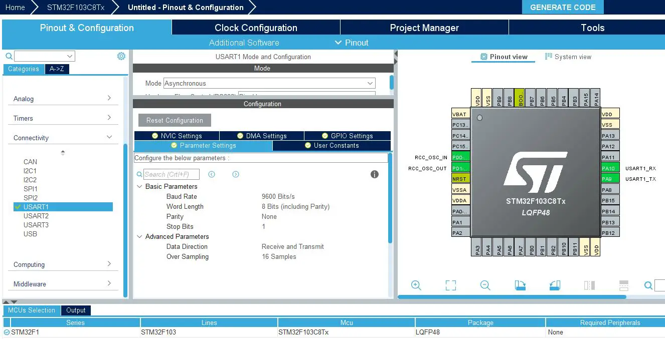
Enable The USART1 Global Interrupt From The NVIC Settings Tab

Step #3
Go to the RCC clock configuration page and enable the HSE external crystal oscillator input.

Step #4
Go to the clock configurations page, and select the HSE as a clock source, PLL output, and type in 72MHz for the desired output system frequency. Hit the “ Enter” key, and let the application solve for the required PLL dividers/multipliers to achieve the desired clock rate.

Step #5
Name & Generate The Project Initialization Code For CubeIDE or The IDE You’re Using.
STM32 UART IDLE Line Detection Interrupt Example Code
Here is The Application Code For This LAB (main.c)
|
1 2 3 4 5 6 7 8 9 10 11 12 13 14 15 16 17 18 19 20 21 22 23 24 25 26 27 28 29 30 31 32 33 34 35 36 37 |
/* * LAB Name: STM32 UART Rx Unknown Data Length (IDLE Line Detection) + Interrupt * Author: Khaled Magdy * For More Info Visit: www.DeepBlueMbedded.com */ #include "main.h" #define UART_RX_BUFFER_SIZE 40 uint8_t UART1_RxBuffer[UART_RX_BUFFER_SIZE] = {0}; uint16_t RxDataLen = 0; UART_HandleTypeDef huart1; void SystemClock_Config(void); static void MX_GPIO_Init(void); static void MX_USART1_UART_Init(void); int main(void) { HAL_Init(); SystemClock_Config(); MX_GPIO_Init(); MX_USART1_UART_Init(); HAL_UARTEx_ReceiveToIdle_IT(&huart1, UART1_RxBuffer, UART_RX_BUFFER_SIZE); while (1) { // Nothing ToDo Here! } } void HAL_UARTEx_RxEventCallback(UART_HandleTypeDef *huart, uint16_t Size) { RxDataLen = Size; HAL_UART_Transmit(&huart1, UART1_RxBuffer, RxDataLen, 100); HAL_UARTEx_ReceiveToIdle_IT(&huart1, UART1_RxBuffer, UART_RX_BUFFER_SIZE); } |
Code Explanation
In the main() function, we Call the HAL_UARTEx_ReceiveToIdle_IT() to start the reception of UART data in the UART1_RxBuffer using IDLE line detection in interrupt mode.
The Rx interrupt is fired and the ISR function HAL_UARTEx_RxEventCallback() is called whenever the hardware detects an IDLE event or we’ve already received the maximum buffer length of data UART_RX_BUFFER_SIZE. In the ISR Callback function:
- Save the received data length (size) into the RxDataLen variable
- Echo back the received data over UART to the PC using the HAL_UART_Transmit() function
- Re-start the UART data reception with IDLE line detection in interrupt mode again, and so on…
STM32 UART Receive Unknown Length Example Testing
This is the testing result on the serial monitor showing the echo message which is exactly what we’ve sent to the STM32 microcontroller. The message I’ve sent from the PC to the STM32 microcontroller has been received in the UART1_RxBuffer array as you can see in the live expressions window of the debugger.
Pay attention to the line where I’ve placed the breakpoint as you’ll need to add this breakpoint to perform the same testing as shown below. Also, note that the received message length is correctly detected and stored in the RxDataLen variable.

STM32 UART IDLE Line Detection + DMA Example
This second example project is exactly the same as the previous one. However, in this example, the transfer of the received UART data to the global array variable will be handled through the DMA unit instead of the CPU.
Step #1
Open STM32CubeMX, create a new project, and select the target microcontroller.
Step #2
Enable UART1 and leave the default configurations as is without a change (9600 baud rate).
Enable The USART1 Global Interrupt From The NVIC Settings Tab
Add A DMA Channel For UART RX From The DMA Tab With The Following Settings

Step #3
Go to the RCC clock configuration page and enable the HSE external crystal oscillator input.
Step #4
Go to the clock configurations page, and select the HSE as a clock source, PLL output, and type in 72MHz for the desired output system frequency. Hit the “ Enter” key, and let the application solve for the required PLL dividers/multipliers to achieve the desired clock rate.
Step #5
Name & Generate The Project Initialization Code For CubeIDE or The IDE You’re Using.
STM32 UART IDLE Line Detection DMA Example Code
Here is The Application Code For This LAB (main.c)
|
1 2 3 4 5 6 7 8 9 10 11 12 13 14 15 16 17 18 19 20 21 22 23 24 25 26 27 28 29 30 31 32 33 34 35 36 37 38 39 40 41 |
/* * LAB Name: STM32 UART Rx Unknown Data Length (IDLE Line Detection) + DMA * Author: Khaled Magdy * For More Info Visit: www.DeepBlueMbedded.com */ #include "main.h" #define UART_RX_BUFFER_SIZE 40 uint8_t UART1_RxBuffer[UART_RX_BUFFER_SIZE] = {0}; uint16_t RxDataLen = 0; UART_HandleTypeDef huart1; DMA_HandleTypeDef hdma_usart1_rx; void SystemClock_Config(void); static void MX_GPIO_Init(void); static void MX_DMA_Init(void); static void MX_USART1_UART_Init(void); int main(void) { HAL_Init(); SystemClock_Config(); MX_GPIO_Init(); MX_DMA_Init(); MX_USART1_UART_Init(); HAL_UARTEx_ReceiveToIdle_DMA(&huart1, UART1_RxBuffer, UART_RX_BUFFER_SIZE); while (1) { // Nothing ToDo Here! } } void HAL_UARTEx_RxEventCallback(UART_HandleTypeDef *huart, uint16_t Size) { RxDataLen = Size; HAL_UART_Transmit(&huart1, UART1_RxBuffer, RxDataLen, 100); HAL_UARTEx_ReceiveToIdle_DMA(&huart1, UART1_RxBuffer, UART_RX_BUFFER_SIZE); } |
Code Explanation
In the main() function, we Call the HAL_UARTEx_ReceiveToIdle_DMA() to start the reception of UART data in the UART1_RxBuffer using IDLE line detection in DMA mode.
The Rx interrupt is fired and the ISR function HAL_UARTEx_RxEventCallback() is called whenever the hardware detects an IDLE event or we’ve already received the maximum buffer length of data UART_RX_BUFFER_SIZE. In the ISR Callback function:
- Save the received data length (size) into the RxDataLen variable
- Echo back the received data over UART to the PC using the HAL_UART_Transmit() function
- Re-start the UART data reception with IDLE line detection in DMA mode again, and so on…
STM32 UART Receive Unknown Length Example Testing
This is the testing result on the serial monitor showing the echo message which is exactly what we’ve sent to the STM32 microcontroller. The message I’ve sent from the PC to the STM32 microcontroller has been received in the UART1_RxBuffer array as you can see in the live expressions window of the debugger.
Pay attention to the line where I’ve placed the breakpoint as you’ll need to add this breakpoint to perform the same testing as shown below. Also, note that the received message length is correctly detected and stored in the RxDataLen variable.

Note That in this example we don’t wait for the DMA transfer completion because we want to capture the end of the incoming data stream and process the received message. The DMA here is only used for data transfer byte-by-byte from the UART Rx buffer register to the UART1_RxBuffer array.
Required Parts For STM32 Examples
All the example Code/LABs/Projects in this STM32 Series of Tutorials are done using the Dev boards & Electronic Parts Below:
| QTY. | Component Name | Amazon.com | AliExpress | eBay |
| 1 | STM32-F103 BluePill Board (ARM Cortex-M3 @ 72MHz) | Amazon | AliExpress | eBay |
| 1 | Nucleo-L432KC (ARM Cortex-M4 @ 80MHz) | Amazon | AliExpress | eBay |
| 1 | ST-Link V2 Debugger | Amazon | AliExpress | eBay |
| 2 | BreadBoard | Amazon | AliExpress | eBay |
| 1 | LEDs Kit | Amazon & Amazon | AliExpress | eBay |
| 1 | Resistors Kit | Amazon & Amazon | AliExpress | eBay |
| 1 | Capacitors Kit | Amazon & Amazon | AliExpress & AliExpress | eBay & eBay |
| 1 | Jumper Wires Pack | Amazon & Amazon | AliExpress & AliExpress | eBay & eBay |
| 1 | Push Buttons | Amazon & Amazon | AliExpress | eBay |
| 1 | Potentiometers | Amazon | AliExpress | eBay |
| 1 | Micro USB Cable | Amazon | AliExpress | eBay |
★ Check The Links Below For The Full Course Kit List & LAB Test Equipment Required For Debugging ★
Download Attachments
You can download all attachment files for this Article/Tutorial (project files, schematics, code, etc..) using the link below. Please consider supporting our work through the various support options listed in the link down below. Every small donation helps to keep this website up and running and ultimately supports the whole community.
Wrap Up
In conclusion, we’ve explored how to set up the STM32 UART to receive unknown data length using IDLE line detection both in interrupt mode & DMA mode. You can build on top of the examples provided in this tutorial and/or explore the other parts of this STM32 UART tutorial series linked below.

 Rx Tx Examples")


Hello
Very good Tutorial!
Have this working well, but one other feature that would be great to know is the Count of the RXdata in the DMA buffer that is below the buffer size, can this be found,
We set the DMA buffer size to 100 bytes/characters, only 90 bytes is sent, the uart idle interrupt gets triggered, in the interrupt how can I found a value of 90 after the time out interrupt is triggered
I have tried looking at uart1 count but sitting at 0 when I set a break point ??
Thanks
hi, love your tutorial, as i am a total beginner.
but i think the rx callback you should be using huart instead of &huart1