| Previous Tutorial | Tutorial 3 | Next Tutorial | |||||
| ESP32 PWM Tutorial (analogWrite) – Arduino | |||||||
| ESP32 Course Home Page ???? | |||||||
In this tutorial, you’ll learn about ESP32 PWM and how to control PWM channels in Arduino Core. But first of all, you’ll get an introduction to what’s PWM and how it works in most microcontrollers on a hardware level. Then, we’ll investigate the ESP32 PWM Hardware peripheral and check the features it does have.
Then, we’ll move to the Arduino Core libraries that implement drivers for the ESP32 LED PWM peripheral and how to use its API functions, like ledcWrite(). It’s something similar to the commonly known Arduino analogWrite() function, but with a little bit more functionality and customizations as we’ll see. Without further ado, let’s get right into it!
[toc]
Requirements For This Tutorial
Prior Knowledge
- Nothing
Software Tools
Hardware Components
You can either get the complete course kit for this series of tutorials using the link down below. Or just refer to the table for the exact components to be used in practical LABs for only this specific tutorial.
Pulse Width Modulation (PWM)
The pulse width modulation (PWM) is a technique to create a controllable waveform digital signal to be used in various applications. There are different variations of designs to implement hardware PWM in different microcontrollers devices. But they are essentially the same in terms of the final output and usage.
PWM Internal Hardware & How PWM Works?
This is a generic hardware diagram for a typical PWM peripheral.
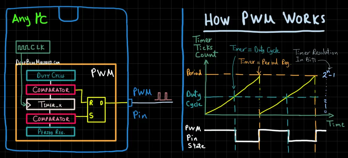
As you can see in the diagram above, the main component in a PWM signal generator is the Timer module. The timer is being clocked by a clock signal that’s derived from the main system’s clock. And it starts counting from 0 each clock cycle it increments by one.
As the timer is counting up, its value is being compared by two comparators. If it reached the Duty Cycle register value, a match signal is generated which Resets the pin state so it becomes LOW. The timer will continue counting until it reaches the Period register’s value, then the other comparator will generate a match signal which Sets the PWM pin to the HIGH state. The timer rolls over back to 0, the process is repeated, And so on!
PWM Signal Properties
A typical PWM signal has the following properties that we can control by programming the microcontroller’s PWM peripheral’s registers. Such as PWM Frequency, PWM Resolution, and PWM Duty Cycle. By changing the PWM’s duty cycle parameter, the width of the pulse does also change. Therefore, the average voltage of the waveform does also change and this creates some sort of controllable analog output (not exactly).
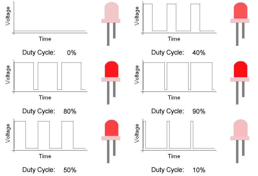
The PWM frequency is just 1/T where T is the period of each cycle. You can set the frequency to any value you want depending on what you’re trying to control. We’ll dig deeper into this in future tutorials, but for now, we’d like to dim an LED. So a PWM frequency of 1kHz will be good enough for this application.
The last PWM parameter, the Resolution is a measure for how many discrete levels of duty cycle that we can control. Look at the GIF image above, you’ll notice that the PWM duty cycle is increasing by 10% at each level. Therefore, the total discrete levels of control for the duty cycle are 10 levels. The PWM resolution = log2(Num_of_Levels) = log2(10) = 3.3 Bits.
Setting the resolution at 8 bits will give us total Duty Cycle levels of = 2n where n is the resolution (in bits). So the duty cycle entire range has 28 = 256 levels. The duty cycle values range is, therefore [ 0 – 255 ]. The higher the resolution is, the finer it gets to control the duty cycle.
ESP32 Hardware PWM
In this section, I’ll give you an introduction to the hardware capabilities for the ESP32 LED PWM peripheral, how it works, and what kind of features it has. So you can use it in an efficient way depending on the specific application requirements you have.
ESP32 PWM Pins
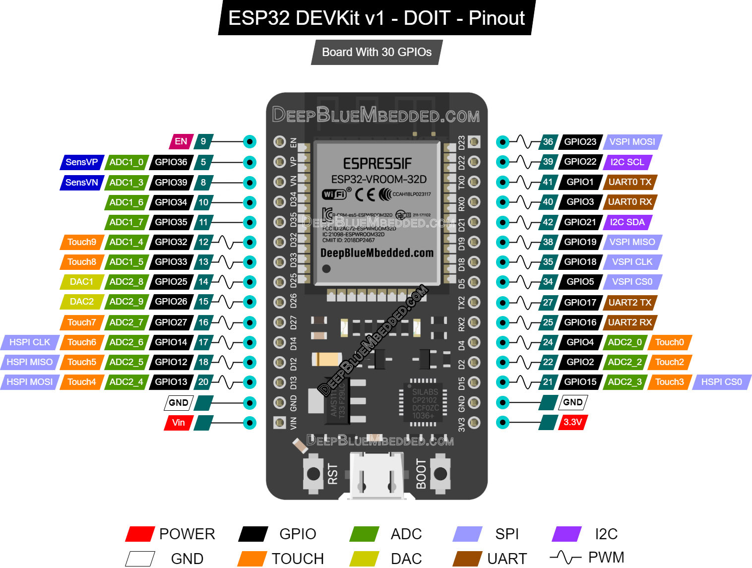
The ESP32 PWM hardware has 16 different channels, not pins. You can assign any of these channels to any GPIO pin that you want. But it has to have an output driver or in other words, it should be capable of operating as an output pin.
In our ESP32 dev boards, all the GPIO pins can be configured to operate in output mode except for 4 pins. Those pins are input only, so they don’t support PWM functionality. You can avoid those pins and you’re free to use any of the others.
Refer to this ESP32 devkit board pinout.
(if it’s not clear, right-click and open it in a new tab for a larger view)
ESP32 PWM Channels
The ESP32 PWM controller is primarily designed to control the intensity of LEDs, although it can be used to generate PWM signals for other purposes as well. It has 16 channels that can generate independent PWM waveforms.
The ESP32 PWM controller has 8 high-speed channels and 8 low-speed channels, which gives us a total of 16 channels. They’re divided into two groups depending on the speed. For each group, there are 4 timers / 8 channels. This means every two channels share the same timer. Therefore, we can’t independently control the PWM frequency of each couple of channels.
This is the ESP32 PWM hardware diagram from the datasheet.
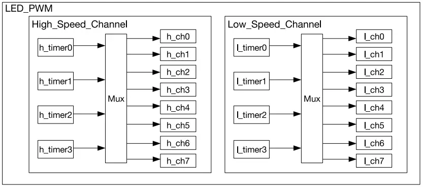
So this means we’ve got 16 channels that we can control their PWM duty cycle independently. But the frequency has to be shared between each couple of channels routed to the same timer. If you need more than 8 different PWM signals with different frequencies, you should consider looking for an external solution (e.g. I2C PWM Controller IC).
ESP32 PWM Outputs Control (in Arduino)
You can use the ESP32 PWM pins to control many devices ranging from small LEDs and up to high-power motors using MOSFET drivers and things like that. In this section, I’ll give you a step-by-step approach for what to do in order to configure and control a PWM output pin.
Step1– Decide on the PWM channel that you’re going to use [ 0 – 15 ].
Step2– Decide on the GPIO pin to route this PWM Ch signal to.
Step3– Assign that PWM Ch to the selected GPIO pin using this function.
|
1 |
ledcAttachPin(GPIO_pin, PWM_Ch); |
Step4– Decide on the required PWM Resolution for the selected channel [ 1Bit – 16Bits ]. Setting the resolution to 8Bits, gives you a duty cycle range [0 – 255]. While setting it to 10Bits, gives you a range of [ 0 – 1023 ]. And so on!
Step5– Decide on the required PWM Frequency for the selected channel. It can be anything, but for our LED dimming example let’s set it to 1kHz or (1000Hz).
Step6– Configure this PWM Channel with the selected frequency & resolution using this function.
|
1 |
ledcSetup(PWM_Ch, PWM_Freq, PWM_Res); |
Step7– Now you can control this PWM pin by changing the duty cycle using this function down below.
|
1 |
ledcWrite(PWM_Ch, DutyCycle); |
And that’s it!
| All ESP32 GPIO pins can operate in Input or Output modes. Except for the pins (34 to 39) those are input-only pins. You just can’t drive them HIGH or LOW. They’re used only in input mode. On our board, we’ve 4 of them namely (GPIO34 – GPIO35 – GPIO36 – GPIO39). They don’t support PWM functionality as well. |
Components For This Tutorial’s LABs
| QTY. | Component Name | Buy Links |
| 1 | ESP32 Devkit v1 DOIT Board | Amazon.com – eBay.com – Banggood.com |
| 2 | BreadBoard | Amazon.com – eBay.com – Banggood.com |
| 1 | Resistors Kit | Amazon.com / Amazon.com – eBay.com – Banggood.com |
| 1 | Jumper Wires Pack | Amazon.com / Amazon.com – eBay.com / eBay.com – Banggood.com |
| 1 | LEDs Kit | Amazon.com / Amazon.com – eBay.com – Banggood.com |
| 1 | Micro USB Cable | Amazon.com – eBay.com – Banggood.com |
*Affiliate Disclosure: When you click on links in this section and make a purchase, this can result in this site earning a commission. Affiliate programs and affiliations include, but are not limited to, the eBay Partner Network (EPN) and Amazon.com, Banggood.com. This may be one of the ways to support this free platform while getting your regular electronic parts orders as usual at no extra cost to you.
ESP32 PWM LED Brightness Control – LAB
| LAB Number | 5 |
| LAB Name | ESP32 PWM LED Brightness Control |
- Define & Attach The PWM GPIO pin
- Configure The PWM Channel (frequency & resolution)
- Gradually Increase the PWM’s duty cycle to max value, and gradually decrease it to the minimum value, and repeat!
Connection Diagram
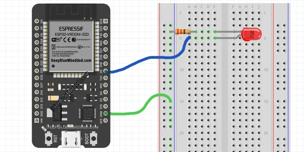
ESP32 PWM LED Control – Code Example
The code example down below does the following: We start with defining & Attaching The PWM GPIO pin. The pin I’ll be using a PWM pin is GPIO5 in this example.
Then, we’ll be configuring the PWM Channel’s frequency & resolution.
And in the main loop() function, I’ll be gradually increasing the PWM’s duty cycle to max value, and gradually decreasing it to the minimum value, and repeat!
The Full code Listing
|
1 2 3 4 5 6 7 8 9 10 11 12 13 14 15 16 17 18 19 20 21 22 23 24 25 26 27 28 29 30 31 32 33 |
/* * LAB: 5 * Name: ESP32 PWM LED Control * Author: Khaled Magdy * For More Info Visit: www.DeepBlueMbedded.com */ #define LED_GPIO 5 #define PWM1_Ch 0 #define PWM1_Res 8 #define PWM1_Freq 1000 int PWM1_DutyCycle = 0; void setup() { ledcAttachPin(LED_GPIO, PWM1_Ch); ledcSetup(PWM1_Ch, PWM1_Freq, PWM1_Res); } void loop() { while(PWM1_DutyCycle < 255) { ledcWrite(PWM1_Ch, PWM1_DutyCycle++); delay(10); } while(PWM1_DutyCycle > 0) { ledcWrite(PWM1_Ch, PWM1_DutyCycle--); delay(10); } } |
Choose the board, COM port, hold down the BOOT button, click upload and keep your finger on the BOOT button pressed. When the Arduino IDE starts sending the code, you can release the button and wait for the flashing process to be completed. Now, the ESP32 is flashed with the new firmware.
Demo Video For The Result
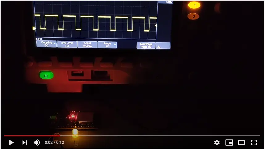
Click The image to watch the demo video on YouTube
ESP32 PWM Low Resolution vs High Resolution – LAB
| LAB Number | 6 |
| LAB Name | PWM Resolution Comparison |
- Define & Attach The PWM GPIO pin
- Configure The PWM Channel (frequency & resolution)
- Gradually Increase the PWM’s duty cycle to max value, and gradually decrease it to the minimum value, and repeat!
ESP32 PWM LED Control – Code Example
The same as the previous LAB except for the resolution is now set to only 4 bits. And the duty cycle range will be [ 0 – 15 ].
|
1 2 3 4 5 6 7 8 9 10 11 12 13 14 15 16 17 18 19 20 21 22 23 24 25 26 27 28 29 30 31 32 33 |
/* * LAB: 6 * Name: ESP32 PWM Resolution Comparison * Author: Khaled Magdy * For More Info Visit: www.DeepBlueMbedded.com */ #define LED_GPIO 5 #define PWM1_Ch 0 #define PWM1_Res 4 #define PWM1_Freq 1000 int PWM1_DutyCycle = 0; void setup() { ledcAttachPin(LED_GPIO, PWM1_Ch); ledcSetup(PWM1_Ch, PWM1_Freq, PWM1_Res); } void loop() { while(PWM1_DutyCycle < 15) { ledcWrite(PWM1_Ch, PWM1_DutyCycle++); delay(100); } while(PWM1_DutyCycle > 0) { ledcWrite(PWM1_Ch, PWM1_DutyCycle--); delay(100); } } |
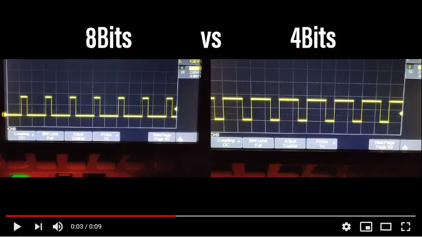
Demo Video For The Result (8Bits Vs 4Bits)
Click The image to watch the demo video on YouTube
I think it’s pretty clear in this demo video that increasing the resolution will give you way more levels of control over the PWM’s duty cycle. Which will result in very smooth and precise control.
ESP32 PWM Applications
ESP32 PWM hardware peripheral can be used in so many applications as we’ll see in the future tutorials. I’ll keep updating this series of tutorials by adding more applications and techniques that may help you in your projects. Drop me a comment if you’ve got any questions or suggestions, I’ll be glad to help!
Related Tutorials Based On ESP32 PWM
- ESP32 PWM Motor Speed Control
- ESP32 PWM Servo Motor Control
- ESP32 PWM Fan Speed Control
- And More…
Learn More About PWM in General
- PWM in 8-Bit Microcontrollers Tutorial
- PWM in ARM-Based STM32 MCUs
- Software PWM Technique (increase PWM pins count)
- Get 16-Bits Resolution PWM With a 10-Bit PWM Peripheral
You can also check the ESP32 Course Home Page ???? for more ESP32 tutorials divided into sections based on categories. This may be helpful for you in case of searching for a specific tutorial or application.
Did you find this helpful? If yes, please consider supporting this work and sharing these tutorials!
Stay tuned for the upcoming tutorials and don’t forget to SHARE these tutorials. And consider SUPPORTING this work to keep publishing free content just like this!
| ESP32 Course Home Page ???? | |||||||
| Previous Tutorial | Tutorial 3 | Next Tutorial | |||||

Hello Sir,
Thank for the article.
I want control a Dual Motor driver with PWM signal I write a code with your reference example of led.
But when I compile the code both motors are starting at a time.
Here my code for ESP 32:
*/
#define m1_pwm 5
#define m1_dir 18
#define PWM1_Ch 0
#define PWM1_Res 4
#define PWM1_Freq 1000
#define m2_pwm 19
#define m2_dir 21
#define PWM2_Ch 0
#define PWM2_Res 4
#define PWM2_Freq 1000
int PWM1_DutyCycle = 0;
int PWM2_DutyCycle = 0;
void setup()
{
ledcAttachPin(m1_pwm, PWM1_Ch);
ledcSetup(PWM1_Ch, PWM1_Freq, PWM1_Res);
ledcAttachPin(m2_pwm, PWM2_Ch);
ledcSetup(PWM2_Ch, PWM2_Freq, PWM2_Res);
}
void loop()
{
while(PWM1_DutyCycle 0)
{
ledcWrite(PWM1_Ch, PWM1_DutyCycle–);
delay(100);
}
while(PWM2_DutyCycle 0)
{
ledcWrite(PWM2_Ch, PWM2_DutyCycle–);
delay(100);
}
}