| Previous Tutorial | Tutorial 10 | Next Tutorial | |||||
| ESP32 Temperature Sensor LM35 Interfacing (Arduino) | |||||||
| ESP32 Course Home Page ???? | |||||||
In this tutorial, you’ll learn how to use ESP32 (or ESP8266) with the LM35 Temperature Sensor in Arduino IDE using ADC analog input pins. We’ll discuss how the LM35 temperature sensor works, how to connect it with ESP32, and how to get readings using ADC in Arduino IDE.
We’ll be doing 3 different LABs in this tutorial. To show the ESP32 LM35 Temperature readings on the serial port, I2C LCD, and also to get multiple temperature sensors readings at the same time. Without further ado, let’s get right into it!
In this tutorial: 3 LABs
| LAB22 | ESP32 with LM35 Temperature Sensor – Serial Monitor & Processing |
| LAB23 | ESP32 with LM35 Temperature Sensor – I2C LCD |
| LAB24 | ESP32 with Multiple LM35 Temperature Sensors |
[toc]
Requirements For This Tutorial
Prior Knowledge
Software Tools
Hardware Components
You can either get the complete course kit for this series of tutorials using the link down below. Or just refer to the table for the exact components to be used in practical LABs for only this specific tutorial.
LM35 Temperature Sensor
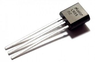
The LM35 is a temperature sensor widely used in electronic projects and midrange devices. It has limited usage in industrial applications due to maximum temperature range limitations. It’s rated to a full range of −55°C to 150°C.
You can just power it up and instantly read the voltage level on the output terminal. The VOUT of the sensor directly maps to the sensor’s temperature as we’ll see hereafter.
Technical Features of LM35 Temperature Sensor
- Linear + 10-mV/°C Scale Factor
- 0.5°C Ensured Accuracy (at 25°C)
- Rated for Full −55°C to 150°C Range
- Operates From 4 V to 30 V
- Less Than 60-μA Current Drain
- Non-Linearity Only ±¼°C Typical
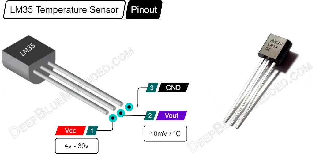
LM35 Pinout
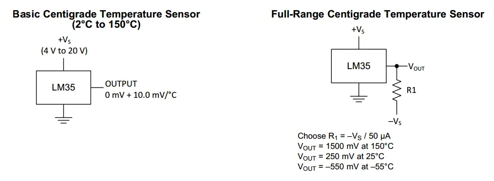
LM35 V-T Characteristics & Configurations
As stated in the LM35 temperature sensor datasheet, the accuracy specifications of the LM35 are given with respect to a simple linear transfer function:
VOUT = (10 mv / °C) × T
where VOUT is the LM35 output voltage & T is the temperature in °C. And this is what we’ll be using in code in order to convert the ADC voltage readings to temperature values (in °C or °F).
There are two possible configurations for the LM35 temperature sensor as described in the datasheet. They’re shown in the diagram down below. The first of which is the Basic Configuration (with a range of 2 °C to 150 °C).
The other configuration for LM35 is called the “Full-Range” which gives you a range for measurements between (-55 °C up to 150 °C). It also requires an additional external resistor and a negative supply voltage as indicated in the diagram below.
ESP32 LM35 Temperature Sensor Interfacing (Arduino)
In this section, we’ll see how to make the ESP32 to LM35 connections, and how to use the ESP32 ADC to take measurements of the temperature sensor in Arduino IDE.
ESP32 LM35 Temperature Sensor Connection
The connection between ESP32 & LM35 temperature sensor should be as follows. Note that you can use any other GPIO pin that has an analog input channel capability.
| LM35 Temperature Sensor | ESP32 DevKit v1 Board |
| VOUT | GPIO35 |
| VCC | Vin |
| GND | GND |
Using ESP32 ADC With LM35 Sensor (in Arduino)
| Note that: I’ll be using the ESP32 ADC Calibration routine (By Espressif implemented in Arduino Core) to get temperature readings as accurate as possible. This topic was discussed in more detail in the ESP32 ADC Tutorial if you want to check it out. |
Here are the exact steps you need to follow in order to read an LM35 temperature sensor with ESP32 boards (using ADC calibrated) + a line-by-line code explanation.
Step1– Include the Arduino Core ADC Calibration Library Header File
| #include “esp_adc_cal.h” |
Step2– Define the LM35 sensor GPIO pin to be used as an ADC analog input channel
| #define LM35_Sensor1 35 |
Step3– Now, create 4 variables: an int to hold the raw ADC reading, 3 x float to hold the final temperature measurement (in °C and/or °F), and a temporary voltage variable as we’ll need it in the calculations.
| int LM35_Raw_Sensor1 = 0;
float LM35_TempC_Sensor1 = 0.0; float LM35_TempF_Sensor1 = 0.0; float Voltage = 0.0; |
Step4– Add this ADC Read & Calibration Function to your code
|
1 2 3 4 5 6 7 |
uint32_t readADC_Cal(int ADC_Raw) { esp_adc_cal_characteristics_t adc_chars; esp_adc_cal_characterize(ADC_UNIT_1, ADC_ATTEN_DB_11, ADC_WIDTH_BIT_12, 1100, &adc_chars); return(esp_adc_cal_raw_to_voltage(ADC_Raw, &adc_chars)); } |
Step5– Now, in the main loop function, you can read the ADC, get the calibrated voltage vlaue, and convert it to temperature (in °C and/or °F).
|
1 2 3 4 5 6 7 8 9 10 11 12 13 14 15 16 17 18 19 20 |
void loop() { // Read LM35_Sensor1 ADC Pin LM35_Raw_Sensor1 = analogRead(LM35_Sensor1); // Calibrate ADC & Get Voltage (in mV) Voltage = readADC_Cal(LM35_Raw_Sensor1); // TempC = Voltage(mV) / 10 LM35_TempC_Sensor1 = Voltage / 10; LM35_TempF_Sensor1 = (LM35_TempC_Sensor1 * 1.8) + 32; // Print The Readings Serial.print("Temperature = "); Serial.print(LM35_TempC_Sensor1); Serial.print(" °C , "); Serial.print("Temperature = "); Serial.print(LM35_TempF_Sensor1); Serial.println(" °F"); delay(100); } |
| Note that: ADC Noise and readings fluctuation should be minimal after applying the calibration technique shown in the code above. However, you can still improve this after eliminating ADC noise by using a simple digital filter (like the moving average) to get temperature readings as accurate as possible. This topic was also discussed in detail in the ESP32 ADC Tutorial if you want to check it out. |
Components For This Tutorial’s LABs
| QTY. | Component Name | Buy Links |
| 1 | ESP32 Devkit v1 DOIT Board | Amazon.com – eBay.com – Banggood.com |
| 2 | BreadBoard | Amazon.com – eBay.com – Banggood.com |
| 1 | Resistors Kit | Amazon.com / Amazon.com – eBay.com – Banggood.com |
| 1 | Jumper Wires Pack | Amazon.com / Amazon.com – eBay.com / eBay.com – Banggood.com |
| 1 | LEDs Kit | Amazon.com / Amazon.com – eBay.com – Banggood.com |
| 1 | Micro USB Cable | Amazon.com – eBay.com – Banggood.com |
| 2 | I2C LCD Module | Amazon.com Amazon.com – eBay.com – Banggood.com |
| 2 | LM35 Temperature Sensors | Amazon.com – eBay.com – Banggood.com |
*Affiliate Disclosure: When you click on links in this section and make a purchase, this can result in this site earning a commission. Affiliate programs and affiliations include, but are not limited to, the eBay Partner Network (EPN) and Amazon.com, Banggood.com. This may be one of the ways to support this free platform while getting your regular electronic parts orders as usual at no extra cost to you.
ESP32 Temperature Sensor LM35 – Serial Print
| LAB Number | 22 |
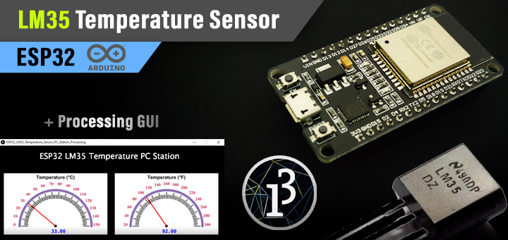
| LAB Name | ESP32 Temperature Sensor LM35 – Serial Print + Processing Gauge Example |
- Read the temperature using ADC calibrated routine
- Print the readings over the UART serial port
- Keep repeating…
ESP32 Temperature Sensor LM35 – Arduino Code Example
The Full code Listing
|
1 2 3 4 5 6 7 8 9 10 11 12 13 14 15 16 17 18 19 20 21 22 23 24 25 26 27 28 29 30 31 32 33 34 35 36 37 38 39 40 41 42 43 44 45 46 47 48 49 |
/* * LAB: 22 * Name: ESP32 LM35 Temperature Sensor + Serial * Author: Khaled Magdy * For More Info Visit: www.DeepBlueMbedded.com */ #include "esp_adc_cal.h" #define LM35_Sensor1 35 int LM35_Raw_Sensor1 = 0; float LM35_TempC_Sensor1 = 0.0; float LM35_TempF_Sensor1 = 0.0; float Voltage = 0.0; void setup() { Serial.begin(115200); } void loop() { // Read LM35_Sensor1 ADC Pin LM35_Raw_Sensor1 = analogRead(LM35_Sensor1); // Calibrate ADC & Get Voltage (in mV) Voltage = readADC_Cal(LM35_Raw_Sensor1); // TempC = Voltage(mV) / 10 LM35_TempC_Sensor1 = Voltage / 10; LM35_TempF_Sensor1 = (LM35_TempC_Sensor1 * 1.8) + 32; // Print The Readings Serial.print("Temperature = "); Serial.print(LM35_TempC_Sensor1); Serial.print(" °C , "); Serial.print("Temperature = "); Serial.print(LM35_TempF_Sensor1); Serial.println(" °F"); delay(100); } uint32_t readADC_Cal(int ADC_Raw) { esp_adc_cal_characteristics_t adc_chars; esp_adc_cal_characterize(ADC_UNIT_1, ADC_ATTEN_DB_11, ADC_WIDTH_BIT_12, 1100, &adc_chars); return(esp_adc_cal_raw_to_voltage(ADC_Raw, &adc_chars)); } |
Choose the board, COM port, hold down the BOOT button, click upload and keep your finger on the BOOT button pressed. When the Arduino IDE starts sending the code, you can release the button and wait for the flashing process to be completed. Now, the ESP32 is flashed with the new firmware.
Hardware Connections
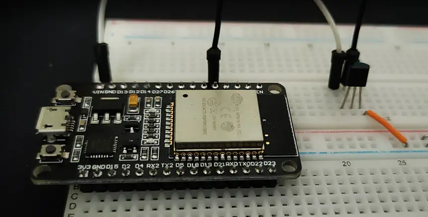
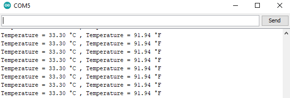
Here is The Result
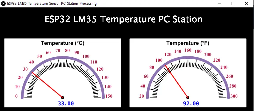
ESP32 LM35 Temperature Sensor PC Station (With Processing)
This is the same example, but we’ll do a little bit of modification in the ESP32 Arduino code. And also you’ll need to have installed Processing on your machine. Then, copy the processing code provided down below in a new sketch and run it directly to see the GUI temperature meters window.
ESP32 Code
replace the loop() function in the previous (ESP32 Arduino Code example) by this one shown below.
|
1 2 3 4 5 6 7 8 9 10 11 12 13 14 15 |
// Use this loop() for Processing Example void loop() { // Read LM35_Sensor1 ADC Pin LM35_Raw_Sensor1 = analogRead(LM35_Sensor1); // Calibrate ADC & Get Voltage (in mV) Voltage = readADC_Cal(LM35_Raw_Sensor1); // TempC = Voltage(mV) / 10 LM35_TempC_Sensor1 = Voltage / 10; LM35_TempF_Sensor1 = (LM35_TempC_Sensor1 * 1.8) + 32; // Print The Readings Serial.println(LM35_TempC_Sensor1); delay(100); } |
Processing Code
Replace the COM port name in the code down below with your COM port name for your ESP32 board. That could be easily found in the device manager if you’re using windows.
|
1 2 3 4 5 6 7 8 9 10 11 12 13 14 15 16 17 18 19 20 21 22 23 24 25 26 27 28 29 30 31 32 33 34 35 36 37 38 39 40 41 42 43 44 45 46 47 48 49 50 51 52 53 54 55 56 57 58 59 60 61 62 63 64 65 66 67 68 69 70 71 72 73 74 75 76 77 78 79 80 81 82 |
import meter.*; import processing.serial.*; Serial port; Meter M1, M2; void setup() { size(850, 350); background(0); port = new Serial(this, "COM5", 115200); fill(120, 50, 0); M1 = new Meter(this, 10, 100); // Adjust font color of meter value + M1.setMeterWidth(400); M1.setTitleFontSize(20); M1.setTitleFontName("Arial bold"); M1.setTitle("Temperature (°C)"); M1.setDisplayDigitalMeterValue(true); // Meter Scale String[] scaleLabelsT = {"0", "10", "20", "30", "40", "50", "60", "70", "80", "90", "100", "110", "120", "130", "140", "150"}; M1.setScaleLabels(scaleLabelsT); M1.setScaleFontSize(18); M1.setScaleFontName("Times New Roman bold"); M1.setScaleFontColor(color(200, 30, 70)); M1.setArcColor(color(141, 113, 178)); M1.setArcThickness(10); M1.setMaxScaleValue(150); M1.setNeedleThickness(3); M1.setMinInputSignal(0); M1.setMaxInputSignal(150); // A second meter for reference int mx = M1.getMeterX(); int my = M1.getMeterY(); int mw = M1.getMeterWidth(); M2 = new Meter(this, mx + mw + 20, my); M2.setMeterWidth(400); M2.setTitleFontSize(20); M2.setTitleFontName("Arial bold"); M2.setTitle("Temperature (°F)"); M2.setDisplayDigitalMeterValue(true); String[] scaleLabelsH = {"20", "40", "60", "80", "100", "120", "140", "160", "180", "200", "220", "240", "260", "280", "300"}; M2.setScaleLabels(scaleLabelsH); M2.setScaleFontSize(18); M2.setScaleFontName("Times New Roman bold"); M2.setScaleFontColor(color(200, 30, 70)); M2.setArcColor(color(141, 113, 178)); M2.setArcThickness(10); M2.setMaxScaleValue(300); M2.setNeedleThickness(3); M2.setMinInputSignal(0); M2.setMaxInputSignal(300); } public void draw() { textSize(30); fill(255, 255, 255); text("ESP32 LM35 Temperature PC Station", 150, 50); if (port.available() > 0) { String val = port.readString(); float TempC = float(val); float TempF = (TempC * 1.8) + 32; M1.updateMeter(int(TempC)); M2.updateMeter(int(TempF)); } } |
Here is The Result
ESP32 Temperature Sensor LM35 – I2C LCD
| LAB Number | 23 |
| LAB Name | ESP32 Temperature Sensor LM35 + I2C LCD Display |
- Include the libraries
- Define an object of LiquidCrystal_I2C, set its parameters, and initialize the LCD
- Read the ADC calibrated value & convert it to temperature
- Print the temperature to the I2C LCD display
- Keep repeating…
ESP32 Temperature Sensor LM35 + I2C LCD – Arduino Code
The Full code Listing
|
1 2 3 4 5 6 7 8 9 10 11 12 13 14 15 16 17 18 19 20 21 22 23 24 25 26 27 28 29 30 31 32 33 34 35 36 37 38 39 40 41 42 43 44 45 46 47 48 49 50 51 52 53 54 55 56 57 58 |
/* * LAB: 23 * Name: ESP32 LM35 Temperature Sensor + I2C LCD * Author: Khaled Magdy * For More Info Visit: www.DeepBlueMbedded.com */ #include <Wire.h> #include <LiquidCrystal_I2C.h> #include "esp_adc_cal.h" #define LM35_Sensor1 35 LiquidCrystal_I2C I2C_LCD1(0x27, 16, 2); // set the LCD address to 0x27 for a 16 chars and 2 line display int LM35_Raw_Sensor1 = 0; float LM35_TempC_Sensor1 = 0.0; float LM35_TempF_Sensor1 = 0.0; float Voltage = 0.0; void setup() { // Initialize The I2C LCD I2C_LCD1.init(); // Turn ON The Backlight I2C_LCD1.backlight(); } void loop() { // Read LM35_Sensor1 ADC Pin LM35_Raw_Sensor1 = analogRead(LM35_Sensor1); // Calibrate ADC & Get Voltage (in mV) Voltage = readADC_Cal(LM35_Raw_Sensor1); // TempC = Voltage(mV) / 10 LM35_TempC_Sensor1 = Voltage / 10; LM35_TempF_Sensor1 = (LM35_TempC_Sensor1 * 1.8) + 32; // Print The Readings To LCD I2C_LCD1.setCursor(0, 0); I2C_LCD1.print("Temperature: "); I2C_LCD1.setCursor(0, 1); I2C_LCD1.print(LM35_TempC_Sensor1); I2C_LCD1.print(" C, "); I2C_LCD1.print(LM35_TempF_Sensor1); I2C_LCD1.print(" F"); delay(100); } uint32_t readADC_Cal(int ADC_Raw) { esp_adc_cal_characteristics_t adc_chars; esp_adc_cal_characterize(ADC_UNIT_1, ADC_ATTEN_DB_11, ADC_WIDTH_BIT_12, 1100, &adc_chars); return(esp_adc_cal_raw_to_voltage(ADC_Raw, &adc_chars)); } |
Choose the board, COM port, hold down the BOOT button, click upload and keep your finger on the BOOT button pressed. When the Arduino IDE starts sending the code, you can release the button and wait for the flashing process to be completed. Now, the ESP32 is flashed with the new firmware.
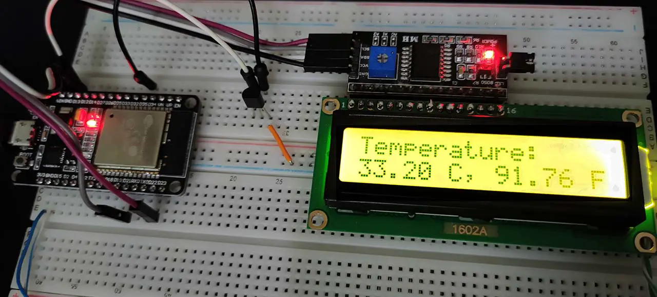
The connection between ESP32 & I2C LCD module should be as follows.
| PCF8574 I2C LCD Module | ESP32 DevKit v1 Board |
| SCL | GPIO22 |
| SDA | GPIO21 |
| Vcc | Vin |
| GND | GND |
Here is The Result
ESP32 Multiple Temperature Sensors LM35
| LAB Number | 24 |
| LAB Name | ESP32 Multiple Temperature Sensors LM35 + I2C LCD |
- Include the libraries
- Define an object of LiquidCrystal_I2C, set its parameters, and initialize the LCD
- Read the 2ch ADC calibrated value & convert it to temperature (for LM35 sensor 1 & 2)
- Print the temperatures to the I2C LCD display
- Keep repeating…
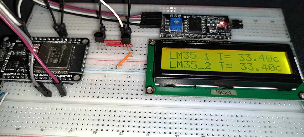
ESP32 Multiple Temperature Sensors LM35 + I2C LCD
This LAB example is very similar to the previous one. Except for the fact that here we’ll be using 2 LM35 sensors connected to 2 different analog input channels. So, we’ll take the measurement for the sensors one by one, and then we’ll print the readings to the I2C LCD as usual.
The Full code Listing
|
1 2 3 4 5 6 7 8 9 10 11 12 13 14 15 16 17 18 19 20 21 22 23 24 25 26 27 28 29 30 31 32 33 34 35 36 37 38 39 40 41 42 43 44 45 46 47 48 49 50 51 52 53 54 55 56 57 58 59 60 61 62 63 64 65 |
/* * LAB: 24 * Name: ESP32 Multi LM35 Temperature Sensors + I2C LCD * Author: Khaled Magdy * For More Info Visit: www.DeepBlueMbedded.com */ #include <Wire.h> #include <LiquidCrystal_I2C.h> #include "esp_adc_cal.h" #define LM35_Sensor1 35 #define LM35_Sensor2 32 LiquidCrystal_I2C I2C_LCD1(0x27, 16, 2); // set the LCD address to 0x27 for a 16 chars and 2 line display int LM35_Raw = 0; float Voltage = 0.0; float LM35_TempC_Sensor1 = 0.0; float LM35_TempC_Sensor2 = 0.0; void setup() { // Initialize The I2C LCD I2C_LCD1.init(); // Turn ON The Backlight I2C_LCD1.backlight(); } void loop() { // Read LM35_Sensor1 ADC Pin LM35_Raw = analogRead(LM35_Sensor1); // Calibrate ADC & Get Voltage (in mV) Voltage = readADC_Cal(LM35_Raw); // TempC = Voltage(mV) / 10 LM35_TempC_Sensor1 = Voltage / 10; // Read LM35_Sensor2 ADC Pin LM35_Raw = analogRead(LM35_Sensor2); // Calibrate ADC & Get Voltage (in mV) Voltage = readADC_Cal(LM35_Raw); // TempC = Voltage(mV) / 10 LM35_TempC_Sensor2 = Voltage / 10; // Print The Readings To LCD I2C_LCD1.setCursor(0, 0); I2C_LCD1.print("LM35_1 T= "); I2C_LCD1.print(LM35_TempC_Sensor1); I2C_LCD1.print("c"); I2C_LCD1.setCursor(0, 1); I2C_LCD1.print("LM35_2 T= "); I2C_LCD1.print(LM35_TempC_Sensor2); I2C_LCD1.print("c"); delay(100); } uint32_t readADC_Cal(int ADC_Raw) { esp_adc_cal_characteristics_t adc_chars; esp_adc_cal_characterize(ADC_UNIT_1, ADC_ATTEN_DB_11, ADC_WIDTH_BIT_12, 1100, &adc_chars); return(esp_adc_cal_raw_to_voltage(ADC_Raw, &adc_chars)); } |
Choose the board, COM port, hold down the BOOT button, click upload and keep your finger on the BOOT button pressed. When the Arduino IDE starts sending the code, you can release the button and wait for the flashing process to be completed. Now, the ESP32 is flashed with the new firmware.
Here is The Result
ESP32 Temperature Sensor LM35 Applications
Temperature sensors like LM35 can be used in so many applications as we’ll see in future tutorials. I’ll keep updating this series of tutorials by adding more applications and techniques that may help you in your projects. Drop me a comment if you’ve got any questions or suggestions, I’ll be glad to help!
Related Tutorials Based On ESP32 Temperature Sensors
- ESP32 I2C LCD Display Interfacing Tutorial
- ESP32 LM35 Temperature Sensor Webserver
- And More…
Learn More About LM35 Sensor
You can also check the ESP32 Course Home Page ???? for more ESP32 tutorials divided into sections based on categories. This may be helpful for you in case of searching for a specific tutorial or application.
Did you find this helpful? If yes, please consider supporting this work and sharing these tutorials!
Stay tuned for the upcoming tutorials and don’t forget to SHARE these tutorials. And consider SUPPORTING this work to keep publishing free content just like this!
| ESP32 Course Home Page ???? | |||||||
| Previous Tutorial | Tutorial 10 | Next Tutorial | |||||