This is a comprehensive guide on how ESP32 DAC works and its different modes of operation as well as generating Audio with ESP32 in Arduino IDE. We’ll discuss the theoretical concepts first, then we’ll create some examples for ESP32 DAC applications like generating Sine waveforms, Analog Output (DC Voltage) with the ESP32 internal DAC, and finally creating some ESP32 Audio music.
The application examples that we’ll create in this tutorial are as follows:
- ESP32 Analog Output (DC Voltage) With DAC
- ESP32 Sine Wave Generation
- ESP32 Audio Music With DAC + Touch PADs
Table of Contents
- Digital To Analog Converter (DAC)
- ESP32 DAC
- ESP32 DAC Arduino Core APIs
- ESP32 Analog Output DC Voltage
- ESP32 Sine Wave Generation
- ESP32 Audio Output With DAC
- ESP32 DAC Concluding Remarks
- Download Attachments
Digital To Analog Converter (DAC)
A digital-to-analog converter (DAC) is an electronic circuit that converts a digital signal to an analog signal. This process is essential in many applications, including audio playback and industrial control systems. A DAC generally takes a binary value as input and outputs the corresponding analog voltage to this digital number.
The resolution of a DAC determines the number of possible output voltages (discrete voltage levels), and the accuracy of the DAC determines how closely the output voltages match the desired analog values.
You can definitely check out the tutorial down below in case you’d like to go deeper into how DAC works, types of DACs, DAC errors, and much more details about D/A converters.

This article will give more in-depth information about D/A converters (DACs) in microcontrollers, their types, operation, error sources, practical applications, simulation, etc. It’s worth checking if you’re new to this topic.
ESP32 DAC
ESP32 has two 8-Bit resolution DAC Channels: (DAC_CHANNEL_1 and DAC_CHANNEL_2) which correspond to the following pins (GPIO25 and GPIO26) on most ESP32 boards. For ESP32-S2 they’re (GPIO17 and GPIO18) respectively.
ESP32 DAC Channels Pinout
| ESP32 SoC | DAC_CH_1 | DAC_CH_2 |
| ESP32 | GPIO25 | GPIO26 |
| ESP32-S2 | GPIO17 | GPIO18 |
You can refer to this ESP32 Pinout to find out the DAC output channels.

ESP32 DAC Output Range
Given that the analog reference voltage for ESP32 is 3.3v, we’d expect the DAC to “ideally” have an output swing from 0v up to 3.3v when we give it a digital input in the range of 0 up to 255. And it should “ideally” be a linear relationship.
ESP32 DAC Speed
Speaking of the ESP32 DAC Speed, you can run the built-in ESP32 DAC for up to 5µS update rate using the following API.
#include <driver/dac.h>
...
dac_output_voltage(DAC_CH1, Val);
The generic Arduino dacWrite() API is still functional with the ESP32 boards and it doesn’t require including any other file unlike the API shown above. But it lacks speed, as it was updating at a much slower rate, taking around 20µS for each sample update at max speed.
dacWrite(DAC_CH1, Val);
For maximum sampling rate, you’d definitely need to use the DMA in conjunction with your DAC to transfer the digital samples from a memory buffer to the DAC as fast as possible.
ESP32 DAC Modes of Operation
The ESP32 DAC can operate in 3 different modes which we’ll briefly explain here in this tutorial and will go deeper into each mode in future articles as we’ll be only using the first mode in the examples here in this tutorial.
- Direct Voltage Output Mode
- Continuous Analog Output With DMA
- Cosine WaveForm Output With Cosine Wave Generator (CWG)
1. ESP32 DAC Direct Voltage Output Mode
This is the easiest and most straightforward mode, you simply write the digital (8-Bit) output to the DAC and it’ll convert it to the corresponding analog voltage level on the DAC output channel that you’ve selected. The voltage will stay constant until you send a new digital sample to the DAC. It’s also referred to as “One-Shot Mode” or “Direct Mode”, it’s the same thing.
2. ESP32 DAC DMA Continuous Output Mode
The ESP32 DAC channels can use the DMA (Direct Memory Access) in order to continuously generate analog output waveforms (patterns) without much CPU intervention, thanks to the DMA. This can go in 3 different ways as illustrated below:
- Synchronous Writing: The data in the DMA buffer is continuously transferred to the DAC (a blocking way of operation). This means, no more data can be sent to the buffer until the transfer operation is done. And it’s the fastest way to transfer a chunk of audio buffer for playback for example.
- Asynchronous Writing: The data in the DMA buffer is transferred to the DAC one by one asynchronously (a non-blocking way of operation). This means the DMA will keep going through the data buffer based on a callback trigger that indicates the end of the previous transfer so the operation can keep repeating without blocking the system.
- Cyclical Writing: The data is loaded once to the DMA buffer and it’ll keep looping through the data and send it to the DAC one by one until it’s done. Then, it’ll repeat from the beginning of the data buffer without the need to re-load the buffer, unlike the 2 previous modes. It’s very efficient for pattern/waveform generation applications.
The ESP32-IDF has very good documentation and APIs for those modes and we’ll be using those modes in future tutorials.
3. ESP32 DAC Cosine Wave Generator Mode
The ESP32 DAC has a built-in cosine waveform generator that can directly give you a cosine waveform on the selected output channel with controllable frequency, amplitude, and phase shift. The ESP32 DAC Frequency Output is 130Hz-100kHz using this cosine generator.
ESP32 DAC Arduino Core APIs
You can use the Arduino built-in DAC write function for ESP32 and it’s going to work without a problem. Just note that it takes more time to update the output than the ESP32 Driver that you can use by including the file “driver/dac.h”.
ESP32 Arduino-Core APIs
dacWrite(): This function is used to send the output sample data to the dac channel on the specified pin for the selected dac channel.
dacWrite(uint8_t dac_pin, uint8_t value);
dacDisable(): This function is used to disable the DAC output on a given pin (DAC channel).
void dacDisable(uint8_t dac_pin);
Both APIs mentioned above don’t require any additional includes or libraries to work.
ESP32 DAC Driver
The ESP32 drivers are still under ongoing development and enhancement, therefore there are many versions up till now. And the ESP32 DAC driver specifically is experiencing a re-structure and things are probably going to change in the near future. I’ll definitely keep you updated with the latest validated/tested information. But for now, we’ll be using the latest stable version as the new driver is not yet released at the time of writing this tutorial, but I’ll give you a hint for what is going on in this section.
The OLD+New DAC Driver File Structuer

| OLD DAC Driver | New DAC Driver |
|
include only this: <driver/dac.h> |
include all of the following: <driver/dac_oneshot.h> <driver/dac_cosine.h> <driver/dac_continuous.h> |
|
You can use the old APIs: dac_pad_get_io_num(dac_channel_t channel, gpio_num_t *gpio_num); dac_output_enable(dac_channel_t channel); dac_output_disable(dac_channel_t channel); dac_output_voltage(dac_channel_t channel, uint8_t dac_value); dac_cw_generator_enable(void); dac_cw_generator_disable(void); dac_cw_generator_config(dac_cw_config_t *cw);
|
You can use the new APIs: Check it’s latest updates and current state at Espressif website. We’ll cover it here when it’s fully integrated. |
| Note that: the old driver can’t co-exist with the new driver. You can only include either dac.h file or the new 3 headers in your project. You can’t use both old and new in the same application. And also note that the old driver may be replaced and removed in the future. | |
The ESP32 DAC (old driver) APIs That We’ll Be Using In This Tutorial Examples:
//Get the GPIO number of a specific DAC channel
dac_pad_get_io_num(dac_channel_t channel, gpio_num_t *gpio_num);
// DAC channel output enable
dac_output_enable(dac_channel_t channel);
// DAC channel output disable
dac_output_disable(dac_channel_t channel);
// Set DAC channel output voltage
dac_output_voltage(dac_channel_t channel, uint8_t dac_value);

// Config the cosine wave generator function in DAC module
dac_cw_generator_config(dac_cw_config_t *cw);
// Enable cosine wave generator output
dac_cw_generator_enable(void);
// Disable cosine wave generator output
dac_cw_generator_disable(void);
ESP32 Analog Output DC Voltage
You can typically use the ESP32 built-in DAC to generate an analog output DC voltage which will remain constant until you update the value of the DAC buffer register. The digital input value is 8-Bit because the ESP32 DAC is 8-Bit in resolution and the output is an analog voltage level on the DAC_CHANNEL pin. Use the following formula to find out the analog output that corresponds to any digital input value.

ESP32 DAC Example (Arduino IDE)
In this first example, we’ll use the ESP32 DAC to generate some constant voltage levels and insert some time delay after each analog voltage output is applied in order to have some time that allows us to take the measurement with an AVOmeter in order to validate the functionality.
Wiring
Here is how to hook up the output to the voltmeter for testing & measurement.

Example Code
/*
 * LAB Name: ESP32 DAC Direct Voltage Output Example
 * Author: Khaled Magdy
 * DeepBlueMbedded 2023
 * For More Info Visit: www.DeepBlueMbedded.com
*/

#define DAC_CH1 25

void setup()
{
  // DO NOTHING
}

void loop()
{
  // Send Output DC Voltage Raw Values To The DAC
  // (0  64  128 192 255)
  // Insert Delay After Each Sample Output
  dacWrite(DAC_CH1, 0);
  delay(3500);
  dacWrite(DAC_CH1, 64);
  delay(3500);
  dacWrite(DAC_CH1, 128);
  delay(3500);
  dacWrite(DAC_CH1, 192);
  delay(3500);
  dacWrite(DAC_CH1, 255);
  delay(3500);
}
Code Explanation
In this example, we’re sending some constant values to the DAC with the dacWrite() function. Which takes the number of the GPIO pin and the digital value to be sent to the DAC.
Testing Results

As you can obviously see, there is a slight deviation from the measured actual output voltage of the DAC and the theoretical expected voltages that you can get using the formula shown earlier. Therefore, we can conclude that the DAC output will always have a slight error in the voltage output. The most obvious parts are the zero-drift (around 0.08v @ 0 input) and the early saturation (around 3.165v @ 255 max input value).
Here is a plot for the ESP32 DAC characteristic output vs the ideal behavior that it should (theoretically) have.

ESP32 DAC has a slight error in the output voltage compared to the ideal (expected) behavior. It has a small zero-drift (about 0.08v) and saturates early before the 3.3v V_ref limit (around 3.165v). No external V_ref can be supplied for compensation, unlike various other microcontrollers.
ESP32 Sine Wave Generation
There are so many ways for Sine wave generation with ESP32 and so are the applications for that. Today, we’ll use it for an audio signal generation but it can be used for numerous other applications as well.
The easiest way to generate a sine wave with ESP32 is probably to use the built-in DAC feature for CWG and you’ll get a clean sinusoidal waveform with controllable frequency, amplitude, and phase.
But in the next example, I’ll use another well-known technique that is widely used in embedded applications and hopefully will give some space for you to learn some new concepts. We’ll be using a LookUpTable alongside with timer interrupt to generate the sampling time interval @ which we’ll be updating the DAC output buffer with the LookUpTable values cyclically.
|
Sine LookUpTable Generator Tool You can use this online sine lookup-table generator tool to get the array of values that represent amplitude for a full cycle of sin waveform. Click “Generate“ And copy the code with the LookUpTable Array. |
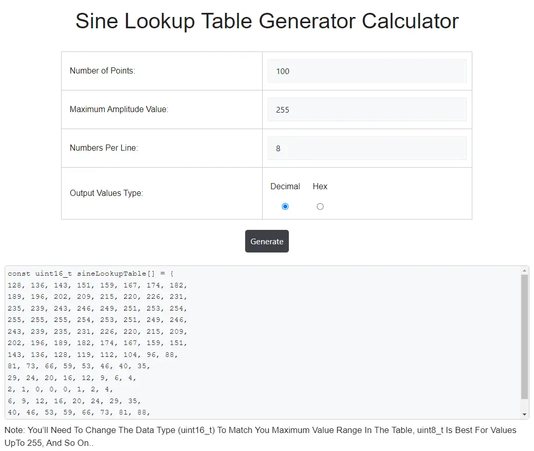 |
We now have sine lookup table and the next step is to configure one of the ESP32 timers to generate a fixed time interval interrupt event that represents the “Sampling Time” for the DAC output. For this, you’ll need to recall the “ESP32 Timers Tutorial” which explains this topic in detail. And for now, we can briefly say that setting the DAC sampling time will be done using the following formula for ESP32 timers.

Where T_OUT is the desired timer interrupt interval (DAC sampling time). And APB_CLK is 80MHz by default, this leaves to us the choice for the values of TimerTicks & Prescaler values in order to achieve the desired T_OUT (sampling time for the DAC).
For the next example, here is how the calculations start.
- Decide on the desired DAC sampling rate for your project. Let’s say 100kHz (100ksps)
- This means the sample time is 1/F_sampling = 1/100,000 = 10µS
- So now we need to set the timer interrupt time interval to be 10µS, Therefore, T_OUT = 10µS
- Using the ESP32 Timer Equation above, We can select Prescaler = 80 and TimerTicks = 10 To Achieve the requirement of (T_OUT = 10µS)
And that’s all about it!

This article will give more in-depth information about ESP32 Timers and how to properly set the desired timer interrupt interval for ESP32 applications and all the calculations that you’d go through to achieve your design goals.
ESP32 Sine Wave Example
In this example, we’ll use ESP32 DAC to generate a Sine waveform with a frequency of 1kHz. We’ll use a DAC sampling rate of 100kHz (100ksps). Therefore, the LookUpTable length has to be 100 sample points. And here is the equation that controls the output sine waveform frequency.

The output Sine waveform signal’s frequency is equal to 1 / (Number of sample points “table length” x DAC_Sampling_Time)
Output_Sine_Frequency = 1 / (100 x 10µS) = 1kHz
And that is what we actually need. For changing the output sine waveform’s frequency, you have to change the DAC_Sampling_Rate and use the formula shown above to help you determine the needed sample time to get the desired output frequency. Given that we keep the lookup table’s length (Ns) fixed.
Don’t attempt increasing the DAC sampling rate above 100ksps because @ 100ksps, you’ll have 100,000 timer interrupts per second. Each of these arrives every 10µS and takes up to 5µS to complete execution. So we’re talking about a CPU load of 50% at least. Which is an inefficient way of doing this application and a huge drawback of this technique. This puts the highlight on the DMA and how it can tremendously offload the CPU of doing hectic tasks, just like this!
If you need a higher output frequency and still want to use the timer interrupt method instead of DMA, you better go with decreasing the Ns (or the sine lookup table length) and deal with the distorted sine wave output by adding a simple RC filter to reduce the distortion.
Wiring
Here is how to hook up the output signal to the oscilloscope.

Example Code
/*
 * LAB Name: ESP32 Sine Wave Generation Example
 * Author: Khaled Magdy
 * DeepBlueMbedded 2023
 * For More Info Visit: www.DeepBlueMbedded.com
*/

#include <driver/dac.h>

// Timer0 Configuration Pointer (Handle)
hw_timer_t *Timer0_Cfg = NULL;

// Sine LookUpTable & Index Variable
uint8_t SampleIdx = 0;
const uint8_t sineLookupTable[] = {
128, 136, 143, 151, 159, 167, 174, 182,
189, 196, 202, 209, 215, 220, 226, 231,
235, 239, 243, 246, 249, 251, 253, 254,
255, 255, 255, 254, 253, 251, 249, 246,
243, 239, 235, 231, 226, 220, 215, 209,
202, 196, 189, 182, 174, 167, 159, 151,
143, 136, 128, 119, 112, 104, 96, 88,
81, 73, 66, 59, 53, 46, 40, 35,
29, 24, 20, 16, 12, 9, 6, 4,
2, 1, 0, 0, 0, 1, 2, 4,
6, 9, 12, 16, 20, 24, 29, 35,
40, 46, 53, 59, 66, 73, 81, 88,
96, 104, 112, 119};

// The Timer0 ISR Function (Executes Every Timer0 Interrupt Interval)
void IRAM_ATTR Timer0_ISR()
{
  // Send SineTable Values To DAC One By One
  dac_output_voltage(DAC_CHANNEL_1, sineLookupTable[SampleIdx++]);
  if(SampleIdx == 100)
  {
    SampleIdx = 0;
  }
}

void setup()
{
  // Configure Timer0 Interrupt
  Timer0_Cfg = timerBegin(0, 80, true);
  timerAttachInterrupt(Timer0_Cfg, &Timer0_ISR, true);
  timerAlarmWrite(Timer0_Cfg, 10, true);
  timerAlarmEnable(Timer0_Cfg);
  // Enable DAC1 Channel's Output
  dac_output_enable(DAC_CHANNEL_1);
}

void loop()
{
  // DO NOTHING
}
Code Explanation
As stated earlier, the goal of this example is to generate a sine waveform using the ESP32 DAC with a frequency of 1kHz. The DAC sampling rate is set to 100ksps by configuring Timer0 to generate an interrupt each 10µS. This is essentially what we’re doing in the setup() function. And we also enable the selected DAC channel which is (DAC_CHANNEL_1).
void setup()
{
  // Configure Timer0 Interrupt
  Timer0_Cfg = timerBegin(0, 80, true);
  timerAttachInterrupt(Timer0_Cfg, &Timer0_ISR, true);
  timerAlarmWrite(Timer0_Cfg, 10, true);
  timerAlarmEnable(Timer0_Cfg);
  // Enable DAC1 Channel's Output
  dac_output_enable(DAC_CHANNEL_1);
}
For each 10µS, the Timer0 will generate an interrupt signal, and we need to send the output sample to the DAC from the lookup-table every timer interrupt interval. So, the Timer ISR (interrupt service routine) function is doing this exactly. The index variable is used to keep track of the sample number in the table array and it rolls over back to 0 when it reaches the end of the table (at index = 100).
// The Timer0 ISR Function (Executes Every Timer0 Interrupt Interval)
void IRAM_ATTR Timer0_ISR()
{
  // Send SineTable Values To DAC One By One
  dac_output_voltage(DAC_CHANNEL_1, sineLookupTable[SampleIdx++]);
  if(SampleIdx == 100)
  {
    SampleIdx = 0;
  }
}
The Loop() function doesn’t need to do anything, as we’re handling the needed logic operations in the Timer0_ISR.
Testing Results
As you can see on the oscilloscope screen, it’s a perfect sinusoidal waveform @ 1kHz exactly as we planned for.

ESP32 Audio Output With DAC
There are so many ways to generate audio with ESP32 microcontroller boards. But we’ll continue using the DAC + Timer interrupt as in the previous example. The upcoming example will also include touch pads reading for input to generate different tones.
The output of the DAC can’t be used directly to drive the speaker (load). That’s why we’ll be using the LM386 audio power amplifier (or any other audio amplifier available to you).
ESP32 Audio Music With DAC + TouchPADs
In this example, we’ll read 4 different touch pads and will generate a different tone for each touchpad as long as it’s “touched”. When the user release the pad, the audio tone shall stop immediately.
The Arduino code example for this application is very similar to the previous example but it only have 2 main additional operations going on. The first one, is we declare and read 4 touch pads for the input detection, and the sine waveform frequency control is done by changing the DAC_Sampling_Rate or in other words the Timer0_Interrupt time interval. They are essentially the same thing DAC_Sampling_Freq = (1/TimerInterrupt_TimeInterval).
The 4 tones we’ll generate have the following frequencies: (200Hz, 500Hz, 1000Hz, 1428Hz). Use the equations from the previous example to validate the required configurations to achieve each frequency or to implement your own set of tones if you need to.
Keep the sample points count (Ns) that represent the lookuptable lenght as fixed. Decide on your desired output frequency (F_out) and solve for (Ts) the required Time interval for Timer0 interrupt (which is the DAC sampling time).
Wiring
Here is how to hook up the ESP32 with LM386 audio power amplifier and a speaker. And also attach the touchPADs which can be any copper/aluminum pieces you’ve available or just any bare wires to touch. Capacitive touch sensing works perfectly with different surface materials that you may have around.

Example Code
/*
 * LAB Name: ESP32 Audio Music With DAC Example
 * Author: Khaled Magdy
 * DeepBlueMbedded 2023
 * For More Info Visit: www.DeepBlueMbedded.com
*/

#include <driver/dac.h>

// Define The TouchPAD Pins (You Can Add More Or Less)
#define TOUCHPAD_1 12
#define TOUCHPAD_2 13
#define TOUCHPAD_3 14
#define TOUCHPAD_4 15

// Define The Touch Threshold Value For Your TouchPADs
#define TOUCH_THR 20

// Array To Hold TouchPADs Readings (4 TouchPADs)
int TOUCHPAD_Values[4] = {0};

// Timer0 Configuration Pointer (Handle)
hw_timer_t *Timer0_Cfg = NULL;

// Variable To Control The TMR0 Auto-Reload Register Value In Order To Change The TimerInterrupt Interval
// Which Enable Us To Control The Output WaveForm's Frequency
uint64_t TMR0_ARR_Val = 10;

// Sine LookUpTable & Index Variable
uint8_t SampleIdx = 0;
const uint8_t sineLookupTable[100] = {
128, 136, 143, 151, 159, 167, 174, 182,
189, 196, 202, 209, 215, 220, 226, 231,
235, 239, 243, 246, 249, 251, 253, 254,
255, 255, 255, 254, 253, 251, 249, 246,
243, 239, 235, 231, 226, 220, 215, 209,
202, 196, 189, 182, 174, 167, 159, 151,
143, 136, 128, 119, 112, 104, 96, 88,
81, 73, 66, 59, 53, 46, 40, 35,
29, 24, 20, 16, 12, 9, 6, 4,
2, 1, 0, 0, 0, 1, 2, 4,
6, 9, 12, 16, 20, 24, 29, 35,
40, 46, 53, 59, 66, 73, 81, 88,
96, 104, 112, 119};

// The Timer0 ISR Function (Executes Every Timer0 Interrupt Interval)
void IRAM_ATTR Timer0_ISR()
{
  // Send SineTable Values To DAC One By One
  dac_output_voltage(DAC_CHANNEL_1, sineLookupTable[SampleIdx++]);
  if(SampleIdx == 100)
  {
    SampleIdx = 0;
  }
}

void setup()
{
  // Configure Timer0 Interrupt
  Timer0_Cfg = timerBegin(0, 80, true);
  timerAttachInterrupt(Timer0_Cfg, &Timer0_ISR, true);
  timerAlarmWrite(Timer0_Cfg, TMR0_ARR_Val, true);
  timerAlarmEnable(Timer0_Cfg);
  // Disable DAC1 Channel's Output
  dac_output_disable(DAC_CHANNEL_1);
}

void loop()
{
  // Read The Touch PADs
  TOUCHPAD_Values[0] = touchRead(TOUCHPAD_1);
  TOUCHPAD_Values[1] = touchRead(TOUCHPAD_2);
  TOUCHPAD_Values[2] = touchRead(TOUCHPAD_3);
  TOUCHPAD_Values[3] = touchRead(TOUCHPAD_4);

  if(TOUCHPAD_Values[0] < TOUCH_THR)  // Play 200Hz Tone
  {
    TMR0_ARR_Val = 50;
    dac_output_enable(DAC_CHANNEL_1);
  }
  else if(TOUCHPAD_Values[1] < TOUCH_THR) // Play 500Hz Tone
  {
    TMR0_ARR_Val = 20;
    dac_output_enable(DAC_CHANNEL_1);
  }
  else if(TOUCHPAD_Values[2] < TOUCH_THR) // Play 1000Hz Tone
  {
    TMR0_ARR_Val = 10;
    dac_output_enable(DAC_CHANNEL_1);
  }
  else if(TOUCHPAD_Values[3] < TOUCH_THR)  // Play 1428Hz Tone
  {
    TMR0_ARR_Val = 7;
    dac_output_enable(DAC_CHANNEL_1);
  }
  else
  {
    dac_output_disable(DAC_CHANNEL_1);
  }
  // Update The Timer Interrupt Interval According To The Desired Tone
  timerAlarmWrite(Timer0_Cfg, TMR0_ARR_Val, true);
}
Code Explanation
The main loop() function starts by reading the 4 touch PADs and checking if any is “touched”. The threshold value will change depending on your touch pad material and surface. If a pad is touched, we change the Timer0 auto-reload register’s value, wich in turn changes the timer interrupt interval. This will increase/decrease the DAC sampling rate and ultimately change the output sine waveform’s frequency.
We finally assign the updated value of the Timer0_ARR depending on which pad is currently touched. If none is touched, we disable the DAC output.
void loop()
{
  // Read The Touch PADs
  TOUCHPAD_Values[0] = touchRead(TOUCHPAD_1);
  TOUCHPAD_Values[1] = touchRead(TOUCHPAD_2);
  TOUCHPAD_Values[2] = touchRead(TOUCHPAD_3);
  TOUCHPAD_Values[3] = touchRead(TOUCHPAD_4);

  if(TOUCHPAD_Values[0] < TOUCH_THR)  // Play 200Hz Tone
  {
    TMR0_ARR_Val = 50;
    dac_output_enable(DAC_CHANNEL_1);
  }
  else if(TOUCHPAD_Values[1] < TOUCH_THR) // Play 500Hz Tone
  {
    TMR0_ARR_Val = 20;
    dac_output_enable(DAC_CHANNEL_1);
  }
  else if(TOUCHPAD_Values[2] < TOUCH_THR) // Play 1000Hz Tone
  {
    TMR0_ARR_Val = 10;
    dac_output_enable(DAC_CHANNEL_1);
  }
  else if(TOUCHPAD_Values[3] < TOUCH_THR)  // Play 1428Hz Tone
  {
    TMR0_ARR_Val = 7;
    dac_output_enable(DAC_CHANNEL_1);
  }
  else
  {
    dac_output_disable(DAC_CHANNEL_1);
  }
  // Update The Timer Interrupt Interval According To The Desired Tone
  timerAlarmWrite(Timer0_Cfg, TMR0_ARR_Val, true);
}
Testing Results
This is how it turned out at the end.
ESP32 DAC Concluding Remarks
To conclude this tutorial, we’ll highlight the fact that you can use many different ways to generate waveforms using ESP32 boards. We’ll re-visit this topic again in the future and introduce more efficient techniques to generate audio signals and waveforms. Stay tuned!
Parts List
Here is the full components list for all parts that you’d need in order to perform the practical LABs mentioned here in this article and for the whole ESP32 series of tutorials found here on DeepBlueMbedded. Please, note that those are affiliate links and we’ll receive a small commission on your purchase at no additional cost to you, and it’d definitely support our work.
Download Attachments
You can download all attachment files for this Article/Tutorial (project files, schematics, code, etc..) using the link below. Please consider supporting my work through the various support options listed in the link down below. Every small donation helps to keep this website up and running and ultimately supports our community.