| Previous Tutorial | Tutorial 9 | Next Tutorial | |||||
| ESP32 I2C LCD in Arduino IDE | PCF8574 I2C LCD Module | |||||||
| ESP32 Course Home Page ???? | |||||||
In this tutorial, you’ll learn how to use ESP32 (or ESP8266) with the I2C LCD Display module (PCF8574) in Arduino IDE. We’ll be using the LiquidCrystal_I2C library with I2C Wire.h library in Arduino Core to interface LCD 16×2 display via the I2C bus.
The library APIs are very similar to the standard LiquidCrystal library in Arduino that we’ve used in this previous tutorial. Except for the fact that it does use the I2C bus instead of parallel (4-Bit) data mode. Which does save a lot of GPIO pins and very suitable for many projects.
We’ll be using this a lot in future tutorials, so I hope you can follow and do all the LABs listed below successfully. Without further ado, let’s get right into it!
In this tutorial: 4 LABs
| LAB18 | ESP32 with Single I2C LCD Display Unit – Static Text |
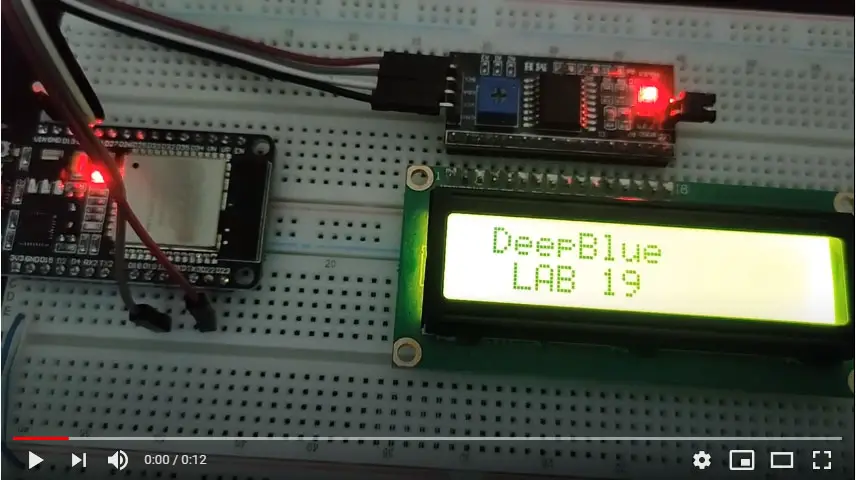
| LAB19 | ESP32 with Single I2C LCD Display Unit – Scrolling Text |
| LAB20 | ESP32 with Single I2C LCD Display Unit – Custom Characters |
| LAB21 | ESP32 with Multi I2C LCD Display Units (2 or more) |
[toc]
Requirements For This Tutorial
Prior Knowledge
Software Tools
Hardware Components
You can either get the complete course kit for this series of tutorials using the link down below. Or just refer to the table for the exact components to be used in practical LABs for only this specific tutorial.
I2C LCD Module (PCF8574)
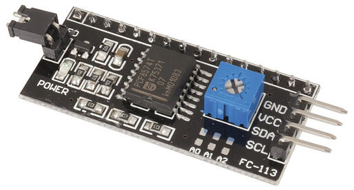
The I2C IO expander IC (PCF8574) is commonly used as a cheap solution to implement an I2C LCD interface that replaces the classic parallel connection to the LCDs (at least 6 pins) with an easy to use I2C bus (only 2 pins).
Moreover, it’s shared with all I2C devices on the bus, so you can still have so many other modules/sensors connected on the same bus. In this previous article, I’ve demonstrated everything about this IC using its datasheet and build a driver library (in Embedded-C) for this IC. You can check it out if you’re interested in learning more about it.
In this section, we’ll only discuss the important things in order to get started with these modules as quickly as possible and control them with ESP32 or ESP8266 boards.
I2C LCD Module Default Address
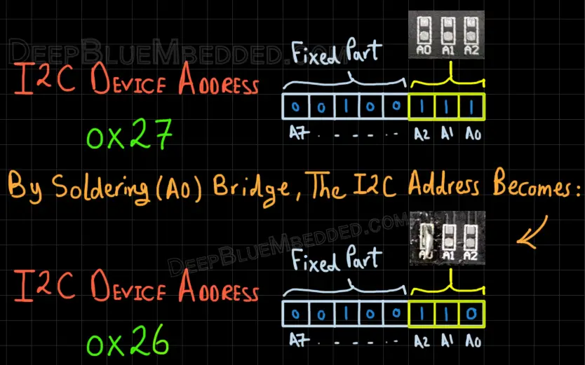
The default address for the PCF8574 IC as stated in its datasheet is shown in the figure down below. It also shows you that 3 bits of the address are actually controllable by the user. You can solder these solder bridges to change the I2C address of the device.
This will allow multiple I2C LCD modules to be connected on the same I2C bus at the same time which we’ll be doing actually hereafter (in LAB21).

Changing The I2C LCD Module Default Address
As you know, the 3 non-fixed value bits in the address allow us to make 8 different combinations. And potentially be able to use up to 8 different I2C LCD devices on the same bus at the same time.
Here, I’ll solder the A0 bridge which forces the LSB in the address to become 0. Therefore, the I2C device address is now 0x26 instead of the default value 0x27.
Now, I’ve got 2 I2C LCD modules with 2 unique addresses (0x27, 0x26). And those are the two I’ll be using in LAB21 to show you how to use multiple I2C LCDs with ESP32 at the same time. All of this information does apply to any number of modules up to 8 on the same bus.
ESP32 (or ESP8266) LiquidCrystal_I2C LCD in Arduino
In this section, I’ll show you the library we’ll be using (LiquidCrystal_I2C), how to install it in Arduino IDE, how to make the ESP32 to I2C LCD module connections, and what are different API functions available to use in the library.
Installing LiquidCrystal_I2C Library in Arduino IDE
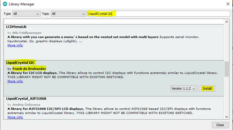
The library we’ll be using is called “LiquidCrysal_I2C”. It can be added manually by visiting GitHub and downloading the files to the Arduino directory. Or just by using the library manager within Arduino IDE itself, and this is what we’ll be doing hereafter.
Open Arduino IDE. Go to Sketch > Include Library > Manage Libraries…
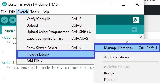
And search for the LiquidCrystal I2C library and hit install. It’ll be automatically installed and added to your default Arduino libraries directory. If, for some reason, it didn’t complete properly. Then, you can try adding it manually after downloading it from GitHub.
ESP32 I2C LCD Module Connection
The connection between ESP32 & I2C LCD module should be as follows. Note that the Wire library by default uses the I2C0 module & its default pins are GPIO21 & GPIO22, as we’ve stated in the previous I2C tutorial.
| PCF8574 I2C LCD Module | ESP32 DevKit v1 Board |
| SCL | GPIO22 |
| SDA | GPIO21 |
| Vcc | Vin |
| GND | GND |
ESP8266 I2C LCD Module Connection
The connection between ESP8266 NodeMCU & I2C LCD module should be as follows
| PCF8574 I2C LCD Module | ESP8266 NodeMCU Board |
| SCL | GPIO5 (D1) |
| SDA | GPIO4 (D2) |
| Vcc | Vin |
| GND | GND |
Using ESP32 LiquidCrystal_I2C Library in Arduino
Here are the exact steps you need to follow in order to use this library in your projects with a line-by-line code explanation.
Step1– Include the Arduino Core I2C wire library + LiquidCrysal I2C library as well
| #include <Wire.h>
#include <LiquidCrystal_I2C.h> |
Step2– Define an object of the LiquidCrystal_I2C and pass to it (the I2C device address, Num of cols in LCD, Num of rows in LCD)
| LiquidCrystal_I2C I2C_LCD1(0x27, 16, 2); |
Step3– Now, you can initialize the LCD in the setup function and turn ON its backlight LED
| // Initialize The I2C LCD I2C_LCD1.init(); // Turn ON The Backlight I2C_LCD1.backlight(); |
Step4– Just write whatever you want to the LCD using the print function as follows
| I2C_LCD1.print(“Hello World!”); |
Other Functions (APIs) You Can Use in different projects:
- home() – Return to the home position (0, 0)
- setCursor() – Set the cursor position (x, y)
- cursor() – Show the cursor
- noCursor() – Hide the cursor
- blink() – Make the cursor blink in its location
- noBlink() – Turn OFF cursor blink animation
- display() – Turn ON the display (written text will show up)
- noDisplay() – Turn OFF the display to save power (text remains in memory)
- scrollDisplayLeft() – Shift the entire display to the left by one position (needs to be called repeatedly)
- scrollDisplayRight() – Shift the entire display to the right by one position (needs to be called repeatedly)
Components For This Tutorial’s LABs
| QTY. | Component Name | Buy Links |
| 1 | ESP32 Devkit v1 DOIT Board | Amazon.com – eBay.com – Banggood.com |
| 2 | BreadBoard | Amazon.com – eBay.com – Banggood.com |
| 1 | Resistors Kit | Amazon.com / Amazon.com – eBay.com – Banggood.com |
| 1 | Jumper Wires Pack | Amazon.com / Amazon.com – eBay.com / eBay.com – Banggood.com |
| 1 | LEDs Kit | Amazon.com / Amazon.com – eBay.com – Banggood.com |
| 1 | Micro USB Cable | Amazon.com – eBay.com – Banggood.com |
| 2 | I2C LCD Module | Amazon.com Amazon.com – eBay – Banggood.com |
*Affiliate Disclosure: When you click on links in this section and make a purchase, this can result in this site earning a commission. Affiliate programs and affiliations include, but are not limited to, the eBay Partner Network (EPN) and Amazon.com, Banggood.com. This may be one of the ways to support this free platform while getting your regular electronic parts orders as usual at no extra cost to you.
ESP32 LiquidCrystal_I2C LCD Module – Static Text
| LAB Number | 18 |
| LAB Name | ESP32 I2C LCD – Static Text |
- Include the libraries
- Define an object of LiquidCrystal_I2C, set its parameters, and initialize the LCD
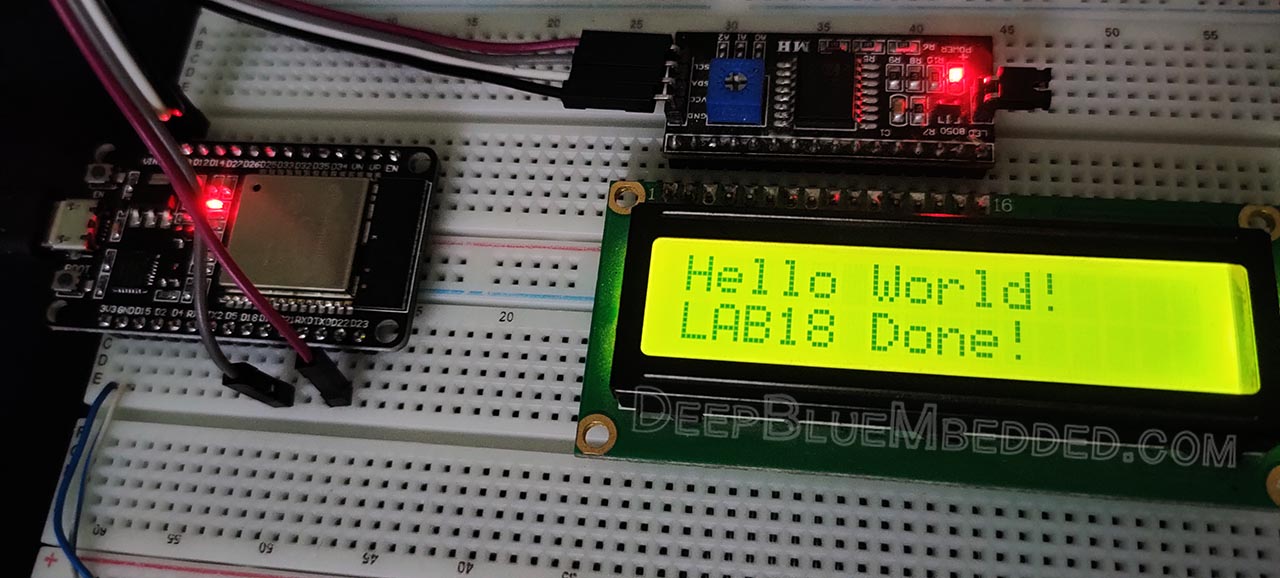
- Print “Hello World!” at home position
- Set the cursor to the 2nd row & print another string of text
ESP32 I2C LCD Static Text – Arduino Code Example
The code example down below does the following: We start with defining an object of LiquidCrystal_I2C, set its parameters, and initialize the LCD. Then, we’ll print “Hello World!” at the home position. Next, we’ll set the cursor to point at the 2nd row and print another string of text. And that’s all!
The Full code Listing
|
1 2 3 4 5 6 7 8 9 10 11 12 13 14 15 16 17 18 19 20 21 22 23 24 25 26 27 28 29 30 31 |
/* * LAB: 18 * Name: ESP32 I2C LCD - Static Text * Author: Khaled Magdy * For More Info Visit: www.DeepBlueMbedded.com */ #include <Wire.h> #include <LiquidCrystal_I2C.h> LiquidCrystal_I2C I2C_LCD1(0x27, 16, 2); // set the LCD address to 0x27 for a 16 chars and 2 line display void setup() { // Initialize The I2C LCD I2C_LCD1.init(); // Turn ON The Backlight I2C_LCD1.backlight(); // Print A Message To The 1st Line I2C_LCD1.print("Hello World!"); // Set Cursor To Line 2 I2C_LCD1.setCursor(0,1); // Print A Message To The 2nd Line I2C_LCD1.print("LAB18 Done!"); } void loop() { // Do Nothing... } |
Choose the board, COM port, hold down the BOOT button, click upload and keep your finger on the BOOT button pressed. When the Arduino IDE starts sending the code, you can release the button and wait for the flashing process to be completed. Now, the ESP32 is flashed with the new firmware.
The connection between ESP32 & I2C LCD module should be as follows.
| PCF8574 I2C LCD Module | ESP32 DevKit v1 Board |
| SCL | GPIO22 |
| SDA | GPIO21 |
| Vcc | Vin |
| GND | GND |
Here is The Result
ESP32 LiquidCrystal_I2C LCD Module – Scrolling Text
| LAB Number | 19 |
| LAB Name | ESP32 I2C LCD – Scrolling Text |
- Include the libraries
- Define an object of LiquidCrystal_I2C, set its parameters, and initialize the LCD
- Write a 2-lines message
- Shift the entire display to the right 7 times, then to the left 7 times, and repeat!
ESP32 I2C LCD Scrolling Text – Arduino Code Example
The Full code Listing
|
1 2 3 4 5 6 7 8 9 10 11 12 13 14 15 16 17 18 19 20 21 22 23 24 25 26 27 28 29 30 31 32 33 34 35 36 37 38 39 40 41 |
/* * LAB: 19 * Name: ESP32 I2C LCD - Scrolling Text * Author: Khaled Magdy * For More Info Visit: www.DeepBlueMbedded.com */ #include <Wire.h> #include <LiquidCrystal_I2C.h> LiquidCrystal_I2C I2C_LCD1(0x27, 16, 2); void setup() { // Initialize The I2C LCD I2C_LCD1.init(); // Turn ON The Backlight I2C_LCD1.backlight(); // Print A Message To The 1st Line I2C_LCD1.print("DeepBlue"); // Set Cursor To Line 2 I2C_LCD1.setCursor(0,1); // Print A Message To The 2nd Line I2C_LCD1.print(" LAB 19"); } void loop() { // Shift The Entire Display To Right 7 Times for(int i=0; i<7; i++) { I2C_LCD1.scrollDisplayRight(); delay(500); } // Shift The Entire Display To Left 7 Times for(int i=0; i<7; i++) { I2C_LCD1.scrollDisplayLeft(); delay(500); } } |
Choose the board, COM port, hold down the BOOT button, click upload and keep your finger on the BOOT button pressed. When the Arduino IDE starts sending the code, you can release the button and wait for the flashing process to be completed. Now, the ESP32 is flashed with the new firmware.
Demo Video For The Result
Click The image to watch the demo video on YouTube
ESP32 LiquidCrystal_I2C LCD Module – Custom Characters
| LAB Number | 20 |
| LAB Name | ESP32 I2C LCD – Custom Characters |
- Include the libraries
- Define an object of LiquidCrystal_I2C, set its parameters, and initialize the LCD
- Create your custom character using any tool (like this online tool)
- Write a string to the LCD and append to it the new character you’ve just created and added
Display Custom Characters – Arduino Code Example
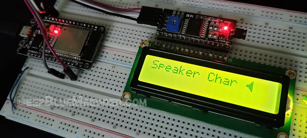
The LCD display’s controller (Hitachi HD44780) supports up to 8 custom characters that you can create and store on the LCD itself. Then you can send the Index of each custom character to be displayed later. Maybe 8 custom characters are not enough for your project, but it’s one little extra feature that you can occasionally use.
The Full code Listing
|
1 2 3 4 5 6 7 8 9 10 11 12 13 14 15 16 17 18 19 20 21 22 23 24 25 26 27 28 29 30 31 32 33 34 35 36 37 38 39 40 41 42 43 44 |
/* * LAB: 20 * Name: ESP32 I2C LCD - Custom Characters * Author: Khaled Magdy * For More Info Visit: www.DeepBlueMbedded.com */ #include <Wire.h> #include <LiquidCrystal_I2C.h> LiquidCrystal_I2C I2C_LCD1(0x27, 16, 2); // set the LCD address to 0x27 for a 16 chars and 2 line display byte SpeakerChar[8] = { B00001, B00011, B00111, B11111, B11111, B00111, B00011, B00001 }; void setup() { // Initialize The I2C LCD I2C_LCD1.init(); // Turn ON The Backlight I2C_LCD1.backlight(); // Create a Custom Character (Speaker) I2C_LCD1.createChar(0, SpeakerChar); // Display The First Message In Home Position (0, 0) I2C_LCD1.setCursor(0, 0); I2C_LCD1.print("Speaker Char "); // Append The New Char To The Message // Note That: byte(0) Now Represents Our 1st New Custom Char I2C_LCD1.write(byte(0)); } void loop() { // Do Nothing... } |
Choose the board, COM port, hold down the BOOT button, click upload and keep your finger on the BOOT button pressed. When the Arduino IDE starts sending the code, you can release the button and wait for the flashing process to be completed. Now, the ESP32 is flashed with the new firmware.
Here is The Result
ESP32 Multiple I2C LCDs Modules (in Arduino)
| LAB Number | 21 |
| LAB Name | ESP32 Multiple I2C LCDs |
- Include the libraries
- Define two objects of LiquidCrystal_I2C, set their parameters, and initialize both LCDs
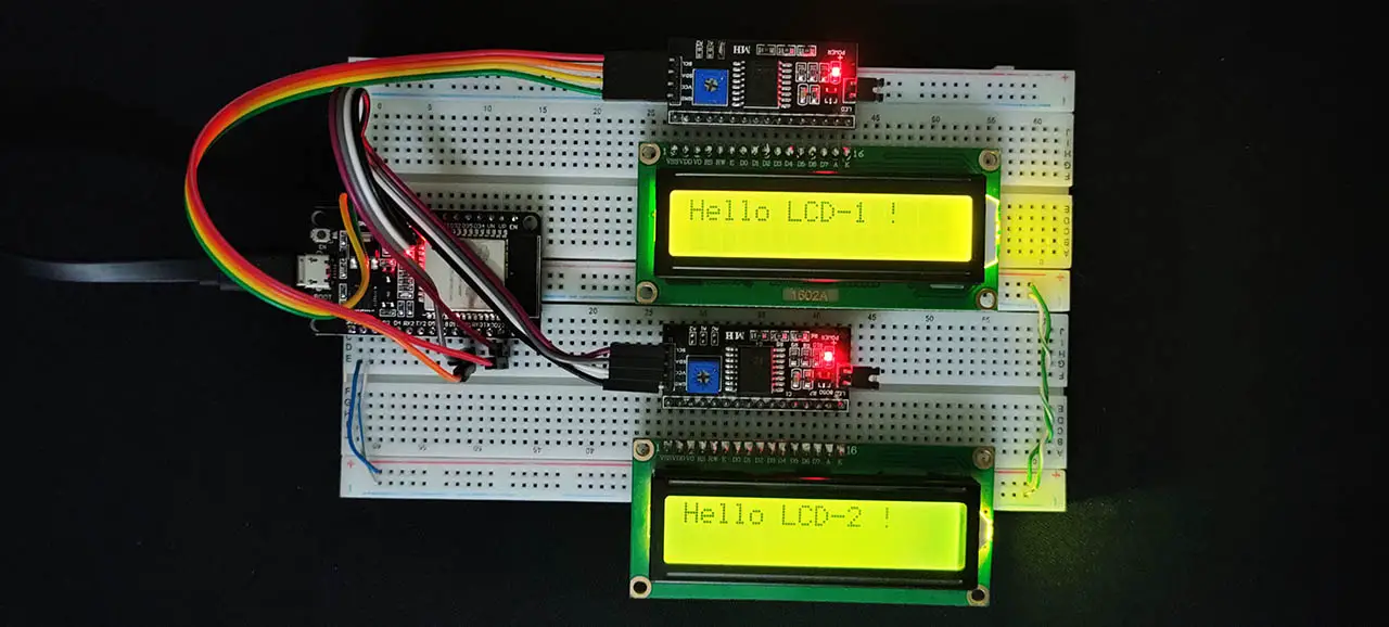
- Print “Hello LCD-1 !” at the home position on LCD1
- Print “Hello LCD-2 !” at the home position on LCD2
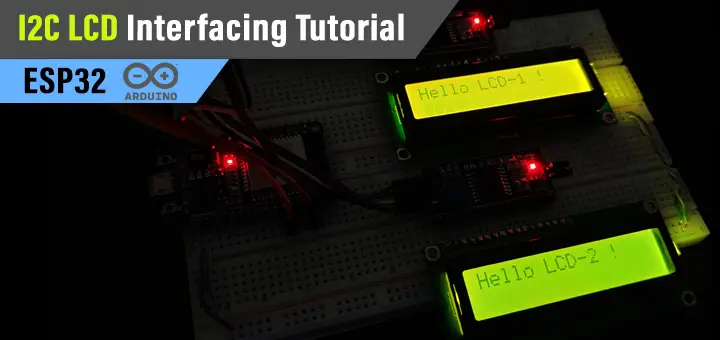
Don’t forget to change the default address for one of the 2 I2C LCD modules as shown earlier in the diagram below (just to recall it).

Connect Multiple I2C LCDs With ESP32 – Arduino Code Example
In this example, we’ll be defining two I2C LCD objects with similar parameters except for the address. The 1st LCD will be @ 0x26 and the 2nd one will be @ 0x27.
We’ll initialize both of them, and write a different message on each LCD to check that addressing is working as it should be. And that’s all about this LAB.
The Full code Listing
|
1 2 3 4 5 6 7 8 9 10 11 12 13 14 15 16 17 18 19 20 21 22 23 24 25 26 27 28 29 30 31 32 33 |
/* * LAB: 21 * Name: ESP32 I2C LCD - Multiple I2C Display Units * Author: Khaled Magdy * For More Info Visit: www.DeepBlueMbedded.com */ #include <Wire.h> #include <LiquidCrystal_I2C.h> LiquidCrystal_I2C I2C_LCD1(0x26, 16, 2); LiquidCrystal_I2C I2C_LCD2(0x27, 16, 2); void setup() { // Initialize The I2C LCDs I2C_LCD1.init(); I2C_LCD2.init(); // Turn ON The Backlight I2C_LCD1.backlight(); I2C_LCD2.backlight(); // Write A Message To LCD1 I2C_LCD1.print("Hello LCD-1 !"); // Write A Message To LCD2 I2C_LCD2.print("Hello LCD-2 !"); } void loop() { // Do Nothing... } |
Choose the board, COM port, hold down the BOOT button, click upload and keep your finger on the BOOT button pressed. When the Arduino IDE starts sending the code, you can release the button and wait for the flashing process to be completed. Now, the ESP32 is flashed with the new firmware.
Here is The Result
ESP32 I2C LCD Applications
ESP32 I2C LCD module can be used in so many applications as we’ll see in future tutorials. I’ll keep updating this series of tutorials by adding more applications and techniques that may help you in your projects. Drop me a comment if you’ve got any questions or suggestions, I’ll be glad to help!
Related Tutorials Based On ESP32 I2C LCD
- ESP32 I2C Tutorial
- ESP32 LM35 Temperature Sensor
- ESP32 Keypad Interfacing
- ESP32 I2C RTC Interfacing
- And More…
Learn More About I2C LCD Module in Depth
- Build Your Own I2C LCD Library (in Embedded-C)
You can also check the ESP32 Course Home Page ???? for more ESP32 tutorials divided into sections based on categories. This may be helpful for you in case of searching for a specific tutorial or application.
Did you find this helpful? If yes, please consider supporting this work and sharing these tutorials!
Stay tuned for the upcoming tutorials and don’t forget to SHARE these tutorials. And consider SUPPORTING this work to keep publishing free content just like this!
| ESP32 Course Home Page ???? | |||||||
| Previous Tutorial | Tutorial 9 | Next Tutorial | |||||

Hi Khaled,
What if you wanted to put a screen on SDA 33, SCL 32? Is it even possible since the default is SDA 21, SCL 22?
I have written some code that uses both of the ESP32 I2C buses, but I need to attach a screen to the second I2C bus.
Serial.begin(9600); inBus.begin(SDA_1, SCL_1, 100000); outBus.begin(SDA_2, SCL_2, 100000);
for (unsigned char j = 0; j < 6; j++) { inMCPs[j].begin(j, &inBus); for (unsigned char k = 0; k < 16; k++) { inMCPs[j].pinMode(k, INPUT); inMCPs[j].pullUp(k, HIGH); } } for (unsigned char j = 0; j < 4; j++) { outMCPs[j].begin(j, &outBus); for (unsigned char k = 0; k < 8; k++) { outMCPs[j].pinMode(k, OUTPUT); outMCPs[j].pullUp(k, HIGH); } } Any chance you can point me in the right direction please.
Hi paul,
I think it’s possible. The problem we have here is the i2c lcd library itself. It uses the default i2c bus.
If I want to do what you’re trying to do, I’d open the i2c lcd library and copy their code into a new library of my own. And modify the code so that the i2c bus is not fixed to the default option only.
I’ll consider this case as an example in some future tutorials about creating custom ESP32 libraries.
I hope this helps
Mr. Khaled excellent explanatory material, thank you so much for teaching so many sharing this knowledge; about 2 I2C displays if one of them was OLED would it be enough to add the appropriate file?
Thank you very much
Jg