In this tutorial, you’ll learn about ESP32 ADC and how to read ESP32 analog input channels (in Arduino IDE). But first of all, you’ll get an introduction to what’s an ADC and how it works in most microcontrollers on a hardware level. Then, we’ll implement an ESP32 ADC analog input read example project, ESP32 ADC error sources, calibration, and much more.
We’ll also summarize the ESP32 ADC Arduino API functions, like analogRead(). Without further ado, let’s get right into it!
| Previous Tutorial | Tutorial 5 | Next Tutorial | |||||
| ESP32 ADC Tutorial (analogRead) – Arduino | |||||||
| ESP32 Course Home Page ???? | |||||||
Table of Contents
- ESP32 ADC Tutorial Requirements
- Analog To Digital Converter (ADC)
- ESP32 ADC Explained
- ESP32 Analog Input (Analog Read in Arduino)
- ESP32 Analog Input Potentiometer LED Dimmer Example
- ESP32 ADC Calibration Example Project (Arduino IDE)
- ESP32 ADC Noise Reduction Example Project
- ESP32 ADC Useful Functions
- ESP32 ADC Concluding Remarks
ESP32 ADC Tutorial Requirements
Prior Knowledge
- Nothing
Software Tools
Hardware Components
You can either get the complete course kit for this series of tutorials using the link down below. Or just refer to the table for the exact components to be used in practical LABs for only this specific tutorial.
Analog To Digital Converter (ADC)
An ADC (Analog to Digital Converter) is an electronic circuit that’s usually integrated into most microcontrollers or comes in as a dedicated IC. We typically use an ADC in order to measure/read the analog voltage from different sources or sensors.
Most parameters and variables are analog in nature and the electronic sensors that we use to capture this information are also analog. Just like temperature, light, pressure, and other sensors are all analog.
The ADC does the inverse operation of a DAC. While an ADC (A/D) converts analog voltage to digital data, the DAC (D/A) converts digital numbers to an analog voltage on the output pin.

This is an in-depth article (tutorial) on ADC, how it works, different types of ADC, error sources, sampling, and much more. Consider checking it out if it’s your first time learning about the ADC.
This tutorial will provide you with more in-depth information about ADC (A/D) converters, types of ADC, how they work, ADC sampling, quantization, ADC errors, and much more.
ESP32 ADC Explained
In this section, I’ll give you an introduction to the hardware capabilities of the ESP32 ADC peripheral, how it works, and what kind of features it has. So you can use it in an efficient way depending on the specific application requirements you have.
ESP32 ADC Pins (ESP32 Analog Input Channels)
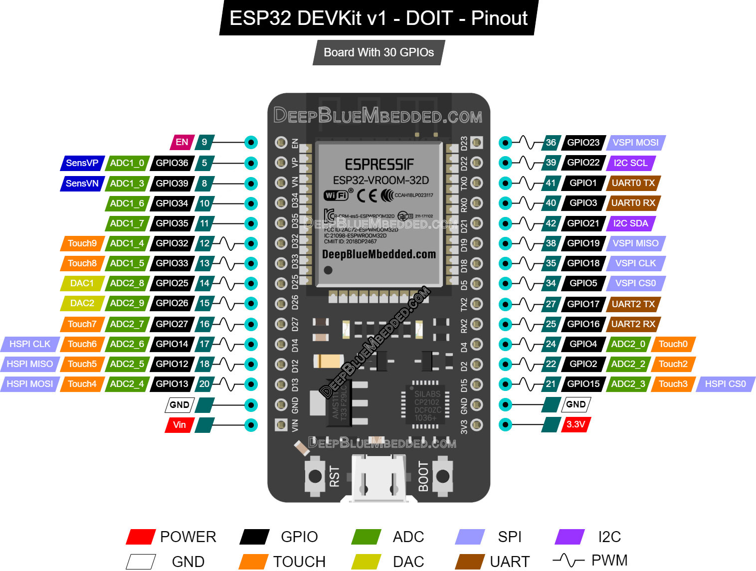
The ESP32 has 2 x 12-Bit SAR (Successive Approximation Register) ADC hardware peripherals that can read 18 different analog input channels.
The ADC firmware driver API supports ADC1 (8 channels, attached to GPIOs 32 – 39), and ADC2 (10 channels, attached to GPIOs 0, 2, 4, 12 – 15, and 25 – 27). However, the usage of ADC2 has some restrictions for the application:
- ADC2 is used by the Wi-Fi driver. Therefore the application can only use ADC2 when the Wi-Fi driver has not been started.
- Some of the ADC2 pins are used as strapping pins (GPIO 0, 2, 15) thus cannot be used freely.
For the exact pinout for our DevKit board’s ADC analog input pins, refer to this ESP32 devkit board pinout.
ESP32 Analog Input Pins:
ESP32 ADC Features
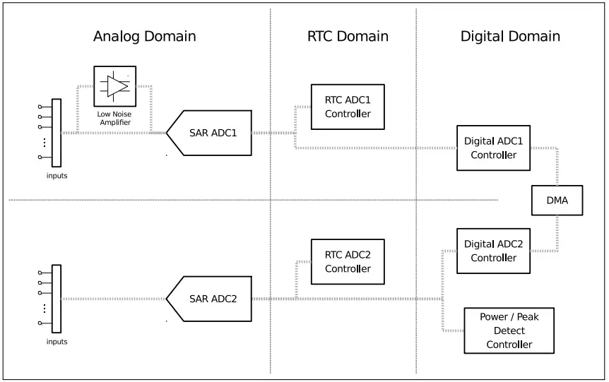
Each one of the ESP32’s ADCs has its own logic controller units. Those control units are shown in the diagram below. They support each ADC to operate in multiple modes to achieve certain design goals (high-performance or low-power consumption).
1- ADC-RTC
ADC-RTC is controlled by the RTC controller and is suitable for low-frequency sampling operations.
2- ADC-DMA
ADC-DMA is controlled by a digital controller and is suitable for high-frequency continuous sampling actions.
Those are the ESP32’s ADC features as stated by its datasheet:
- Two SAR ADCs, with simultaneous sampling and conversion
- Up to five SAR ADC controllers for different purposes (e.g. high performance, low power, or PWDET / PKDET)
- Up to 18 analog input pads
- 12-bit, 11-bit, 10-bit, 9-bit configurable resolution
- DMA support (available on one controller)
- Multiple channel-scanning modes (available on two controllers)
- Operation during deep sleep (available on one controller)
- Controlled by a ULP coprocessor (available on two controllers)
ESP32 ADC Voltage Range
The ESP32 ADC analog input pins are 3.3v tolerant with a peak input voltage of 3.3v. So it’s the maximum voltage a pin can experience under any circumstances. However, you can still do some signal conditioning outside the microcontroller board to accept different input ranges.
But at the ADC analog input pin, the voltage should always be in the range (0 – 3.3v) regardless of what you’re doing externally. Maybe using a voltage divider network to read up to 6.6v inputs (you lose half the resolution by doing this), just to name a use case.
ESP32 ADC Attenuation
The default ADC voltage is for attenuation 0 dB and is listed in the table below. By setting higher attenuation it is possible to read higher voltages. Due to ADC characteristics, the most accurate results are obtained within the “suggested range” shown in the following table.
| SoC | Attenuation (dB) | Suggested Voltage Range (mV) |
| ESP32 | 0 | 100 ~ 950 |
| 2.5 | 100 ~ 1250 | |
| 6 | 150 ~ 1750 | |
| 11 | 150 ~ 2450 | |
| ESP32-S2 | 0 | 0 ~ 750 |
| 2.5 | 0 ~ 1050 | |
| 6 | 0 ~ 1300 | |
| 11 | 0 ~ 2500 |
In the ESP32 Arduino Core ADC driver, you’ll find 2 functions dedicated to setting or changing the ADC analog input channel’s attenuation value. They are listed down below.
|
1 2 3 4 5 6 7 8 9 10 11 |
/* * Set the attenuation for all channels * Default is 11db * */ void analogSetAttenuation(adc_attenuation_t attenuation); /* * Set the attenuation for a particular pin * Default is 11db * */ void analogSetPinAttenuation(uint8_t pin, adc_attenuation_t attenuation); |
- analogSetAttenuation(): Sets the attenuation for all ADC channels
- analogSetPinAttenuation(): Sets the attenuation for a specific analog channel pin
We’ll be mostly using the first function or just ignore this feature altogether. Why? because its default value is -11dB attenuation which already gives us the maximum operating voltage range for the analog inputs (0 – 3.3v).
ESP32 ADC Resolution
The ESP32 ADC has a programmable resolution that can be changed if you want to. By default, it’s a 12-Bit ADC. Which gives you readings in the range (0 – 4095). However, you can change the resolution bits by using the following function from Arduino Core ADC Driver.
|
1 2 3 4 5 6 |
/* * Sets the conversion resolution * Default is 12bit (0 - 4095) * Range is 9 - 12 * */ void analogSetWidth(uint8_t bits); |
The minimum resolution you can get is 9-Bit, at which the ADC conversion range is (0 – 511). You change it if you want, but in most applications, we’ll also leave this feature without changing the default 12-Bit resolution. I had to mention it just in case you need to use it in a particular project or something.

You can use the interactive tool below to set an analog input voltage and see the ESP32 ADC digital output value that corresponds to the analog input voltage. The output equation for the ADC is as follows: ADC Output = ( Analog input voltage / VREF ) x (2n – 1). Where VREF = 3.3v and n is the ADC resolution which is 12bits.
ESP32 ADC Voltage Reference
The ESP32 ADC reference voltage (VREF) varies among different ESP32 chips. By design, the ADC reference voltage is 1100 mV, however, the true reference voltage can range from 1000 mV to 1200 mV amongst different ESP32s.
With that being said, the VREF setting has its own contribution to drifting the ADC readings away from being ideal. There are so many other reasons and sources for ADC errors as we’ll see in the next sections. But (VREF) setting is one of them. The function down below can be used to change the default VREF pin if the device is not already calibrated.
|
1 2 3 4 |
/* * Set pin to use for ADC calibration if the esp is not already calibrated (25, 26 or 27) * */ void analogSetVRefPin(uint8_t pin); |
It’s extremely important to guarantee a stable VREF voltage to get consistent readings with the ADC. We’ll address this shortly after to calibrate the ADC using the Espressif VREF calibration function.
ESP32 ADC Clock
The ESP32 ADC (SAR Type) does the conversion on multiple clock cycles depending on the resolution of the conversion. The faster the clock rate is, the faster the ADC will finish every single A/D conversion process.
You can actually control the FCLK for the ESP32 ADC by changing the clock frequency division factor. Dividing by a larger number will result in a slower clock rate and vice versa. The Arduino Core ADC Driver has a function to change the ESP32 ADC clock rate as shown below.
|
1 2 3 4 5 6 |
/* * Set the divider for the ADC clock. * Default is 1 * Range is 1 - 255 * */ void analogSetClockDiv(uint8_t clockDiv); |
The fastest conversion time for the ADC we can get (when clockDiv = 1). While the slowest option is when (clockDiv = 255).
ESP32 ADC Errors
Generally speaking, there are so many different sources of error when it comes to A/D conversion. Not only in ESP32, but it’s just how ADCs work in most microcontrollers. Usually, you’ll find one or more “AppNotes” from the manufacturer to guide you through calibrating and characterizing the ADC performance to get better results.
1. ESP32 ADC Linearity
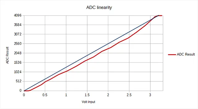
Let’s start with the ESP32 ADC linearity error. An ideal ADC should be linear in response but in practice, you’ll find out non-linearity in the characteristics curve as you can see in the figure below.
2. ESP32 ADC Noise
As stated by Espressif in their documentation, ” The ESP32 ADC can be sensitive to noise leading to large discrepancies in ADC readings. To minimize noise, users may connect a 0.1uF capacitor to the ADC input pad in use. Multi-sampling may also be used to further mitigate the effects of noise”.
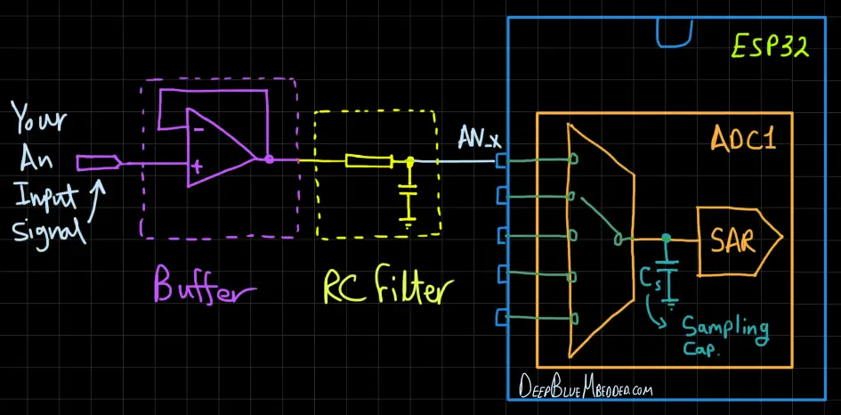
You should be careful before considering to add that capacitor. It’s going to attenuate all the high-frequency components in your analog signal. If you’re measuring a near-DC signal like a temperature sensor or something that’s physically slow to change, then it’s okay. Otherwise, I’d advise against adding any capacitance on the ADC input lines.
Instead, I usually incorporate an active buffering for ADC inputs in most of my designs. However, you should also be careful when doing this. Going cheap on the op-amp will get you more trouble, noise, bandwidth limitation, and end up defeating the purpose of doing such a buffering thing.
A great advantage of having an active buffering (like a voltage follower op-amp config.) is that it reduces the ADC channels cross-coupling while the ADC is switching from channel to channel, the internal ADC’s sampling capacitor will end up picking some measurement noise due to this. Having an active buffer will eliminate this sort of error.
3. ESP32 ADC VREF Offset
As we’ve earlier stated, the VREF is by design around 1.1v but it does vary from chip to chip causing a non-negligible source of error. For this, we’ll be using the calibration method provided by Espressif and see the results. It’s going to be the last LAB in this tutorial, so stick around.
ESP32 ADC Calibration
The ESP32 Arduino Core ADC driver’s API provides functions to correct for differences in measured voltages caused by variation of ADC reference voltages (VREF) between ESP32 chips.
Correcting ADC readings using this API involves characterizing one of the ADCs at a given attenuation to obtain a characteristics curve (ADC-Voltage curve) that takes into account the difference in ADC reference voltage.
The characteristics curve is in the form of y = coeff_a * x + coeff_b and is used to convert ADC readings to voltages in mV. Calculation of the characteristics curve is based on calibration values which can be stored in eFuse or provided by the user.
We’ll be using this function to characterize the ADC parameters.
|
1 2 3 4 5 |
esp_adc_cal_value_t esp_adc_cal_characterize(adc_unit_t adc_num, adc_atten_t atten, adc_bits_width_t bit_width, uint32_t default_vref, esp_adc_cal_characteristics_t *chars); |
Then, we’ll call the ADC read calibrated results functions or use the characteristics to get the results on our own without using the functions below. Especially because they’ll give you the ADC results (in mV) which you might not be interested in.
|
1 2 3 4 5 |
/* Converts Raw ADC Reading To Calibrated Value & Return the results in mV */ uint32_t esp_adc_cal_raw_to_voltage(uint32_t adc_reading, const esp_adc_cal_characteristics_t *chars); /* Reads an ADC channel, calibrate the result, and save it in the voltage pointer (in mV unit) */ esp_err_t esp_adc_cal_get_voltage(adc_channel_t channel, const esp_adc_cal_characteristics_t *chars, uint32_t *voltage); |
ESP32 ADC Sampling Rate
If you’re not familiar with the terminology, the ADC sampling rate is a measure of the ADC speed. In other words, it’s how many times per second can the ADC read an ESP32 analog input channel.
There is no clear statement of how fast the ESP32 ADC can go. Some users have reported getting decent results with a timer interrupt @ up to 10kHz. While in DMA mode, it can get much faster but also didn’t get any exact figures. We’ll be doing our own testing using ESP IDF (not Arduino) in the future and I’ll check this parameter in one way or another.
ESP32 Analog Input (Analog Read in Arduino)
In this section, I’ll give you a step-by-step approach to what to do in order to read any ADC analog input pin.
Step1– Decide on the ESP32 ADC analog input channel that you’re going to use
let it be GPIO 35 for example
|
1 |
int AN_In1 = 35; // GPIO 35 is Now AN Input 1 |
Step2– Call the analog read function to get the raw result
|
1 |
AN_In1_Result = analogRead(AN_In1); |
Optionally you can apply any kind of digital filtering, calibration, or whatever you need before using the results as-is. I’d highly recommend doing a multi-sampling function to average the last-N readings (where N = 4 or more samples).
ESP32 Analog Input Potentiometer LED Dimmer Example
| LAB Number | 9 |
| LAB Name | ESP32 Analog Input Read Potentiometer (LED Dimmer) |
- Define & Attach The PWM GPIO pin
- Configure The PWM Channel (frequency & resolution)
- Read The ADC input channel (Potentiometer)
- Write the ADC_Result to the PWM duty cycle output pin (LED)
Connection Diagram
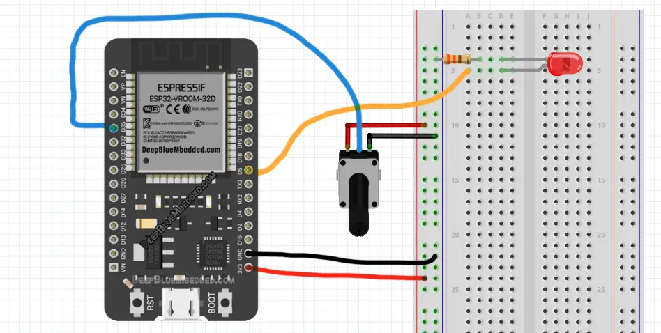
ESP32 Analog Input Read Potentiometer (LED Dimmer Code Example)
The code example down below does the following: We start with defining and attaching The PWM GPIO pin. The pin I’ll be using a PWM pin is GPIO5 in this example.
Then, we’ll be configuring the PWM Channel’s frequency (1kHz) & resolution (12-Bits to be similar to the ADC_Result). And in the main loop() function, I’ll read the ESP32 ADC analog input (potentiometer – GPIO35 pin), and write the result to the PWM duty cycle.
The Full code Listing
|
1 2 3 4 5 6 7 8 9 10 11 12 13 14 15 16 17 18 19 20 21 22 23 24 25 26 27 |
/* * LAB: 9 * Name: ESP32 ADC + Pot LED Dimmer * Author: Khaled Magdy * For More Info Visit: www.DeepBlueMbedded.com */ #define LED_GPIO 5 #define PWM1_Ch 0 #define PWM1_Res 12 #define PWM1_Freq 1000 #define AN_Pot1 35 int AN_Pot1_Result = 0; void setup() { ledcAttachPin(LED_GPIO, PWM1_Ch); ledcSetup(PWM1_Ch, PWM1_Freq, PWM1_Res); } void loop() { AN_Pot1_Result = analogRead(AN_Pot1); ledcWrite(PWM1_Ch, AN_Pot1_Result); delay(1); } |
Choose the board, COM port, hold down the BOOT button, click upload, and keep your finger on the BOOT button pressed. When the Arduino IDE starts sending the code, you can release the button and wait for the flashing process to be completed. Now, the ESP32 is flashed with the new firmware.
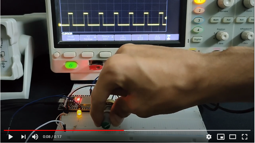
Demo Video For The Result
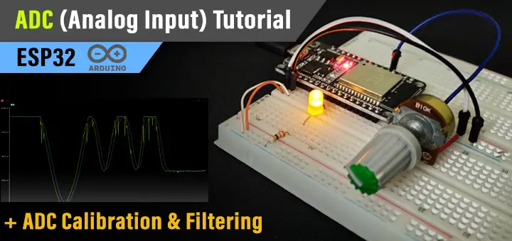
Click The image to watch the demo video on YouTube
ESP32 ADC Calibration Example Project (Arduino IDE)
| LAB Number | 10 |
| LAB Name | ADC Calibration Procedure |
ESP32 ADC Calibration – Code Example
In this example, I’ve used the ADC Calibration functions from Arduino Core ADC APIs. For this LAB, you’ll need a pretty accurate DMM (digital multi-meter). Then, I’ve picked an analog input channel pin (GPIO35).
You’ll have to connect the potentiometer to that analog channel pin and tweak the pot until you get 2v (or any other value). Just make sure the DMM is reading an exact value (2v or any other value).
Now, read the ADC with the analogRead() function without calibration or whatsoever and note down that value. For me, it was 1.85v, while the DMM is reading an exact 2v.
Then, I’ve incorporated the ADC calibration functions in my code as shown below. The result was 1.99v which is very close to the DMM reading. But keep in mind that this calibration procedure has an offset (dead-band) on both ends of the spectrum (in my test that was 0.14v near-zero end and near 3.3v end).
|
1 2 3 4 5 6 7 8 9 10 11 12 13 14 15 16 17 18 19 20 21 22 23 24 25 26 27 28 29 30 31 32 33 34 35 |
/* * LAB: 10 * Name: ESP32 ADC Calibration * Author: Khaled Magdy * For More Info Visit: www.DeepBlueMbedded.com */ #include "esp_adc_cal.h" #define AN_Pot1 35 int AN_Pot1_Result = 0; float Voltage = 0.0; void setup() { Serial.begin(115200); } void loop() { AN_Pot1_Result = analogRead(AN_Pot1); Voltage = readADC_Cal(AN_Pot1_Result); Serial.println(Voltage/1000.0); // Print Voltage (in V) //Serial.println(Voltage); // Print Voltage (in mV) delay(100); } uint32_t readADC_Cal(int ADC_Raw) { esp_adc_cal_characteristics_t adc_chars; esp_adc_cal_characterize(ADC_UNIT_1, ADC_ATTEN_DB_11, ADC_WIDTH_BIT_12, 1100, &adc_chars); return(esp_adc_cal_raw_to_voltage(ADC_Raw, &adc_chars)); } |
ESP32 ADC Noise Reduction Example Project
| LAB Number | 11 |
| LAB Name | ADC Noise Reduction By Multi-Sampling & Moving Average Digital Filtering |
ESP32 ADC Noise Reduction By Multi-Sampling & Moving Average Digital Filtering – Code Example
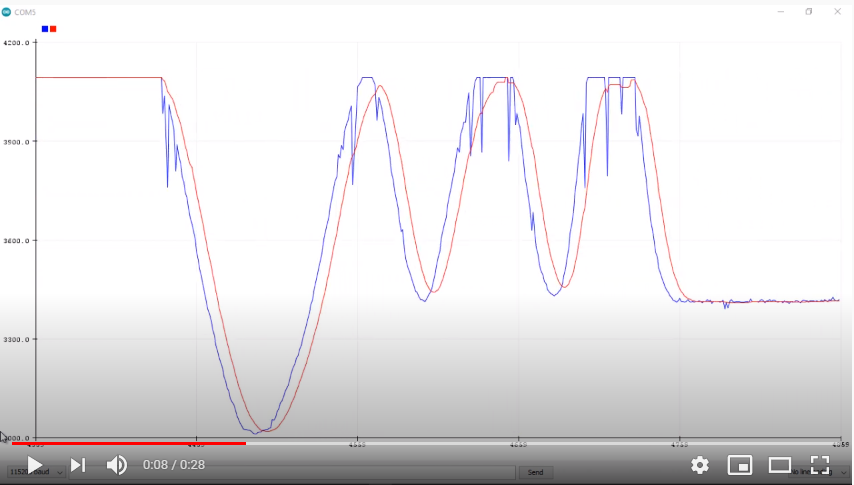
Another type of error that you’ll probably experience is the noise and fluctuations in readings. This can be reduced by placing a small capacitor on the ADC input pin (Hardware solution). Or by applying a simple digital filter like the moving average filter (Software solution). Both will work in the same way but I’d go for the multi-sampling and averaging solution.
This is an example code for doing multi-sampling and averaging for a specific ADC channel. You can change the Filter_Length to whatever you want but note that the larger it gets, the slower the response of the filter gets (it increases the phase lag effect but it gets smoother as it attenuates more frequencies).
|
1 2 3 4 5 6 7 8 9 10 11 12 13 14 15 16 17 18 19 20 21 22 23 24 25 26 27 28 29 30 31 32 33 34 35 36 37 38 39 40 41 42 43 44 45 46 47 48 |
/* * LAB: 11 * Name: ESP32 ADC Multi-Sampling & Moving Average Filter * Author: Khaled Magdy * For More Info Visit: www.DeepBlueMbedded.com */ #include "esp_adc_cal.h" #define AN_Pot1 35 #define FILTER_LEN 15 uint32_t AN_Pot1_Buffer[FILTER_LEN] = {0}; int AN_Pot1_i = 0; int AN_Pot1_Raw = 0; int AN_Pot1_Filtered = 0; void setup() { Serial.begin(115200); } void loop() { AN_Pot1_Raw = analogRead(AN_Pot1); AN_Pot1_Filtered = readADC_Avg(AN_Pot1_Raw); Serial.print(AN_Pot1_Raw); // Print Raw Reading Serial.print(','); // Comma Separator Serial.println(AN_Pot1_Filtered); // Print Filtered Output delay(10); } uint32_t readADC_Avg(int ADC_Raw) { int i = 0; uint32_t Sum = 0; AN_Pot1_Buffer[AN_Pot1_i++] = ADC_Raw; if(AN_Pot1_i == FILTER_LEN) { AN_Pot1_i = 0; } for(i=0; i<FILTER_LEN; i++) { Sum += AN_Pot1_Buffer[i]; } return (Sum/FILTER_LEN); } |
Demo Video For The Result
Click The image to watch the demo video on YouTube
Note that: the blue curve is the Raw ADC Readings, and the red curve is the Filtered ADC Readings.
ESP32 ADC Useful Functions
adcAttachPin(pin): Attach an analog input pin to the ADC
analogRead(pin): Get the ADC Value for the specified pin.
analogSetWidth(bits): Sets the ADC resolution (in bits). The default is 12-bit but the range is 9 to 12.
analogSetAttenuation(attenuation): Set the attenuation for all channels. Default is 11db but possible values are 0db, 2_5db, 6db, and 11db.
analogSetPinAttenuation(pin, attenuation): Set the attenuation for a particular pin.
analogSetClockDiv(clockDiv): Set the divider for the ADC clock.
analogSetVRefPin(pin): Set the pin to be used for ADC calibration if ESP32 is not already calibrated. Possible pins are 25, 26, or 27.
analogReadMilliVolts(pin): Reads an analog channel, converts the raw value to voltage (in mV), and returns that voltage value.
Required Parts For Example LABs
| QTY. | Component | Buy |
| 1 | ESP32 Devkit v1 DOIT Board | Amazon.com – eBay.com – Banggood.com |
| 2 | BreadBoard | Amazon.com – eBay.com – Banggood.com |
| 1 | Resistors Kit | Amazon.com / Amazon.com – eBay.com – Banggood.com |
| 1 | Jumper Wires Pack | Amazon.com / Amazon.com – eBay.com / eBay.com – Banggood.com |
| 1 | LEDs Kit | Amazon.com / Amazon.com – eBay.com – Banggood.com |
| 1 | Potentiometers | Amazon.com / Amazon.com – eBay – Banggood.com |
| 1 | Micro USB Cable | Amazon.com – eBay.com – Banggood.com |
★ Check The Full Course Complete Kit List & LAB Test Equipment Required For Debugging
Download Attachments
You can download all attachment files for this Article/Tutorial (project files, schematics, code, etc..) using the link below. Please consider supporting my work through the various support options listed in the link below. Every small donation helps to keep this website up and running and ultimately supports our community.
ESP32 ADC Concluding Remarks
ESP32 ADC hardware peripheral can be used in many applications as we’ll see in future tutorials. I’ll keep updating this series of tutorials by adding more applications and techniques that may help you in your projects. Drop me a comment if you’ve got any questions or suggestions, I’ll be glad to help!
Related Tutorials Based On ESP32 ADC
- ESP32 Motor Speed Control
- ESP32 LM35 Temperature Sensor Interfacing
- ESP32 LDR Light Sensor Interfacing
- ESP32 Joystick Interfacing
- And More…
Learn More About ADC in General
You can also check the ESP32 Course Home Page ???? for more ESP32 tutorials divided into sections based on categories. This may be helpful for you in case of searching for a specific tutorial or application.

I have a code for counting samples of ADC.I’m attaching the code here.
Code:
#include
#include
#include
const uint16_t samples = 10000;
uint8_t clockDiv =255;
void setup() {
Serial.begin(115200);
adc1_config_width(ADC_WIDTH_BIT_12);
adc1_config_channel_atten(ADC1_CHANNEL_3, ADC_ATTEN_DB_11);
adc_set_clk_div(clockDiv); //doesn’t work
}
void loop() {
const uint16_t samples = 10000;
auto t1 = std::chrono::system_clock::now();
for (uint32_t i=0; i
adc_buf[i]=adc1_get_raw(ADC1_CHANNEL_3);
}
auto t2 = std::chrono::system_clock::now();
std::chrono::duration diff = t2 – t1;
auto ms = std::chrono::duration_cast(diff).count();
//For seeing output if needed
//for (int j=0; j
// Serial.print(adc_buf[j]);Serial.print(” “);
// }
Serial.println();
Serial.printf(“Samples: %u\n”, samples);
Serial.printf(“Duration: %llums\n”, ms);
Serial.printf(“KSPS: %0.4f”, static_cast(samples) / ms);
Serial.println();
}
The problem is that no clock divider is changing the sampling rate .. My device showing about 20ksps.
Although if I change CPU frequency from the ArduinoIDE settings the code showing sampling rate as low as 1ksps .But why does the adc_set_clk_div(clockDiv) not working.Could you kindly look over this problem ?
Hi Samit!
Well, i’ve looked into this while writing this tutorial.
Your procedure for measuring the adc sampling rate is logically correct.
However, the adc read function is a non-blocking routine. Which means, reading the timer before and after that function will not give you the adc conversion time.
There was a function in the adc driver that was a blocking routine which waits until conversion completion then returns. But they’ve removed it for some reason back in 2019 or something.
I know it can be strange a little bit, but the adc function we have is working asynchronously in a non-blocking way.
This shows you that changing the clock div won’t change anything at all. While changing cpu frequency will change the speed it goes from time capture before and after adc read. This is logical too!
Hope this helps.
Kind regards,
Khaled M.
Thanks a lot for your explanation. Yeah it’s look kinda weird . However then could you suggest any other way of measuring the ADC sampling frequency as I need to know and be able to change it’s ADC sampling frequency for my project. Thanks in advance.
I think switching to espressif IDF can help you get more control over the ADC operation. But with a little bit more complex workflow. I’ll be doing this in the future here on my website.
For now, you can search online if you want to take this route!
Also as mentioned ADC-DMA can be used for faster sampling ,could you kindly demonstarate with example how to store ADC values in DMA and read it. Hoping to see more about DMAs. And yes, you have created an excellent website,your contents are so well explained and brought all together in a
so much organized way.Looking forward to seeing lots of videos and projects from here .
Khaled – thanks for this good post. As to the non-blocking ADC read…does using the (I think) lower-level function sequence in Arduino IDE allow for correct time measurement?
startMicro = micros();
adcStart(ADXLpin);
while(adcBusy(ADXLpin)) {;}
ADXLval = adcEnd(ADXLpin);
endMicro = micros();
While researching this topic, I found out that they’ve removed it from the APIs a few years ago. Try to change the ADC’s clock divider and see if it’s getting faster or slower.
If it’s giving you the same conversion time, then the API is not working in the latest Arduino Framework.
Hello Khaled, thanks for the tutorial… I have spent some precious time on trying to correct it… Now i can trust in the values, at least between 140mV ~ 3120mv, as you mentioned there are dead-bands in both spectrum ends, but i am not expecting reading values near to the ends (i guess…).
But, i have some questions:
first, regarding ADC, do i have to implement the ADC calibration functions on every code? The calibrated values is not stored on register for future use? If i always have to implement, do i have to call the funcitions every time i do an analog read, or it can be just in the initialization? Or run time to time? Have you tested not call the function and noticed some deviation with time (that needs to do a recalibration)?
and now regarding the DAC (pwm function). I noticed that you are using some funcionts to configure the PWM output (such configuration as frequency and resolution), i guess this functions which you are using is not provided by espressif, right? And i have checked on the espressif documention and could not find anything that mention i can change the PWM output characteristics (they say that the resolution is 255 and that is it!) so, could you help on this?
Thanks a lot.
Hii anyone please help me, in testing ADCs. After lots of struggle I found good content so you are only my hope please share your contact number.