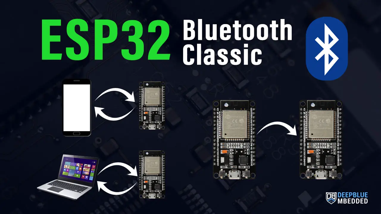
This is a comprehensive guide for ESP32 Bluetooth Classic. You’ll learn how to use ESP32 Bluetooth Classic with Arduino IDE, and how to do all the main operations like (Bluetooth Pairing, Bluetooth Scanner, Send Data in Master Mode, and Receive Data in Slave Mode).
The ESP32 Bluetooth Application Examples That We’ll Create in This Tutorial Are As Follows:
- Android Smartphone –> ESP32 Bluetooth Communication (Rx)
- Android Smartphone <–> ESP32 Bluetooth Communication (Tx/Rx)
- Bluetooth Terminal on PC <–> ESP32 Communication (Tx/Rx)
- ESP32 (Master) –> ESP32 (Slave) Bluetooth Communication
Table of Contents
- ESP32 Bluetooth
- ESP32 Bluetooth Serial Library APIs
- Main Operations For ESP32 Bluetooth
- ESP32 Bluetooth With Android Smartphone (RX)
- ESP32 Bluetooth With Android Smartphone (TX/RX)
- ESP32 Bluetooth With BT Terminal on PC (TX/RX)
- ESP32 To ESP32 Bluetooth Communication
- ESP32 Bluetooth Troubleshooting Common Issues
- Download Attachments
- ESP32 Bluetooth Concluding Remarks
ESP32 Bluetooth
The ESP32 chip is equipped with Bluetooth Classic, Bluetooth Low Energy (BLE), and Wi-Fi. The ESP32 hardware supports up to BLE v4.2 which means it doesn’t support Bluetooth 5.0 currently. Both ESP32 BLE and Bluetooth Classic can be used for connectivity applications but we’ll be focusing in this tutorial on ESP32 Bluetooth Classic. But first, let’s take a quick overview of the ESP32 Bluetooth hardware capabilities.
ESP32 Bluetooth Classic
It’s the easier option for ESP32 Bluetooth communication applications. It works exactly the same as any serial (UART) Bluetooth modules you may have used with Arduino (like HC-05, HC-06, etc). Bluetooth Classic uses the 2.4 GHz ISM (Industrial, Scientific, and Medical) band and has a maximum data rate of 3 Mbps.
It has a range of up to 100 meters in open areas and down to 10m only indoors. Classic Bluetooth devices can connect to other devices using a variety of protocols such as A2DP (Advanced Audio Distribution Profile)
ESP32 BLE (Bluetooth Low Energy)
Bluetooth Low Energy (BLE) is a newer version of Bluetooth technology that was introduced in 2010. BLE uses the same 2.4 GHz ISM band as Classic Bluetooth, but it consumes less power and has a reduced range. It’s mainly used for low-power applications where you need to periodically wake up the device, read some sensor data, send it via BLE, and go back to light sleep.
Using ESP32 BLE is a bit more complicated than Bluetooth classic and we’ll cover it in another tutorial.
ESP32 Bluetooth Classic Vs ESP32 BLE
Here is a quick summarized comparison between ESP32 Bluetooth Classic and BLE.
| Feature | Bluetooth Classic | Bluetooth Low Energy (BLE) |
|---|---|---|
| Data Rate | 1 Mbps for BR 2-3 Mbps for EDR | 500kbps-1Mbps |
| RF Bandwidth | 2.4 GHz ISM band (2400-2483.5 MHz) | 2.4 GHz ISM band (2400-2483.5 MHz) |
| Number of Channels | 79 Channels each of width 1 MHz | 40 Channels each of width 2 MHz |
| Communication Range | The Same (8m up to 100m) | The Same (8m up to 100m) |
| Power Consumption | High (up to 1W) | Low (0.01W up to 0.5W) |
| Device Pairing is Mandatory? | YES | NOT Mandatory |
| Supported Topologies | Peer-to-peer (1:1) | Peer-to-peer (1:1), Star topology (many:1), Broadcast (1:many), and Mesh (many:many) |
| Modulation Technique | GFSK for BR 8-DPSK or π/4-DQPSK for EDR | GFSK |
| Latency | 35ms | 2-16ms (Avg. 9ms) |
ESP32 Bluetooth Serial Library APIs
The ESP32 Bluetooth library that you’ve to include is “BluetoothSerial.h“. This includes the implementation of many useful functions that you’ll definitely need for creating projects with ESP32 Bluetooth. In this section, we’ll discuss the most commonly used functions (APIs) in the ESP32 BluetoothSerial library.
Library Include & Initialization
First of all, you need to include the library, check if Bluetooth is properly enabled, and create an object of the BluetoothSerial.
|
1 2 3 4 5 6 7 8 9 10 11 |
#include "BluetoothSerial.h" #if !defined(CONFIG_BT_ENABLED) || !defined(CONFIG_BLUEDROID_ENABLED) #error Bluetooth is not enabled! Please run `make menuconfig` to and enable it #endif #if !defined(CONFIG_BT_SPP_ENABLED) #error Serial Bluetooth not available or not enabled. It is only available for the ESP32 chip. #endif // Bluetooth Serial Object (Handle) BluetoothSerial SerialBT; |
SerialBluetooth .begin() and .setPin()
To start the Bluetooth module, use the .begin() function in the setup() during initialization. You can give your Bluetooth device any string name you want and/or assign a PIN code for pairing with other devices.
|
1 2 3 4 5 6 |
void setup() { .. SerialBT.begin(device_name); // Bluetooth device name SerialBT.setPin(pin); // If you want to use a PIN .. } |
Send & Receive Data
To send data over Bluetooth, use the .write() function exactly like serial.write() for serial communication.
|
1 |
SerialBT.write(TxBuffer); // Send Data Over Bluetooth |
To read data from Bluetooth received buffer, you’ve to first check if there is any available data in the buffer, then read the data using the .read() function. Here is how to do it and keep adding the incoming data (bytes) into a String buffer array byte-by-byte until a “new line” char (or ‘\n’) is received.
|
1 2 3 4 5 6 7 8 9 10 11 |
String RxBuffer = ""; .. if (SerialBT.available()){ RxByte = SerialBT.read(); if (RxByte != '\n'){ RxBuffer += String(RxByte); } else{ RxBuffer = ""; } } |
ESP32 Get Bluetooth MAC Address
To get the ESP32 Bluetooth device address, we need to call the .getBtAddressString() function. This function takes no argument, and it returns the six bytes Bluetooth address as a string that you can print to the serial monitor. Here is an example of how to do it in Arduino IDE.
|
1 2 3 4 5 6 7 8 9 10 11 12 13 14 15 |
#include "BluetoothSerial.h" BluetoothSerial SerialBT; String MAC_Address; void setup() { Serial.begin(115200); SerialBT.begin("ESP32 Bluetooth"); } void loop() { MAC_Address = SerialBT.getBtAddressString(); Serial.println(MAC_Address.c_str()); delay(500); } |
Bluetooth Master .connect() and .disconnect()
In Bluetooth Master mode, you’ll need to connect to a slave Bluetooth device before data exchange is possible. For this, you’ll need the .connect() function that has two variants to support connecting to a known slave device by its name or MAC address. It’ll return the connection status whether it’s successful or failed.
|
1 2 |
connected = SerialBT.connect(SlaveName); // Use Name connected = SerialBT.connect(SlaveAddress); // Or MAC Address |
To terminate the connection with the slave device, you can use the .disconnect() function which may take up to 10sec for completion.
|
1 2 3 4 |
// Disconnect() may take up to 10 secs max if (SerialBT.disconnect()) { // Disconnected Successfully! } |
ESP32 Bluetooth Events CallBack Function
Instead of polling for various Bluetooth events and keeping the CPU blocked waiting for some data to be received, a connection to be closed, or any other Bluetooth event, we can instead use the CallBack Function to get a notification when any Bluetooth event takes place.
Basically, it’s a function that you define and make the BluetoothSerial driver point to it. When any Bluetooth event occurs, the callback function will be called and executed. Therefore, it’s our responsibility to check which event has occurred and handle it accordingly. Below are the available events that you can check for in the callback function (any event of them will trigger a callback).
|
1 2 3 4 5 6 7 8 9 10 11 12 |
ESP_SPP_INIT_EVT: When SPP mode is initialized ESP_SPP_UNINIT_EVT: When the SPP mode is deinitialized ESP_SPP_DISCOVERY_COMP_EVT: When service discovery is complete ESP_SPP_OPEN_EVT: When an SPP client opens a connection ESP_SPP_CLOSE_EVT: When an SPP connection is closed ESP_SPP_START_EVT: When the SPP server is initialized ESP_SPP_CL_INIT_EVT: When an SPP client initializes a connection ESP_SPP_DATA_IND_EVT: When receiving data through an SPP connection ESP_SPP_CONG_EVT: When congestion status changes on an SPP connection ESP_SPP_WRITE_EVT: When sending data through SPP. ESP_SPP_SRV_OPEN_EVT: When a client connects to the SPP server ESP_SPP_SRV_STOP_EVT: When the SPP server stops |
In order to use this method instead of polling for events, you need to do 2 steps. First of all, define the CallBack event handler function for Bluetooth according to your application. You don’t need to check for and handle all events, only the ones you’re interested in. The second step is to make the BluetoothSerial driver point to the CallBack function that you’ve defined in the first step. Here is an example of how to do it.
|
1 2 3 4 5 6 7 8 9 10 11 12 13 14 15 16 17 18 19 20 21 22 23 24 25 26 27 28 29 |
... // Bluetooth Event Handler CallBack Function Definition void BT_EventHandler(esp_spp_cb_event_t event, esp_spp_cb_param_t *param) { if (event == ESP_SPP_START_EVT) { Serial.println("Initialized SPP"); } else if (event == ESP_SPP_SRV_OPEN_EVT ) { Serial.println("Client connected"); } else if (event == ESP_SPP_CLOSE_EVT ) { Serial.println("Client disconnected"); } else if (event == ESP_SPP_DATA_IND_EVT ) { Serial.println("Data received"); while (SerialBT.available()) { int incoming = SerialBT.read(); Serial.println(incoming); } } } void setup() { ... SerialBT.begin(device_name); SerialBT.setPin(pin); SerialBT.register_callback(BT_EventHandler); // Attach The CallBack Function Definition To SerialBlutooth Events ... } |
There are more APIs that we’ll cover in this tutorial hereafter in the next section. But the APIs shown above are the most commonly used that you need to know well. Because in all Bluetooth applications, we’re going to be using most of them.
Main Operations For ESP32 Bluetooth
In this section, we’ll have a look at different operations for ESP32 Bluetooth Classic and how to perform them in Arduino IDE. I’ll give you a demo example for each application that you can modify as needed before testing.
ESP32 Bluetooth Scanner
The ESP32 Bluetooth Scanner is also called Device Discovery which is a very simple application that runs either Synchronously or Asynchronously and searches for all surrounding Bluetooth devices and report their number, names, and MAC addresses. Then you can choose which device to connect to afterward or keep rescanning in case no device is found.
As stated earlier the ESP32 Bluetooth Scanner can run Synchronously (Blocking) which means it’ll keep searching until completion and the whole application will be stuck until the synchronous function call is executed till completion. It’s not generally a bad thing to do as it may be required in some applications.
In order to perform Bluetooth Scanning for Device Discovery (Synchronously), use the SerialBT.discover(BT_DISCOVER_TIME) function. For Asynchronous scanning, you should use SerialBT.discoverAsync() function instead.
Here is an example code for ESP32 Bluetooth Scanner (Synchronous) in Arduino IDE.
|
1 2 3 4 5 6 7 8 9 10 11 12 13 14 15 16 17 18 19 20 21 22 23 24 25 26 27 28 29 30 31 32 |
#include <BluetoothSerial.h> #if !defined(CONFIG_BT_ENABLED) || !defined(CONFIG_BLUEDROID_ENABLED) #error Bluetooth is not enabled! Please run `make menuconfig` to and enable it #endif #if !defined(CONFIG_BT_SPP_ENABLED) #error Serial Bluetooth not available or not enabled. It is only available for the ESP32 chip. #endif BluetoothSerial SerialBT; #define BT_DISCOVER_TIME 10000 static bool btScanSync = true; void setup() { Serial.begin(115200); SerialBT.begin("ESP32test"); //Bluetooth device name Serial.println("The device started, now you can pair it with bluetooth!"); if (btScanSync) { Serial.println("Starting discover..."); BTScanResults *pResults = SerialBT.discover(BT_DISCOVER_TIME); if (pResults) pResults->dump(&Serial); else Serial.println("Error on BT Scan, no result!"); } } void loop() { delay(100); } |
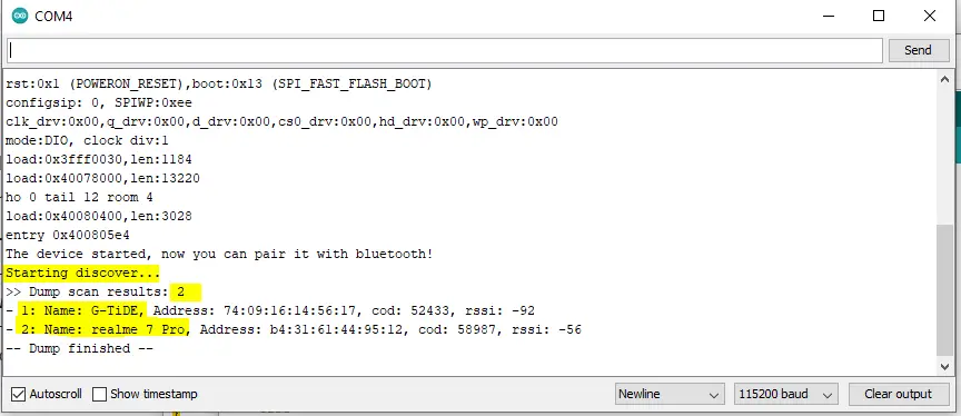
And here is the result on the serial monitor. As you can see, I’ve found 2 Bluetooth devices around which I could confirm using my smartphone.
ESP32 Bluetooth Pairing
Bluetooth Pairing is required in order to establish a connection between the devices on the bridge. Let’s say you’ve got an ESP32 Bluetooth (Master) device and you’d like to send some data to another ESP32 Bluetooth (Slave) device. It’s necessary for the master device to search for the Bluetooth slave device (by Name or MAC address) and do the pairing step using the correct PIN code for that slave device.
We’ll do a practical LAB for this application specifically hereafter in this tutorial but in general, this is what a master device code will look like in order to do Bluetooth pairing with a slave device.
|
1 2 3 4 5 6 7 8 9 10 11 12 13 14 15 16 17 18 19 20 21 22 23 24 25 26 27 28 29 30 31 32 33 34 35 36 37 38 39 40 41 42 43 44 45 46 47 48 49 50 51 52 53 54 55 56 57 58 59 60 61 62 63 64 65 66 67 68 69 70 71 72 73 74 |
#include "BluetoothSerial.h" #define USE_NAME // Comment this to use MAC address instead of a slaveName const char *pin = "1234"; // Change this to reflect the pin expected by the real slave BT device #if !defined(CONFIG_BT_SPP_ENABLED) #error Serial Bluetooth not available or not enabled. It is only available for the ESP32 chip. #endif BluetoothSerial SerialBT; #ifdef USE_NAME String slaveName = "ESP32-BT-Slave"; // Change this to reflect the real name of your slave BT device #else String MACadd = "AA:BB:CC:11:22:33"; // This only for printing uint8_t address[6] = {0xAA, 0xBB, 0xCC, 0x11, 0x22, 0x33}; // Change this to reflect real MAC address of your slave BT device #endif String myName = "ESP32-BT-Master"; void setup() { bool connected; Serial.begin(115200); SerialBT.begin(myName, true); Serial.printf("The device \"%s\" started in master mode, make sure slave BT device is on!\n", myName.c_str()); #ifndef USE_NAME SerialBT.setPin(pin); Serial.println("Using PIN"); #endif // connect(address) is fast (up to 10 secs max), connect(slaveName) is slow (up to 30 secs max) as it needs // to resolve slaveName to address first, but it allows to connect to different devices with the same name. // Set CoreDebugLevel to Info to view devices Bluetooth address and device names #ifdef USE_NAME connected = SerialBT.connect(slaveName); Serial.printf("Connecting to slave BT device named \"%s\"\n", slaveName.c_str()); #else connected = SerialBT.connect(address); Serial.print("Connecting to slave BT device with MAC "); Serial.println(MACadd); #endif if(connected) { Serial.println("Connected Successfully!"); } else { while(!SerialBT.connected(10000)) { Serial.println("Failed to connect. Make sure remote device is available and in range, then restart app."); } } // Disconnect() may take up to 10 secs max if (SerialBT.disconnect()) { Serial.println("Disconnected Successfully!"); } // This would reconnect to the slaveName(will use address, if resolved) or address used with connect(slaveName/address). SerialBT.connect(); if(connected) { Serial.println("Reconnected Successfully!"); } else { while(!SerialBT.connected(10000)) { Serial.println("Failed to reconnect. Make sure remote device is available and in range, then restart app."); } } } void loop() { if (Serial.available()) { SerialBT.write(Serial.read()); } if (SerialBT.available()) { Serial.write(SerialBT.read()); } delay(20); } |
ESP32 Bluetooth Send Data (Master)
To create an ESP32 Bluetooth Master device, you need to handle the searching for available devices, and pairing with the desired slave address, and after a successful connection is established, you can start sending data to the slave drive.
The code for the ESP32 Bluetooth Master device will also be very similar to the example shown above (Bluetooth Pairing Example). You can use it as is or do the needed modifications. It’s going to work seamlessly with a slave device that uses the code example down below in the next section.
ESP32 Bluetooth Receiver (Slave)
To create an ESP32 Bluetooth Receiver (Slave) device, you have to give it a name, a PIN code for pairing, and start the Bluetooth operation. If the master device has successfully paired with the slave device, it’ll start receiving data and processing it accordingly.
We’ll create 4 different applications in the upcoming sections hereafter in this tutorial. But just for your reference, here is a demo example of how an ESP32 Bluetooth Receiver (Slave) device’s code shall look like.
|
1 2 3 4 5 6 7 8 9 10 11 12 13 14 15 16 17 18 19 20 21 22 23 24 25 26 27 28 29 30 |
#include "BluetoothSerial.h" #if !defined(CONFIG_BT_ENABLED) || !defined(CONFIG_BLUEDROID_ENABLED) #error Bluetooth is not enabled! Please run `make menuconfig` to and enable it #endif #if !defined(CONFIG_BT_SPP_ENABLED) #error Serial Bluetooth not available or not enabled. It is only available for the ESP32 chip. #endif const char *pin = "1234"; // Change this to more secure PIN. String device_name = "ESP32-BT-Slave"; BluetoothSerial SerialBT; void setup() { Serial.begin(115200); SerialBT.begin(device_name); //Bluetooth device name Serial.printf("The device with name \"%s\" is started.\nNow you can pair it with Bluetooth!\n", device_name.c_str()); SerialBT.setPin(pin); Serial.println("Using PIN"); } void loop() { if (Serial.available()) { SerialBT.write(Serial.read()); } if (SerialBT.available()) { Serial.write(SerialBT.read()); } delay(20); } |
ESP32 Bluetooth With Android Smartphone (RX)
In this example, we’ll create an ESP32 Bluetooth Receiver (Slave) Device and use Android Smartphone to control it over Bluetooth.
Android Smartphone -> ESP32 Bluetooth (Slave)
To do this practical LAB example, you’ll need to download an Android application from the Play Store. It’s called “Serial Bluetooth Terminal” or any other equivalent application that does the same thing.
The ESP32 Bluetooth Receiver will Turn ON and OFF an LED based on the received string of data that will be sent from the Smartphone over Bluetooth communication.
Wiring
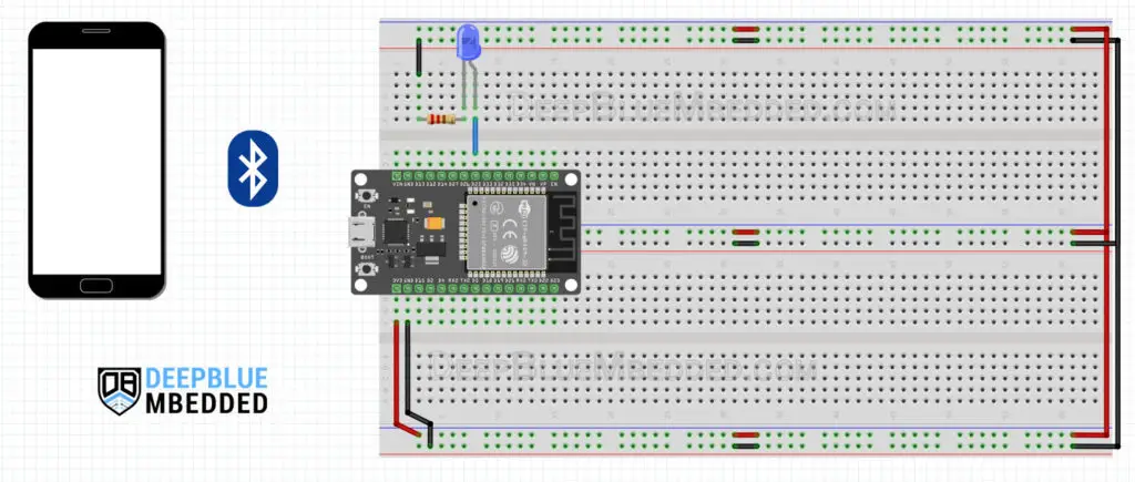
Here is how to hook up the output signal to the LED, nothing more is required for this LAB.
Example Code
Here is the Example code listing for this LAB.
|
1 2 3 4 5 6 7 8 9 10 11 12 13 14 15 16 17 18 19 20 21 22 23 24 25 26 27 28 29 30 31 32 33 34 35 36 37 38 39 40 41 42 43 44 45 46 47 48 49 50 51 52 53 54 55 56 57 58 59 |
/* * LAB Name: Android SmartPhone -> ESP32 Bluetooth (Slave) * Author: Khaled Magdy * DeepBlueMbedded 2023 * For More Info Visit: www.DeepBlueMbedded.com */ #include "BluetoothSerial.h" #if !defined(CONFIG_BT_ENABLED) || !defined(CONFIG_BLUEDROID_ENABLED) #error Bluetooth is not enabled! Please run `make menuconfig` to and enable it #endif #if !defined(CONFIG_BT_SPP_ENABLED) #error Serial Bluetooth not available or not enabled. It is only available for the ESP32 chip. #endif // LED GPIO Pin Definition #define LED_GPIO 25 // Bluetooth Serial Object (Handle) BluetoothSerial SerialBT; // ESP32 Bluetooth (Slave) Device Information const char *pin = "1234"; // Change this to more secure PIN. String device_name = "ESP32-BT-Slave"; // Bluetooth Received Byte & Message Buffer Array String RxBuffer = ""; char RxByte; void setup() { pinMode(LED_GPIO, OUTPUT); Serial.begin(115200); SerialBT.begin(device_name); //Bluetooth device name Serial.printf("The device with name \"%s\" is started.\nNow you can pair it with Bluetooth!\n", device_name.c_str()); SerialBT.setPin(pin); Serial.println("Using PIN"); } void loop() { // Read The Received Bytes & Add Them To Message (RxBuffer) Array if (SerialBT.available()){ RxByte = SerialBT.read(); if (RxByte != '\n'){ RxBuffer += String(RxByte); } else{ RxBuffer = ""; } Serial.write(RxByte); } // Check The Received Message & Update Output LED State if (RxBuffer =="led_on"){ digitalWrite(LED_GPIO, HIGH); } else if (RxBuffer =="led_off"){ digitalWrite(LED_GPIO, LOW); } delay(25); } |
Choose the board, the COM port, hold down the BOOT button, click upload, and keep your finger on the BOOT button pressed. When the Arduino IDE starts sending the code, you can release the button and wait for the flashing process to be completed. Now, the ESP32 is flashed with the new firmware.
Code Explanation
Let’s take a look at the code for this LAB and see how it works step by step.
First of all, include the BluetoothSerial library and check if Bluetooth is properly enabled or not.
|
1 2 3 4 5 6 7 8 |
#include "BluetoothSerial.h" #if !defined(CONFIG_BT_ENABLED) || !defined(CONFIG_BLUEDROID_ENABLED) #error Bluetooth is not enabled! Please run `make menuconfig` to and enable it #endif #if !defined(CONFIG_BT_SPP_ENABLED) #error Serial Bluetooth not available or not enabled. It is only available for the ESP32 chip. #endif |
Create an instance of the BluetoothSerial called SerialBT, and define a GPIO pin for LED output which is going to be GPIO25 pin.
|
1 2 3 4 |
// LED GPIO Pin Definition #define LED_GPIO 25 // Bluetooth Serial Object (Handle) BluetoothSerial SerialBT; |
Set a PIN code for the ESP32 slave device “1234” and a name “ESP32-BT-Slave“. Create a variable “RxByte” to hold the last received byte of data and an array “RxBuffer” to store the incoming data byte by byte.
|
1 2 3 4 5 6 |
// ESP32 Bluetooth (Slave) Device Information const char *pin = "1234"; // Change this to more secure PIN. String device_name = "ESP32-BT-Slave"; // Bluetooth Received Byte & Message Buffer Array String RxBuffer = ""; char RxByte; |
setup()
in the setup() function, set the LED pin to output
|
1 |
pinMode(LED_GPIO, OUTPUT); |
Start serial communication for monitoring & debugging
|
1 |
Serial.begin(115200); |
Start the Bluetooth device with the given name and PIN code.
|
1 2 3 4 |
SerialBT.begin(device_name); //Bluetooth device name Serial.printf("The device with name \"%s\" is started.\nNow you can pair it with Bluetooth!\n", device_name.c_str()); SerialBT.setPin(pin); Serial.println("Using PIN"); |
loop()
In the loop() function, read the incoming data bytes and push them to the RxBuffer array.
|
1 2 3 4 5 6 7 8 9 10 11 |
// Read The Received Bytes & Add Them To Message (RxBuffer) Array if (SerialBT.available()){ RxByte = SerialBT.read(); if (RxByte != '\n'){ RxBuffer += String(RxByte); } else{ RxBuffer = ""; } Serial.write(RxByte); } |
Then check the received message buffer (RxBuffer) array, if it’s “led_on” turn the LED ON, else if it was “led_off” turn the LED OFF. Otherwise, don’t take any action. And keep repeating.
|
1 2 3 4 5 6 7 |
// Check The Received Message & Update Output LED State if (RxBuffer =="led_on"){ digitalWrite(LED_GPIO, HIGH); } else if (RxBuffer =="led_off"){ digitalWrite(LED_GPIO, LOW); } |
Testing Results
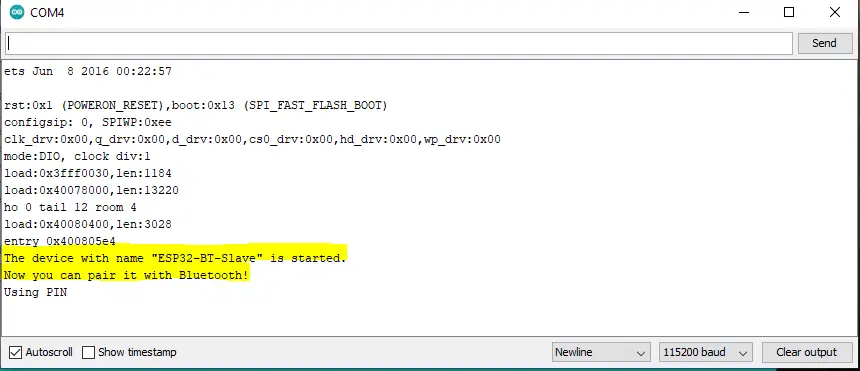
After flashing the code to your ESP32 board, you should get a message like this.
Here is a demo video for the testing result and how to pair & connect your smartphone to the ESP32 Bluetooth device.
ESP32 Bluetooth With Android Smartphone (TX/RX)
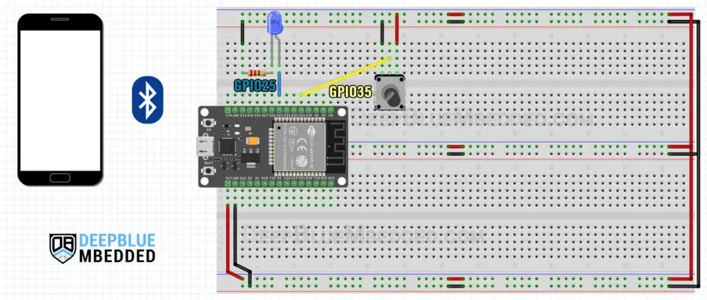
In this example, we’ll exchange data between Android Smartphone serial Bluetooth Terminal and ESP32 Bluetooth Classic. The Smartphone will send led_on and led_off commands to the ESP32. And the ESP32 will receive the commands, control the LED accordingly, read the ADC channel of the potentiometer, and send the RAW ADC reading to the Smartphone over Bluetooth communication.
Android Smartphone <-> ESP32 Bluetooth
Exchange Data With ESP32 Bluetooth & Android Smartphone. The ESP32 Bluetooth device will receive and send data over Bluetooth in this example.
We’ll use a timer interrupt to generate a periodic event at which we’ll read the ADC and send its raw value over Bluetooth. The timer interrupt will be configured to trigger every 100ms. It’s highly recommended that you check out both the ESP32 ADC and ESP32 Timer tutorials in order to get a better understanding of what we’ll implement hereafter in this example.
This article will give more in-depth information about ESP32 Timers and how to properly set the desired timer interrupt interval for ESP32 applications and all the calculations that you’d go through to achieve your design goals.
This article will give more in-depth information about ESP32 ADC and how to read analog inputs, ADC Errors, ADC Calibration, and many more detailed topics.
Wiring
Here is how to hook up the output LED and the Potentiometer.
Example Code
Here is the full code listing for this LAB example.
|
1 2 3 4 5 6 7 8 9 10 11 12 13 14 15 16 17 18 19 20 21 22 23 24 25 26 27 28 29 30 31 32 33 34 35 36 37 38 39 40 41 42 43 44 45 46 47 48 49 50 51 52 53 54 55 56 57 58 59 60 61 62 63 64 65 66 67 68 69 70 71 72 73 74 75 76 77 |
/* * LAB Name: Exchange Data Over Bluetooth * Android SmartPhone <-> ESP32 Bluetooth * Laptop Serial BT <-> ESP32 Bluetooth * Author: Khaled Magdy * DeepBlueMbedded 2023 * For More Info Visit: www.DeepBlueMbedded.com */ #include "BluetoothSerial.h" #if !defined(CONFIG_BT_ENABLED) || !defined(CONFIG_BLUEDROID_ENABLED) #error Bluetooth is not enabled! Please run `make menuconfig` to and enable it #endif #if !defined(CONFIG_BT_SPP_ENABLED) #error Serial Bluetooth not available or not enabled. It is only available for the ESP32 chip. #endif // LED GPIO Pin Definition #define LED_GPIO 25 // Potentiometer Analog Channel GPIO Pin #define AN_Pot 35 // Bluetooth Serial Object (Handle) BluetoothSerial SerialBT; // Timer0 configuration Handle hw_timer_t *Timer0_Cfg = NULL; // ESP32 Bluetooth (Slave) Device Information const char *pin = "1234"; // Change this to more secure PIN. String device_name = "ESP32-BT-Slave"; // Bluetooth Received Byte & Message Buffer Array String RxBuffer = ""; char RxByte; // Timer0 ISR Handler Function (Configured To Execute Every 100ms) void IRAM_ATTR Timer0_ISR() { // Read The Potentiometer ADC Channel & Send Raw Data Over Bluetooth SerialBT.println(analogRead(AN_Pot)); } void setup() { pinMode(LED_GPIO, OUTPUT); Serial.begin(115200); SerialBT.begin(device_name); //Bluetooth device name Serial.printf("The device with name \"%s\" is started.\nNow you can pair it with Bluetooth!\n", device_name.c_str()); SerialBT.setPin(pin); Serial.println("Using PIN"); // Configure Timer0 Interrupt (Every 100mS) Timer0_Cfg = timerBegin(0, 80, true); timerAttachInterrupt(Timer0_Cfg, &Timer0_ISR, true); timerAlarmWrite(Timer0_Cfg, 100000, true); timerAlarmEnable(Timer0_Cfg); } void loop() { // Read The Received Bytes & Add Them To Message (RxBuffer) Array if (SerialBT.available()){ RxByte = SerialBT.read(); if (RxByte != '\n'){ RxBuffer += String(RxByte); } else{ RxBuffer = ""; } Serial.write(RxByte); } // Check The Received Message & Update Output LED State if (RxBuffer =="led_on"){ digitalWrite(LED_GPIO, HIGH); } else if (RxBuffer =="led_off"){ digitalWrite(LED_GPIO, LOW); } delay(25); } |
Code Explanation
The code is very similar to the previous example except for the following parts.
Configuring Timer0 to trigger an interrupt periodically every 100ms in the setup() function.
|
1 2 3 4 5 |
// Configure Timer0 Interrupt (Every 100mS) Timer0_Cfg = timerBegin(0, 80, true); timerAttachInterrupt(Timer0_Cfg, &Timer0_ISR, true); timerAlarmWrite(Timer0_Cfg, 100000, true); timerAlarmEnable(Timer0_Cfg); |
Define the Timer0 ISR (interrupt service routine) handler function in which we’ll read the ADC channel for the potentiometer and send its value over Bluetooth.
|
1 2 3 4 5 6 |
// Timer0 ISR Handler Function (Configured To Execute Every 100ms) void IRAM_ATTR Timer0_ISR() { // Read The Potentiometer ADC Channel & Send Raw Data Over Bluetooth SerialBT.println(analogRead(AN_Pot)); } |
And that’s all, the loop() function will remain the same. It’s handling the Bluetooth data reception and processing, while the Bluetooth data transmission is handled in the Timer0 ISR which executes every 100ms.
Testing Results
Here is a demo video for the testing result and how to pair & connect your smartphone to the ESP32 Bluetooth device. And how to set Macro functions for the Buttons in the Android Bluetooth Terminal application. Note that Bluetooth data transmission and reception are happening simultaneously on the ESP32.
ESP32 Bluetooth With BT Terminal on PC (TX/RX)
In this example, we’ll exchange data with ESP32 Bluetooth and a computer (or Laptop). If your PC (Laptop) supports Bluetooth communication, you can proceed with this example LAB after downloading the required application from Microsoft Store. It’s called “Bluetooth Serial Terminal”, and you can absolutely use any other application that does the same job.
PC (Laptop) Bluetooth <-> ESP32 Bluetooth
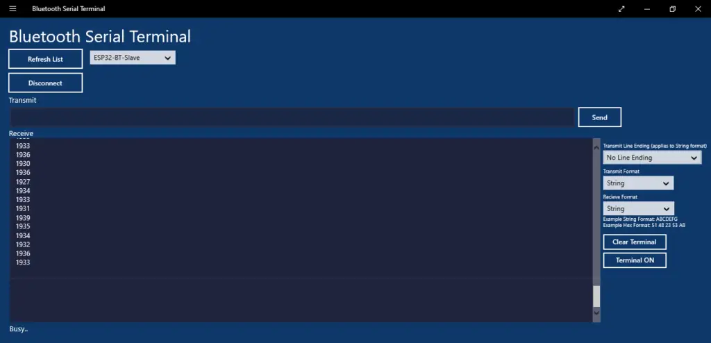
Using “Bluetooth Serial Terminal” on my Laptop, I could also connect to the ESP32 Bluetooth device after pairing. I managed to send led_on and led_off commands while receiving the ADC readings exactly like the previous LAB example with the Android smartphone.
The ESP32 code is exactly the same as the previous example as well as the wiring and everything else.
Here is how the Bluetooth Serial Terminal interface looks like.
ESP32 To ESP32 Bluetooth Communication
The last example LAB for this tutorial is to make 2 ESP32 boards communicate with each other over Bluetooth classic. The ESP32 Bluetooth Master device will send the ADC reading of a potentiometer to control the brightness of an LED at the ESP32 Bluetooth Receiver (slave) side.
ESP32 Bluetooth (Master) -> ESP32 Bluetooth (Slave)
The ESP32 Bluetooth Master Device
Will search for the slave device and pair with it, read a potentiometer with ADC, and periodically send its value over Bluetooth to the slave device.
The ESP32 Bluetooth Receiver (Slave) Device
Will read the incoming Bluetooth data and convert it from string form to integer and use it as a duty cycle to control the PWM output on the LED GPIO pin for brightness control.
Wiring
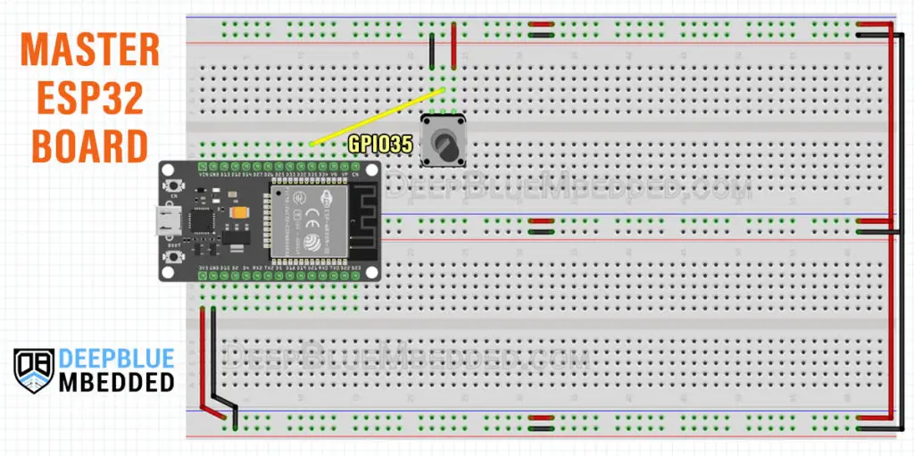
Here is how to hook up the potentiometer (Master ESP32 Board)
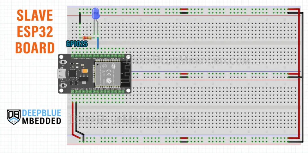
Here is how to hook up the LED output (Slave ESP32 Board)
Example Code (Master ESP32)
Here is the code that you need to flash to the Master ESP32 Board.
|
1 2 3 4 5 6 7 8 9 10 11 12 13 14 15 16 17 18 19 20 21 22 23 24 25 26 27 28 29 30 31 32 33 34 35 36 37 38 39 40 41 42 43 44 45 46 47 48 49 50 51 52 53 54 55 56 57 58 59 60 |
/* * LAB Name: ESP32->ESP32 Bluetooth Communication (MASTER CODE) * [ MASTER CODE ] * Author: Khaled Magdy * DeepBlueMbedded 2023 * For More Info Visit: www.DeepBlueMbedded.com */ #include "BluetoothSerial.h" #if !defined(CONFIG_BT_SPP_ENABLED) #error Serial Bluetooth not available or not enabled. It is only available for the ESP32 chip. #endif // Potentiometer Analog Channel GPIO Pin #define AN_Pot 35 BluetoothSerial SerialBT; const char *pin = "1234"; // Change this to reflect the pin expected by the real slave BT device String slaveName = "ESP32-BT-Slave"; // Change this to reflect the real name of your slave BT device String myName = "ESP32-BT-Master"; void setup() { bool connected; Serial.begin(115200); SerialBT.begin(myName, true); Serial.printf("The device \"%s\" started in master mode, make sure slave BT device is on!\n", myName.c_str()); SerialBT.setPin(pin); Serial.println("Using PIN"); // connect(address) is fast (up to 10 secs max), connect(slaveName) is slow (up to 30 secs max) as it needs // to resolve slaveName to address first, but it allows to connect to different devices with the same name. // Set CoreDebugLevel to Info to view devices Bluetooth address and device names connected = SerialBT.connect(slaveName); Serial.printf("Connecting to slave BT device named \"%s\"\n", slaveName.c_str()); if(connected) { Serial.println("Connected Successfully!"); } else { while(!SerialBT.connected(10000)) { Serial.println("Failed to connect. Make sure remote device is available and in range, then restart app."); } } // Disconnect() may take up to 10 secs max if (SerialBT.disconnect()) { Serial.println("Disconnected Successfully!"); } // This would reconnect to the slaveName(will use address, if resolved) or address used with connect(slaveName/address). SerialBT.connect(); if(connected) { Serial.println("Reconnected Successfully!"); } else { while(!SerialBT.connected(10000)) { Serial.println("Failed to reconnect. Make sure remote device is available and in range, then restart app."); } } } void loop() { // Read The ADC Channel & Send Raw Readings Values Over Bluetooth SerialBT.println(String(analogRead(AN_Pot))); delay(10); } |
Example Code (Slave ESP32)
Here is the Slave ESP32 code.
|
1 2 3 4 5 6 7 8 9 10 11 12 13 14 15 16 17 18 19 20 21 22 23 24 25 26 27 28 29 30 31 32 33 34 35 36 37 38 39 40 41 42 43 44 45 46 47 48 49 50 51 52 53 54 55 56 57 58 59 60 61 62 63 64 65 |
/* * LAB Name: ESP32->ESP32 Bluetooth Communication (SLAVE CODE) * [ SLAVE CODE ] * Author: Khaled Magdy * DeepBlueMbedded 2023 * For More Info Visit: www.DeepBlueMbedded.com */ #include "BluetoothSerial.h" #if !defined(CONFIG_BT_ENABLED) || !defined(CONFIG_BLUEDROID_ENABLED) #error Bluetooth is not enabled! Please run `make menuconfig` to and enable it #endif #if !defined(CONFIG_BT_SPP_ENABLED) #error Serial Bluetooth not available or not enabled. It is only available for the ESP32 chip. #endif // LED GPIO Pin & PWM Definitions #define LED_GPIO 5 #define PWM1_Ch 0 #define PWM1_Res 12 #define PWM1_Freq 1000 int LED_DutyCycle = 0; // Bluetooth Serial Object (Handle) BluetoothSerial SerialBT; // ESP32 Bluetooth (Slave) Device Information const char *pin = "1234"; // Change this to more secure PIN. String device_name = "ESP32-BT-Slave"; // Bluetooth Received Byte & Message Buffer Array String RxBuffer = ""; char RxByte; void setup() { ledcAttachPin(LED_GPIO, PWM1_Ch); ledcSetup(PWM1_Ch, PWM1_Freq, PWM1_Res); Serial.begin(115200); SerialBT.begin(device_name); //Bluetooth device name Serial.printf("The device with name \"%s\" is started.\nNow you can pair it with Bluetooth!\n", device_name.c_str()); SerialBT.setPin(pin); Serial.println("Using PIN"); } void loop() { // Read The Received Bytes & Add Them To Message (RxBuffer) Array if (SerialBT.available()){ RxByte = SerialBT.read(); if (RxByte != '\n'){ RxBuffer += String(RxByte); } else{ RxBuffer = ""; } } LED_DutyCycle = RxBuffer.toInt(); Serial.println(RxBuffer); if(LED_DutyCycle > 10 && LED_DutyCycle < 4095) { ledcWrite(PWM1_Ch, RxBuffer.toInt()); } delay(1); } |
Testing Results
And this is a demo video for the testing results of this LAB example.
ESP32 Bluetooth Master: Read the potentiometer ADC raw value, convert it to a string, and send it to the ESP32 Bluetooth slave board.
ESP32 Bluetooth Slave: Receive the incoming ADC value over Bluetooth and use it to control LED Brightness (PWM DutyCycle).
Please be advised that sending the ADC raw values only as strings is not guaranteed to be picked up right every single time by the slave (receiver) ESP32 device. Better implementations should include error detection and correction techniques with some string manipulations in order to make sure we’re picking up the correct values of the incoming data, otherwise, the incoming data must be neglected. Which we’ll be doing in future tutorials of course.
ESP32 Bluetooth Troubleshooting Common Issues
Here are some of the most common issues that you’d run into during testing the examples provided here in this ESP32 Bluetooth Classic tutorial and how to troubleshoot and solve most of those common issues.
1. A fatal error occurred: “Failed to connect to ESP32: Timed out… Connecting…”
This is a very common ESP32 error that pops up in the Arduino IDE console window during the code-uploading process. Just make sure that you hold the BOOT button on the ESP32 board before clicking the UPLOAD button in the IDE. When it starts connecting to the board, release the BOOT button and the flashing process will continue. On some boards, I’ve noticed that you need to hold the BOOT button for a couple of seconds, then release it, then hold it again for another couple of seconds, then release it, and the flashing process will start normally.
Wait for the “Done Uploading” notification message, and then click the EN button to restart the ESP32 microcontroller in order to execute the newly flashed software and you’re good to go.
2. Error: “Brownout detector was triggered”
This issue is very common when you deal with ESP32 Bluetooth or Wi-Fi as your board needs to draw more current than usual. If your supply source or USB cable is not coping with the current demand, the board will go into Brownout detection and keeps resetting. Major reasons behind the ESP32 Brownout Detector Triggered Error include:
- Poor Power Supply
- Bad Quality USB Power Cable
- Too long USB Cable is being used for power
- Using USB Extender Cable of Poor Quality
- The host USB port has limited output current capability
Any of the reasons above can cause your ESP32 board to detect a brownout condition and keeps resetting. I was using a USB extender cable and it was the reason behind this issue, once replaced with better quality USB power cable, the issue was resolved.
3. Arduino IDE Serial Monitor Blank or Printing Garbage
Make sure that you’ve reset your board by clicking the EN button on the ESP32 board after a new firmware (sketch) is uploaded. And also make sure that the serial port baud rate in Arduino IDE serial monitor matches the serial.begin() baud rate in your code.
4. COM Port Not Found or Not Available
Check the device manager while the ESP32 board is connected. You should find the USB-UART bridge chip (CP210x) as shown below. If you didn’t find it, then it may be a driver issue. Try unplugging the ESP32 board and re-plug it into another USB port on your host machine. If it didn’t also recognize it and enumerate the device, then you’ll need to manually install the drivers for the USB-UART bridge chip.

You can find the CP210x drivers here on Silicon Labs website.
Parts List
Here is the full components list for all parts that you’d need in order to perform the practical LABs mentioned here in this article and for the whole ESP32 series of tutorials found here on DeepBlueMbedded. Please, note that those are affiliate links and we’ll receive a small commission on your purchase at no additional cost to you, and it’d definitely support our work.
Download Attachments
You can download all attachment files for this Article/Tutorial (project files, schematics, code, etc..) using the link below. Please consider supporting my work through the various support options listed in the link down below. Every small donation helps to keep this website up and running and ultimately supports our community.
ESP32 Bluetooth Concluding Remarks
To conclude this tutorial, we’ve learned everything about ESP32 Bluetooth Classic and its most common library APIs. We’ve managed to establish a two-way connection between ESP32 Bluetooth and an Android smartphone, the same for PC (Laptop) With ESP32, and finally ESP32 to ESP32 Bluetooth communication.
Try the given examples in this tutorial on your own, make your customizations and changes, and let me know if you need help with your projects. Stay tuned for the upcoming tutorials and don’t forget to check out the full ESP32 Tutorials Page, and read the recommended articles down below.
This article will give more in-depth information about ESP32 ADC and how to read analog inputs, ADC Errors, ADC Calibration, and many more detailed topics.
This article will give more in-depth information about ESP32 Timers and how to properly set the desired timer interrupt interval for ESP32 applications and all the calculations that you’d go through to achieve your design goals.

Hello Kaled,
Thanks you for your tuto !
Can you help me with this pb?
****************************************************************
I use IDE 2.3.2 With an WROMM32 Espressif Module .
Library is :
Alternative pour BluetoothSerial.h: [BluetoothSerial@2.0.0]
****************************************************************
“Sketch between ESP Slave and Smartphone”.
My problem is with that before pairing, The ESP don’t asks for a PIN.
The Smartphone connects it automatically.
Is there a way to do this ?
In fact i would eventually display a PIN code on a screen of an ESP32 TTGO Oled
And this PIN would be necessary to connect in BT With the module.
Thanks for your answer….
Alain