| Previous Tutorial | Tutorial 7 | Next Tutorial | |||||
| ESP32 LCD Display 16×2 Without I2C – Arduino | |||||||
| ESP32 Course Home Page ???? | |||||||
In this tutorial, you’ll learn how to interface ESP32 with an LCD display 16×2 without I2C. It can be useful in some projects, however, it’s not very common, due to the GPIO pins it does consume. But it’s going to be a good starting point if you’re new to Alphanumeric LCDs in general or just want to use the generic Arduino LiquidCrystal display library.
Without further ado, let’s get right into it!
[toc]
Requirements For This Tutorial
Prior Knowledge
- Nothing
Software Tools
Hardware Components
You can either get the complete course kit for this series of tutorials using the link down below. Or just refer to the table for the exact components to be used in practical LABs for only this specific tutorial.
Interfacing LCD Display 16×2
(Without I2C Module)
Alphanumeric LCD 16×2 display units are the most common and easiest solutions to get some data out of your microcontroller to the world to visually see. It’s a very cheap, easy to use, and reliable option to display strings of text/numbers to your system’s users.
The only downside to using the bare 16×2 LCD display is that it requires 6 dedicated GPIO pins of your microcontroller. In the case of our ESP32, it can be really annoying to lose 6 GPIO pins for adding only 1 LCD module to the project. However, in some projects, it can be a good option in case you don’t need the extra GPIO pins anyway.
(With I2C Module)
The second most commonly preferred option is by using the I2C module with your LCD. This will reduce the GPIO pins requirement down to only 2 pins (the I2C pins SDA & SCL). Not only that, actually the 2 pins of that I2C bus can still access so many other I2C devices on the exact same bus.
You can end up having maybe 5 LCDs connected to your microcontroller using only 2 pins If you’re using that I2C module. But it’s the topic of the next tutorial. For this tutorial, we’ll be doing bare LCD interfacing in a classic way without an I2C IO expansion module.
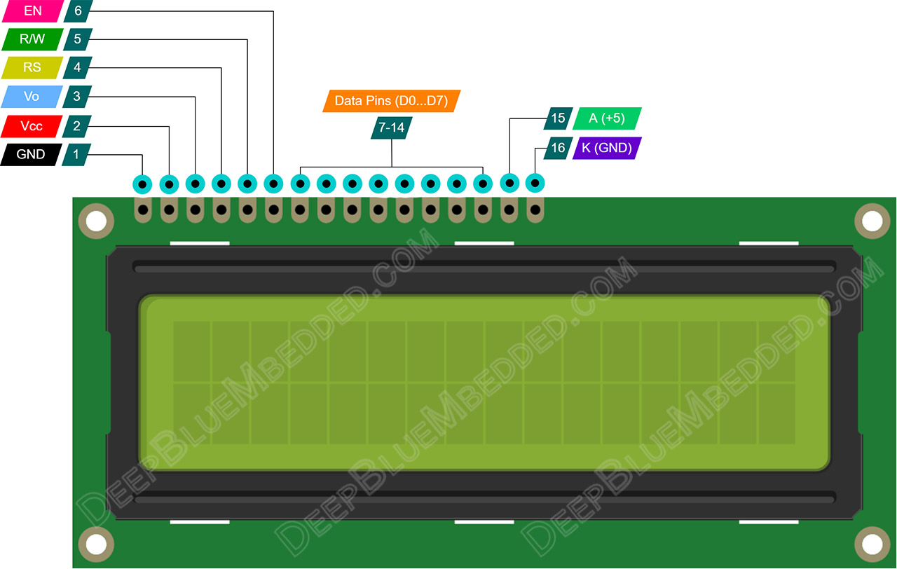
16×2 Character LCD Pinout
This is the pinout for a typical LCD 16×2 display unit. It’s got 8 data lines (you can use only 4 of them or all of the 8). And remember that it needs to be powered from a +5v source despite the fact that our ESP32 is a 3.3v microcontroller device. This requirement is only for the power supply pins, not the data lines.
16×2 Character LCD Modes of Operation
There are two ways to interface the LCD diver (controller) IC. You can use the full bus width (8-Bits) for data or alternatively you can use a 4-Bit interface for a reduced pin count needed to control the LCD. Specifically low pin count MCUs need to operate in the 4-Bit mode. And it’s the case for our ESP32 which has limited resources in terms of GPIO pin count.
So, for this tutorial, we’ll be using ESP32 with LCD 16×2 display in 4-Bit data mode.
The differences between 8-Bit mode and 4-Bit mode are that in the 8-Bit mode you’re operating the LCD at the full speed. While in 4-Bit mode, you send each data byte or command in two consecutive cycles instead of one. The other difference is the initialization routine steps. This is detailed in the full LCD article linked below.
Learn How LCD 16×2 Works In-Depth
If you’re interested in learning more about the LCD display, how it works, how does the LCD driver IC work (the circular black thing on the back), its internal registers, and more. Then, you should check out this tutorial linked down below.
In that tutorial, we’ll be scrolling through the LCD driver datasheet, learning how it works, how to write a driver firmware library for it, and build our own library in Embedded-C with PIC microcontrollers from scratch and test it out in a couple of LABs.
It ‘g going to be a good read if you’re interested in that topic. Let’s now get back to our ESP32 LCD tutorial.
ESP32 LCD 16×2 Without I2C
In this section, I’ll give you a brief description of the LiquidCrystal library that we’ll be using in this tutorial. And it’s basic API functions to initialize and write some text on any LCD. We’ll be using the generic LiquidCrystal library (not the I2C version) which is similar to any other Arduino LCD example code you’ve seen online.
Arduino Core LiquidCrystal Library
The Arduino LiquidCrystal library gives you all the functionalities that you’d need from an LCD driver and it’s very easy to use in your projects. Here are the exact steps you need to follow in order to initialize and write to an LCD in your project code (in Arduino IDE).
Step1– You need to include the liquid crystal library by adding this line of code
|
1 |
#include <LiquidCrystal.h> |
Step2– Create an LCD object. In which you’ll define the GPIO pins to be used for the various LCD signals (6 pins). This is done in code as shown below
|
1 2 |
// Create An LCD Object. Signals: [ RS, EN, D4, D5, D6, D7 ] LiquidCrystal My_LCD(13, 12, 14, 27, 26, 25); |
Step3– Now, you need to initialize the LCD in the Setup function, and it’s better to clear the display to make sure there are no random characters on the visible display. In this step, you also define the number of rows and columns for your display. There are many versions of this LCD display not only 16×2, there are 16×4, 20×4, and maybe others.
|
1 2 3 4 5 6 7 |
void setup() { // Initialize The LCD. Parameters: [ Columns, Rows ] My_LCD.begin(16, 2); // Clears The LCD Display My_LCD.clear(); } |
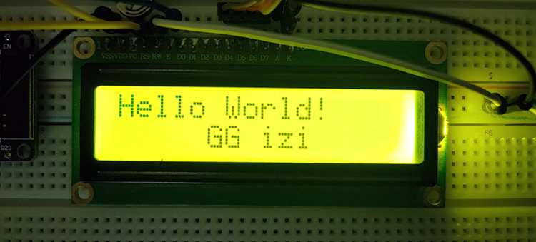
Step4– Now, our LCD is properly initialized and ready for displaying any data or executing any commands. To write something on the LCD you can use the LCD_object.print() function. As you can see in the example code down below
|
1 2 3 4 5 6 7 8 |
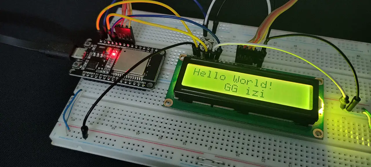
// Display The First Message In Home Position (0, 0) My_LCD.print("Hello World!"); // Set The Cursor Position To: [ Col 5, Row 1] // The Next Message Will Start From The 6th Char Position in The 2nd Row // Note: 1st Row Has An Index of 0, The 2nd Row Has An Index of 1 My_LCD.setCursor(5, 1); // Display The Second Message In Position (5, 1) My_LCD.print("GG izi"); |
We use the LCD_object.setCursor() function to set the cursor position, so the next LCD write operation occurs exactly at that location. And that’s it! Here is how it looks like in real-life testing.
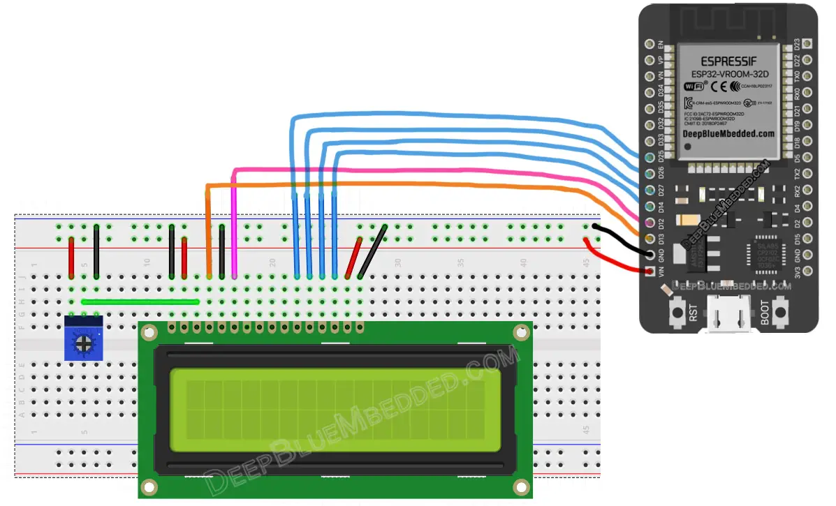
ESP32 LCD Connection Diagram
The diagram down below shows you the connection between ESP32 and the LCD 16×2 display (in 4-Bit data mode). Note that the LCD requires a +5v supply and the ESP32 is a 3.3v board, however, it’s got the USB Vbus available on the Vin pin. So, we’ll be using the Vin pin as a +5v source (it’s measured to be 4.7v but it’s sufficient indeed).
The 10k potentiometer here is used to control the Contrast of the display. Try adjusting the contrast level by turning this pot right and left for best visibility depending on the ambient light condition in the room you’re testing in.
| ESP32 | LCD Display |
| 13 | RS |
| 12 | EN |
| 14 | D4 |
| 27 | D5 |
| 26 | D6 |
| 25 | D7 |
Components For This Tutorial’s LABs
| QTY. | Component Name | Buy Links | |
| 1 | ESP32 Devkit v1 DOIT Board | Amazon.com – eBay.com – Banggood.com | |
| 2 | BreadBoard | Amazon.com – eBay.com – Banggood.com | |
| 1 | Resistors Kit | Amazon.com / Amazon.com – eBay.com – Banggood.com | |
| 1 | Jumper Wires Pack | Amazon.com / Amazon.com – eBay.com / eBay.com – Banggood.com | |
| 1 | LEDs Kit | Amazon.com / Amazon.com – eBay.com – Banggood.com | |
| 1 | Micro USB Cable | Amazon.com – eBay.com – Banggood.com | |
| 1 | LCD 16×2 Alphanumeric | Amazon.com – eBay – Banggood.com | |
*Affiliate Disclosure: When you click on links in this section and make a purchase, this can result in this site earning a commission. Affiliate programs and affiliations include, but are not limited to, the eBay Partner Network (EPN) and Amazon.com, Banggood.com. This may be one of the ways to support this free platform while getting your regular electronic parts orders as usual at no extra cost to you.
ESP32 LCD 16×2 Write Strings – LAB
| LAB Number | 14 |
| LAB Name | ESP32 LCD 16×2 Display Without I2C |
- Define an LCD object
- Initialize the LCD
- Write “Hello World!” at the home position and move the cursor to the middle of the second row, and write “GG izi”
ESP32 LCD Without I2C Writing Text – Code Example
The code example down below does the following: We start with including the LiquidCrystal library, then create an LCD object and initialize it. Then, we’ll write to the home position “Hello World!”, and move the cursor to the middle of the 2nd row and write “GG izi”. And nothing to be done in the main loop() function.
The Full code Listing
|
1 2 3 4 5 6 7 8 9 10 11 12 13 14 15 16 17 18 19 20 21 22 23 24 25 26 27 28 29 30 31 32 33 |
/* * LAB: 14 * Name: ESP32 LCD 16x2 Without I2C * Author: Khaled Magdy * For More Info Visit: www.DeepBlueMbedded.com */ #include <LiquidCrystal.h> // Create An LCD Object. Signals: [ RS, EN, D4, D5, D6, D7 ] LiquidCrystal My_LCD(13, 12, 14, 27, 26, 25); void setup() { // Initialize The LCD. Parameters: [ Columns, Rows ] My_LCD.begin(16, 2); // Clears The LCD Display My_LCD.clear(); // Display The First Message In Home Position (0, 0) My_LCD.print("Hello World!"); // Set The Cursor Position To: [ Col 5, Row 1] // The Next Message Will Start From The 6th Char Position in The 2nd Row // Note: 1st Row Has An Index of 0, The 2nd Row Has An Index of 1 My_LCD.setCursor(5, 1); // Display The Second Message In Position (5, 1) My_LCD.print("GG izi"); } void loop() { // Do Nothing... } |
Choose the board, COM port, hold down the BOOT button, click upload and keep your finger on the BOOT button pressed. When the Arduino IDE starts sending the code, you can release the button and wait for the flashing process to be completed. Now, the ESP32 is flashed with the new firmware.
Here is The Result
ESP32 LCD 16×2 Scrolling Text – LAB
| LAB Number | 15 |
| LAB Name | ESP32 LCD 16×2 Without I2C – Scrolling Text |
- Define an LCD object
- Initialize the LCD
- Write a 2-lines message
- Shift the entire display to the right 7 times, then to the left 7 times, and repeat!
ESP32 LCD Without I2C Scrolling Text – Code Example
|
1 2 3 4 5 6 7 8 9 10 11 12 13 14 15 16 17 18 19 20 21 22 23 24 25 26 27 28 29 30 31 32 33 34 35 36 37 38 39 40 41 42 43 44 |
/* * LAB: 15 * Name: ESP32 LCD 16x2 Without I2C - Scrolling Text * Author: Khaled Magdy * For More Info Visit: www.DeepBlueMbedded.com */ #include <LiquidCrystal.h> // Create An LCD Object. Signals: [ RS, EN, D4, D5, D6, D7 ] LiquidCrystal My_LCD(13, 12, 14, 27, 26, 25); void setup() { // Initialize The LCD. Parameters: [ Columns, Rows ] My_LCD.begin(16, 2); // Clears The LCD Display My_LCD.clear(); // Display The First Message In Home Position (0, 0) My_LCD.print("DeepBlue"); // Set The Cursor Position To: [ Col 0, Row 1] // The Next Message Will Start From The 1st Char Position in The 2nd Row // Note: 1st Row Has An Index of 0, The 2nd Row Has An Index of 1 My_LCD.setCursor(0, 1); // Display The Second Message In Position (0, 1) My_LCD.print("ESP32-LCD"); } void loop() { // Shift The Entire Display To Right 7 Times for(int i=0; i<7; i++) { My_LCD.scrollDisplayRight(); delay(500); } // Shift The Entire Display To Left 7 Times for(int i=0; i<7; i++) { My_LCD.scrollDisplayLeft(); delay(500); } } |
Demo Video For The Result
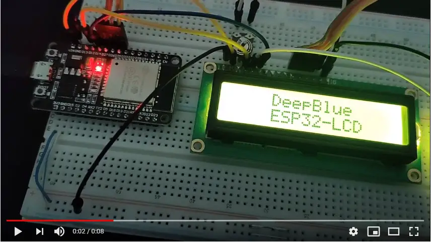
Click The image to watch the demo video on YouTube
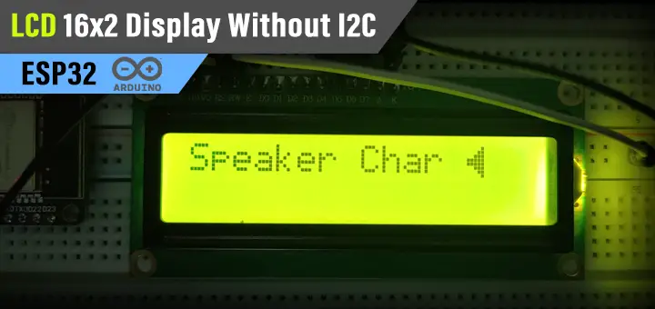
ESP32 LCD 16×2 Custom Characters – LAB
| LAB Number | 16 |
| LAB Name | ESP32 LCD 16×2 Without I2C – Custom Characters Generator |
- Define an LCD object
- Initialize the LCD
- Create your custom character using any tool (like this online tool)
- Write a string to the LCD and append to it the new character you’ve just created and added
Custom LCD Character Generator Online Tool
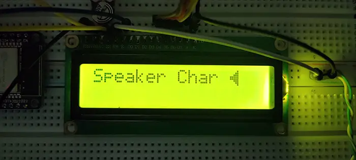
The LCD display’s controller (Hitachi HD44780) supports up to 8 custom characters that you can create and store on the LCD itself. Then you can send the Index of each custom character to be displayed later. Maybe 8 custom characters are not enough for your project, but it’s one little extra feature that you can occasionally use.
ESP32 LCD Without I2C Custom Character – Code Example
|
1 2 3 4 5 6 7 8 9 10 11 12 13 14 15 16 17 18 19 20 21 22 23 24 25 26 27 28 29 30 31 32 33 34 35 36 37 38 39 40 41 42 43 |
/* * LAB: 16 * Name: ESP32 LCD 16x2 Without I2C - Custom Character * Author: Khaled Magdy * For More Info Visit: www.DeepBlueMbedded.com */ #include <LiquidCrystal.h> // Create An LCD Object. Signals: [ RS, EN, D4, D5, D6, D7 ] LiquidCrystal My_LCD(13, 12, 14, 27, 26, 25); byte SpeakerChar[] = { B00001, B00011, B00111, B11111, B11111, B00111, B00011, B00001 }; void setup() { // Initialize The LCD. Parameters: [ Columns, Rows ] My_LCD.begin(16, 2); // Create a Custom Character (Speaker) My_LCD.createChar(0, SpeakerChar); // Clears The LCD Display My_LCD.clear(); // Display The First Message In Home Position (0, 0) My_LCD.print("Speaker Char "); // Append The New Char To The Message // Note That: byte(0) Now Represents Our 1st New Custom Char My_LCD.write(byte(0)); } void loop() { // Do Nothing... } |
Here is The Result
Extra Functions in Arduino LiquidCrystal Library
Those are some of the other functions available in the LiquidCrystal library that you may need to use in other projects. And check out the Arduino official reference for this library.
- home() – Return to the home position (0, 0)
- cursor() – Show the cursor
- noCursor() – Hide the cursor
- blink() – Make the cursor blink in its location
- noBlink() – Turn OFF cursor blink animation
- scrollDisplayLeft() – Shift the entire display to the left by one position (needs to be called repeatedly)
- scrollDisplayRight() – Shift the entire display to the right by one position (needs to be called repeatedly)
Learn More About LCD & How To Make Your Own LCD Library in Embedded-C
You can also check the ESP32 Course Home Page ???? for more ESP32 tutorials divided into sections based on categories. This may be helpful for you in case of searching for a specific tutorial or application.
Did you find this helpful? If yes, please consider supporting this work and sharing these tutorials!
Stay tuned for the upcoming tutorials and don’t forget to SHARE these tutorials. And consider SUPPORTING this work to keep publishing free content just like this!
| ESP32 Course Home Page ???? | |||||||
| Previous Tutorial | Tutorial 7 | Next Tutorial | |||||
Nice tutorial, thanks. I noticed the breadboard connections for the lcd1601 to ESP32 Devkit D4 – D7 are shown reversed, you have it consitant in the software lcd class init. and in the connection table but not in the breadboard diagram. It may lead to confusion for some!
Hi Khaled Magdy, Assalamualaikum. Nice tutorial ! thank you very much!