In this tutorial, you’ll learn how to use ESP32 interrupt pins in Arduino Core. We’ll also discuss how to use interrupts and write your interrupt service routine (ISR) for ESP32 external interrupt GPIO pins. Then, we’ll move to the Arduino Core libraries that implement drivers for the ESP32 interrupt pins and how to use its API functions, like attachInterrupt(). Without further ado, let’s get right into it!
| Previous Tutorial | Tutorial 6 | Next Tutorial | |||||
| ESP32 Interrupt Pins Tutorial (External GPIO Interrupt) – Arduino IDE | |||||||
| ESP32 Course Home Page ???? | |||||||
Table of Contents
- ESP32 Interrupt Pins Tutorial Requirements
- ESP32 External Interrupt Pins (IRQ)
- ESP32 External Interrupts Pins
- ESP32 Interrupt Example Code (in Arduino)
- ESP32 Interrupt Example (Toggle GPIO – LAB)
- ESP32 Interrupt Latency Measurement – LAB
- ESP32 Interrupt Pins Applications
ESP32 Interrupt Pins Tutorial Requirements
Prior Knowledge
- Nothing
Software Tools
Hardware Components
You can either get the complete course kit for this series of tutorials using the link down below. Or just refer to the table for the exact components to be used in practical LABs for only this specific tutorial.
ESP32 External Interrupt Pins (IRQ)
In most microcontrollers, there are some dedicated GPIO pins that have an interrupt event generation capability. Usually referred to as IRQ pins or external interrupt pins.
When the logic state of an external interrupt pin changes, it fires an interrupt signal to the CPU. So, the CPU suspends the main program execution and goes to handle a specific routine (or function) usually referred to as interrupt service routine (ISR).
An ISR should always be short with minimal logic operations and calculations because it’s going to happen a lot, so the main program execution will be suspended for longer periods of time. Which can potentially harm the timing behavior of your system.
ESP32 Interrupt Pins Usage Example
We can use external interrupt pins in various situations ranging from simple notification when a PIR sensor detects the motion of somebody in a room. And up to doing some measurement stuff and calculations like measuring the frequency of a digital sensor such as an “Optical Encoder” to measure a motor speed (RPM).
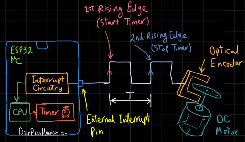
As you can see in the diagram shown above, the motor rotation causes the optical encoder to generate a square wave signal. By reading (measuring) the frequency of this signal, we can deduce the motor’s speed (RPM).
The digital signal is being measured in this application example by using an external interrupt pin + a Timer module. On the first rising edge, an interrupt occurs, so the CPU suspends the main program execution and starts a timer module, and then it resumes the main program.
On the next rising edge, an interrupt is fired, and the CPU suspends the main program and stops the timer. Now, the timer count can tell us the total time (T) or period of the signal. To get the frequency we’ll do (F = 1/T) and we’re done.
We’ll implement this exact system in a future tutorial, so keep checking this series of tutorials every now and then.
ESP32 External Interrupts Pins
ESP32 Interrupts
There are so many different sources for interrupts in the ESP32 interrupt matrix. The Interrupt Matrix embedded in the ESP32 independently allocates peripheral interrupt sources to the two CPUs’ peripheral interrupts.
It does accept 71 peripheral interrupt sources as input. And it generates 26 peripheral interrupt sources per CPU as output (52 in total).
Interrupts in ESP32 are categorized as hardware interrupts and software interrupts.
- Hardware Interrupts – These are interrupts that are being fired by hardware peripherals or sources. They can be: Internal or External. An example of an internal hardware interrupts may be something like a hardware timer interrupt or WDT. An example of an external hardware interrupt is external GPIO pins interrupts (the topic of this tutorial).
- Software Interrupts – These are interrupts that are being fired by the user, the programmers. Manually inserted in certain pieces of the code to indicate something or to do an IO request or something.
ESP32 GPIO Interrupt Pins
All ESP32 GPIO pins are interrupt-capable pins. You can enable the interrupt functionality to any GPIO input pin using this function from the Arduino Core.
attachInterrupt(GPIO_pin, ISR, Event);
We’ll get into the details of this function and how to use it in the next section.
Refer to this ESP32 devkit board pinout.
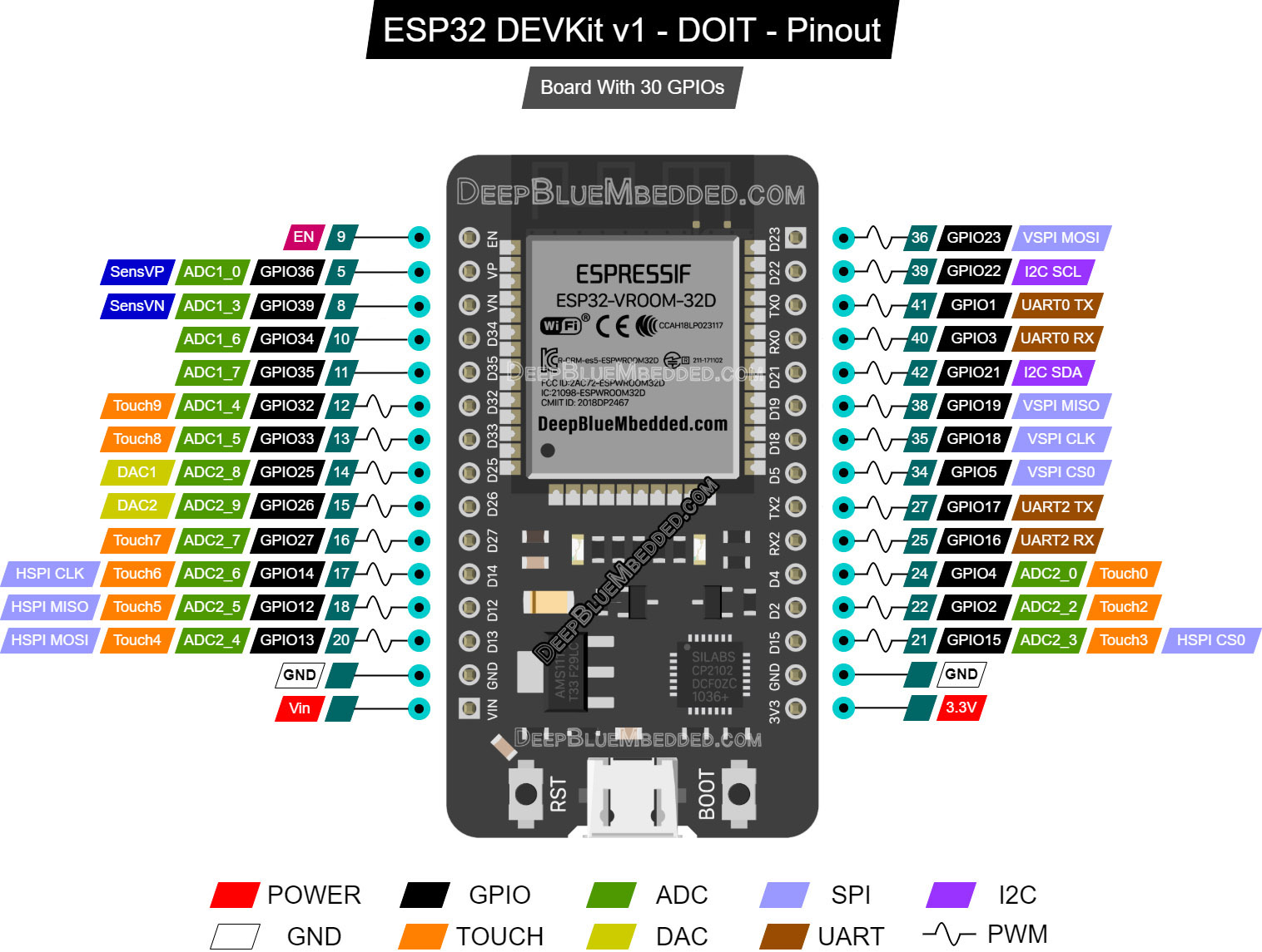
(if it’s not clear, right-click and open it in a new tab for a larger view)
ESP32 Interrupt Trigger Edge (Events)
There are 5 different events to trigger an interrupt for each external interrupt pin. You can programmatically choose the event at which an interrupt is fired as per the application. Those events are as follows:
| RISING | An interrupt is fired on each Rising Edge |
| FALLING | An interrupt is fired on each Falling Edge |
| HIGH | An interrupt is fired whenever the pin is HIGH |
| LOW | An interrupt is fired whenever the pin is LOW |
| CHANGE | An interrupt is fired whenever the pin’s state changes, from High to LOW or From LOW to HIGH |
ESP32 Detach Interrupt (External Interrupt Disable)
You can of course disable the external interrupt functionality for any interrupt pin whenever you want in your code. By using this function from Arduino Core, you can disable any external interrupt pin.
detachInterrupt(GPIO_pin);
ESP32 ISR (Interrupt Service Routine) Handler
As we’ve stated earlier, the ISR (interrupt service routine) is the special function that the CPU starts executing in response to an interrupt event. the CPU does suspend the main program in order to handle the ISR, so it has to be a lightweight piece of code.
To define the ISR function, you should use the following format:
void IRAM_ATTR Ext_INT1_ISR()
{
    // Your Code...
}
The IRAM_ATTR identifier is recommended by Espressif in order to place this piece of code in the internal RAM memory instead of the flash. It’s going to be executed much faster in this way and results in a very quick context switching and servicing for the interrupt. We’ll measure this by the end of this tutorial as well.
ESP32 Interrupt Example Code (in Arduino)
In this section, I’ll give you a step-by-step approach for what to do in order to configure and initialize an external interrupt pin and assign it to an ISR handler function.
Step1– Decide on the external interrupt GPIO input pin that you’re going to use.
Step2– Decide on the Interrupt Trigger Event that you need to have. (RISING – FALLING – HIGH – LOW – CHANGE)
Step3– Initialize that GPIO input pin & AttachInterrupt to it in the setup function
void setup()
{
  pinMode(GPIO_pin, INPUT);
  attachInterrupt(GPIO_pin, Ext_INT1_ISR, RISING);
}
Step4– Now, write your own ISR function. What do you want to do when this input pin has a rising edge input?
void IRAM_ATTR Ext_INT1_ISR()
{
  // Do Something ...
}
And that’s it!
Let’s do some practical LAB examples to test this out.
ESP32 Interrupt Example (Toggle GPIO – LAB)
| LAB Number | 12 |
| LAB Name | ESP32 External Interrupt GPIO Pins |
- Define an output pin (for the LED)
- Define an input pin & Attach interrupt to it
- Write the ISR function to toggle the LED pin on each RISING edge
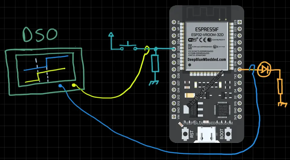
Connection Diagram
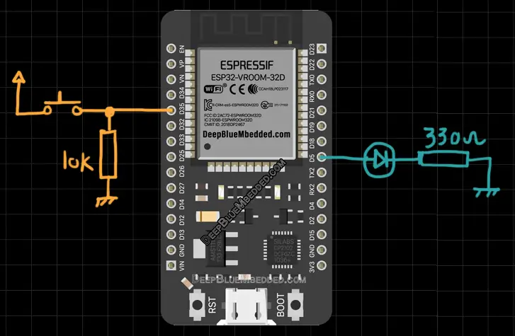
ESP32 External Interrupt Pins – Code Example
The code example down below does the following: We start with defining the LED GPIO pin (GPIO5), the input pin for the external interrupt (GPIO35), and attachInterrupt() to it. Then, we’ll toggle the LED pin in the ISR handler routine.
The Full code Listing
/*
 * LAB: 12
 * Name: ESP32 External Interrupts
 * Author: Khaled Magdy
 * For More Info Visit: www.DeepBlueMbedded.com
*/

#define Btn1_GPIO   35
#define LED1_GPIO   5

void IRAM_ATTR Ext_INT1_ISR()
{
  // Toggle The LED
  digitalWrite(LED1_GPIO, !digitalRead(LED1_GPIO));
}

void setup()
{
  pinMode(LED1_GPIO, OUTPUT);
  pinMode(Btn1_GPIO, INPUT);
  attachInterrupt(Btn1_GPIO, Ext_INT1_ISR, RISING);
}

void loop()
{
  // Do Nothing...
}
Choose the board, COM port, hold down the BOOT button, click upload and keep your finger on the BOOT button pressed. When the Arduino IDE starts sending the code, you can release the button and wait for the flashing process to be completed. Now, the ESP32 is flashed with the new firmware.
Demo Video For The Result
Note that the LED pin will toggle sometimes randomly due to the button bouncing issue. This can be resolved by adding a small RC filter or a Schmitt-trigger debouncing circuit. Any hardware solution will work just as fine.
And remember that no software debouncing can prevent hardware interrupts from firing. You can debounce a GPIO input button in software but not external hardware interrupts, unfortunately. This requires only hardware debouncing techniques.
ESP32 Interrupt Latency Measurement – LAB
| LAB Number | 13 |
| LAB Name | ESP32 Interrupt Latency Measurement |
Interrupt Latency – is the time it takes the CPU to respond to a specific interrupt signal. It’s a measure for the response time of an interrupt and it’s desired to be as small as possible. Upon an interrupt signal reception, the CPU suspends the current main code executions, saves the context, switches the context to the ISR, executes the ISR code, switches the context back to main, and finally resumes the main code execution.
This takes some time and it’s desired to be as small as possible. The time between the hardware interrupt signal and the start of ISR execution (interrupt latency) is what we’re going to measure in this LAB.
ESP32 Interrupt Latency Measurement – Code Example
The same as the previous LAB.
Screenshot For The Result
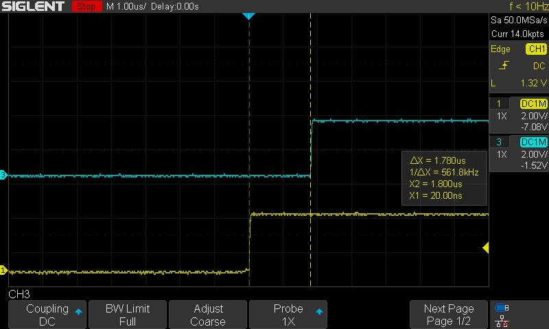
It’s roughly 1.8 µs. This is pretty quick indeed, it took the CPU only 1.8 µs to respond to the external input button interrupt and change the LED GPIO pin state. Note that this test was done with the CPU running @ 240MHz. Running at a lower CPU frequency will definitely increase the time it takes to respond to an interrupt signal.

This article will give more in-depth information about Interrupt Latency and response. And how to measure it practically and what are the possible ways to reduce this time for a faster interrupt response.
Required Parts For Example LABs
| QTY. | Component | Buy |
| 1 | ESP32 Devkit v1 DOIT Board | Amazon.com – eBay.com – Banggood.com |
| 2 | BreadBoard | Amazon.com – eBay.com – Banggood.com |
| 1 | Resistors Kit | Amazon.com / Amazon.com – eBay.com – Banggood.com |
| 1 | Jumper Wires Pack | Amazon.com / Amazon.com – eBay.com / eBay.com – Banggood.com |
| 1 | LEDs Kit | Amazon.com / Amazon.com – eBay.com – Banggood.com |
| 1 | Potentiometers | Amazon.com / Amazon.com – eBay – Banggood.com |
| 1 | Micro USB Cable | Amazon.com – eBay.com – Banggood.com |
★ Check The Full Course Complete Kit List & LAB Test Equipment Required For Debugging
Download Attachments
You can download all attachment files for this Article/Tutorial (project files, schematics, code, etc..) using the link below. Please consider supporting my work through the various support options listed in the link below. Every small donation helps to keep this website up and running and ultimately supports our community.
ESP32 Interrupt Pins Applications
ESP32 External interrupt pins can be used in so many applications as we’ll see in the future tutorials. I’ll keep updating this series of tutorials by adding more applications and techniques that may help you in your projects. Drop me a comment if you’ve got any questions or suggestions, I’ll be glad to help!
Related Tutorials Based On ESP32 External Interrupts Pins
- ESP32 + Optical Encoder Motor RPM Measurement
- ESP32 & PIR Sensor Motion Detection
- ESP32 & HC-SR04 Ultrasonic Sensor Interfacing
- And More…
You can also check the ESP32 Course Home Page ???? for more ESP32 tutorials divided into sections based on categories. This may be helpful for you in case of searching for a specific tutorial or application.
Excellent material and explanation, I’m following every tutorial and learning a lot of new concepts, congratulations for this course and for your time to write it. I hope that you can also continue with the STM32 too ???? ????, I’m in several groups of telegram (spanish language) and perhaps would be a good way to promote your excellent material, I’ll recomend this site of course ????
I have one question: what you mean when you write “You can debounce a GPIO input button in software but not external hardware interrupts …”, this is not clear for me, I know that I can debounce a switch in several ways by software …
many thanks for your time in advance
Cheers from Argentina
Hi Horacio!
Thanks so much for your kind words .. This means a lot to me!
I’ll do my best to push maybe 30 or 40 ESP32 tutorials. And then keep guggling between ESP32 & STM32 for the upcoming months.
What I mean by the statement you’ve asked for is the following:
– You can debounce a GPIO pin in software or in hardware it’s up to you actually because the CPU reads the pin state and then react correspondingly depending on what you’re doing in your application.
– However, when you’ve already set a specific pin to fire an interrupt. It’s like hard-wired to the CPU interrupt signal. Now, there is no way to debouce a button once an interrupt is fired! I’m speaking about what you can do in software. The button can maybe fire 10 interrupts until it settles. That’s why it’s better to debounce it in hardware rather than in code. I believe you can still implement some debouncing logic inside the ISR, but I’d not recommend this in many situations.
Image this system: a push-button is used to increment a counter variable. It’s hooked to an interrupt pin and it’s not debounced. Pushing the button only one time maybe will fire 5 interrupts! Now, in the ISR, should you increment the counter variable in each interrupt? That’s the issue I’m talking about.
Hi Khaled,
Many thanks for your fast response, I’ll be very happy learning your new tutorials and labs !!!
I asked you for that statement because I have worked since 1980 to now, with microprocessors (motorola 8 bits, now NXP) and I had never used hardware debounce solutions, I have sold thousands of control access controllers with many irq inputs, that worked without any fail …, but the hard debounce solution is very cheap today so it’s a good idea to make both simultaneously.
My approach to debounce a pin is: first attach that pin to an Irq, in the ISR set a flag when interrupt trigger this function (very short time attending the event), also for my sistem I have a general timer interrupt every 5 to 10 ms, in this timer interrupt I analyse this flag every 5 ms, if the flag is set I read the pin value, if high I increment an 8 bit counter, if low I decrement the same counter, then check for a threshold value up or down of this counter to determine the filtered level of my pin, then reset the flag to enable a new button press, this method adapts to different noisy switches (not a fixed amount of time like the common solution), I know that it’s not a perfect solution but works fine for me, also in 4×4 matrix keyboards, and of course since this days I have programmed everything in Assembler ????
Sorry about my bad english, I don’t know if you understand my “not so good writing”, but it’s a pending task to improve … it’s in my to do list too
Kind regards and continue with your excellent work
Horacio
I saw in a chat thread that interrupts can even be used to increase ADC sampling rate. I couldn’t understand how. could you kindly let me know if you can ?
I think they’re talking about adm in dma mode which can be done under espressif idf framework. IDK if it’s achievable in Arduino Core or not. But as far as I’ve seen in the documentation and APIs, it’s not implemented.