| Previous Tutorial | Tutorial 8 | Next Tutorial | |||||
| ESP32 I2C Tutorial: Set Pins, Multi Devices, I2C Scanner (Arduino IDE) | |||||||
| ESP32 Course Home Page ???? | |||||||
In this tutorial, you’ll learn about ESP32 I2C communication protocol (in Arduino IDE). We’ll discuss how ESP32 I2C works, how to change I2C default pins (SDA, SCL), how to connect multiple I2C devices on the bus with proper addressing, and how to create an ESP32 I2C scanner to check for available I2C devices on the bus and get their addresses.
Then, we’ll move to the Arduino Core libraries that implement drivers for the ESP32 I2C peripheral and how to use its API functions. It’s something similar to the commonly known Arduino Wire library as we’ll see. Without further ado, let’s get right into it!
[toc]
Requirements For This Tutorial
Prior Knowledge
- Nothing
Software Tools
Hardware Components
You can either get the complete course kit for this series of tutorials using the link down below. Or just refer to the table for the exact components to be used in practical LABs for only this specific tutorial.
I2C Serial Communication Protocol
I2C (i-square-c) is an acronym for “Inter-Integrated-Circuit” which was originally created by Philips Semiconductors (now NXP) back in 1982. The I2C is a multi-master, multi-slave, synchronous, bidirectional, half-duplex serial communication bus.
It’s widely used for attaching lower-speed peripheral ICs to processors and microcontrollers in short-distance, intra-board communication. Just as external EEPROMs, Digital Temperature Sensors, LCD Controllers, OLED Display, RTC, and much more.
I2C Modes & Communication Speeds
Originally, the I2C-bus was limited to 100 kbit/s operations. Over time there have been several additions to the specification so that there are now five operating speed categories. Standard-mode, Fast-mode (Fm), Fast-mode Plus (Fm+), and High-speed mode (Hs-mode)
Bidirectional bus:
- Standard-Mode (Sm), with a bit rate up to 100 kbit/s
- Fast-Mode (Fm), with a bit rate up to 400 kbit/s
- Fast-Mode Plus (Fm+), with a bit rate up to 1 Mbit/s
- High-speed Mode (Hs-mode), with a bit rate up to 3.4 Mbit/s.
Unidirectional bus:
- Ultra Fast-Mode (UFm), with a bit rate of up to 5 Mbit/s
Note: You have to refer to the specific device datasheet to check the typical details for the i2c hardware specifications that have actually been implemented on-chip.
I2C Bus Lines
The I2C is a 2-wire communication interface, so it’s got only 2 lines on the bus. SDA for data, and SCL for clock and both of them are bidirectional (send or receive).
To connect any I2C device to your microcontroller, you’ll only need to hook it to the 2-wire bus and it’s ready to send/receive data. It’s very easy to connect/disconnect I2C devices compared to many other communication interfaces.
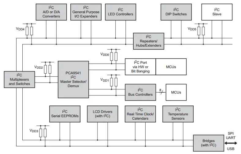
Note: Both lines (SDA & SCL) should be “Pulled-Up” by external resistors as you can see in the diagram above. Sometimes you’ll find the pull-up resistors on each I2C device board. You need only 2 resistors for (SDA & SCL) per I2C.
As you might have noticed in the diagram above, there are I2C bus multiplexors to extend the addresses. Those are considered “independent” I2C buses, hence we need to Pull-Up the (SDA & SCL) for each extra independent I2C bus.
I2C Device Addressing
The I2C standards support 2 addressing modes. By default, it’s a 7-Bit addressing mode which means you can communicate with up to 127 different devices on the bus (0x00 address is reserved by I2C standards).
There is also a 10-Bit addressing mode that extends the number of devices that can be addressed on the bus significantly. We’re limited by the total bus capacitance in practice and it’s better to use I2C bus bridges/multiplexors in some cases.
I2C Full Guide (Tutorial)
This is a full I2C Tutorial (Guide) using the I2C standards document that explains how serial communication works, different elements of I2C communication, open-drain output drivers, bus arbitration, clock stretching, clock synchronization, and much more.
If you’re really interested in learning how it works on a very low level and creating your own I2C communication driver in Embedded-C language, it’d definitely be a great resource for you. Be informed that it’s like a +10k words article! But hopefully, it’s going to be very helpful.
| Check this in-depth tutorial for more information about I2C serial communication | |
 |
 |
ESP32 I2C Peripheral
In this section, we’ll have a look at the ESP32 I2C hardware capabilities, how it works, and what kind of features it has. So you can use it in an efficient way depending on the specific application requirements you have.
ESP32 I2C Hardware Features
The ESP32 SoC has Two I2C interface controllers (I2C0, I2C1). They are identical in operation and everything else, and here are some of the main features for each I2C controller in ESP32.
- Supports both master mode and slave mode
- Supports multi-master and multi-slave communication
- Supports standard mode (100 kbit/s)
- Supports fast mode (400 kbit/s)
- Supports 7-bit addressing and 10-bit addressing
- Supports continuous data transmission with disabled Serial Clock Line (SCL)
- Supports programmable digital noise filter
ESP32 I2C Default Pins
As we’ve stated earlier in this series of tutorials, all ESP32 peripherals are interconnected together internally via a GPIO Matrix and you’ve got also a GPIO Mux. This enables you, the user (programmer), to route any peripheral signal to any GPIO pin. But, by default, each peripheral’s signal is routed to a default pin. Those are the I2C pins for (I2C0, I2C1):
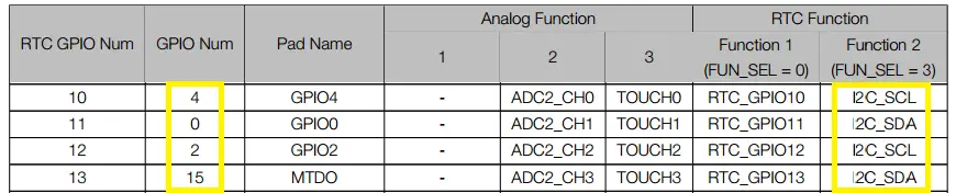
This is as stated in the datasheet of the ESP32. The problem is some of those GPIO pins are not accessible in many ESP32 modules. Therefore, the Arduino Core driver for I2C had to make use of the GPIO matrix & Mux to re-route those signals to other “more accessible” pins. The following pins are the default I2C0 pins in Arduino Core:
| SCL | GPIO22 |
| SDA | GPIO21 |
This is when you use the generic Arduino Wire library as shown below
| Wire.begin(); |
But, what I do recommend is to use the TwoWire object that enables you to define an I2C bus with the (SCL & SDA) signals being routed to custom GPIO pins that you choose on your own. This is a much better way in my opinion and gives you all the freedom in your design. This is shown in the next section down below.
ESP32 Set I2C Pins (SDA, SCL)
When you include the Arduino Core I2C driver “Wire.h“, it’s by default set to I2C0 peripheral, and the (SDA & SCL) lines are set to defaults as shown in the previous section. However, you can still change the ESP32 I2C default pins in the setup function and route those signals to any GPIO pins you want. As shown below
| Wire.begin(SDA0_Pin, SCL0_Pin); |
But what I do really recommend is using the TwoWire object to create an instance of the I2C bus and assign the GPIO pins you want for the SDA & SCL signals for each peripheral. As shown next
|
1 2 3 4 5 6 7 8 9 10 11 12 13 14 15 16 17 18 |
#include <Wire.h> #define I2C_Freq 100000 #define SDA_0 21 #define SCL_0 22 #define SDA_1 18 #define SCL_1 19 TwoWire I2C_0 = TwoWire(0); TwoWire I2C_1 = TwoWire(1); void setup() { I2C_0.begin(SDA_0 , SCL_0 , I2C_Freq ); I2C_1.begin(SDA_1 , SCL_1 , I2C_Freq ); } |
This way gives you all the freedom you need in your design to assign any GPIO pin to any I2C peripheral of the 2 we’ve got in the ESP32. And we’ll be testing this in the LABs hereafter in this tutorial.
ESP32 I2C Communication (Arduino IDE)
You can use the ESP32 I2C interface to communicate with a wide variety of sensors and modules (such as MPU6050 IMU, OLED Display, RTC, I2C LCD, etc). In this section, I’ll give you a step-by-step approach to using ESP32 I2C in Arduino IDE for your project code.
Step1– Include the Arduino Core I2C wire library
| #include <Wire.h> |
Step2– Define the I2C_Frequency and GPIO pins to be used for (SDA & SCL) lines
|
1 2 3 4 |
#define I2C_Freq 100000 #define SDA_0 18 #define SCL_0 19 |
Step3– Create a TwoWire I2C Object and assign hardware peripheral to it (I2C0 or I2C1)
| TwoWire I2C_0 = TwoWire(0); |
Step4– In the void setup() function, initialize that I2C interface as shown below
|
1 2 3 4 |
void setup() { I2C_0.begin(SDA_0 , SCL_0 , I2C_Freq); } |
Now, you’re good to go. You can assign this TwoWire I2C object (I2C_0) to any sensor’s object and follow its library’s examples. And use it however you want in your project.
Next, we’ll be creating a couple of projects to put everything we’ve discussed under test and introduce more topics related to I2C addresses and I2C device configurations on the bus.
Components For This Tutorial’s LABs
| QTY. | Component Name | Buy Links |
| 1 | ESP32 Devkit v1 DOIT Board | Amazon.com – eBay.com – Banggood.com |
| 2 | BreadBoard | Amazon.com – eBay.com – Banggood.com |
| 1 | Resistors Kit | Amazon.com / Amazon.com – eBay.com – Banggood.com |
| 1 | Jumper Wires Pack | Amazon.com / Amazon.com – eBay.com / eBay.com – Banggood.com |
| 1 | LEDs Kit | Amazon.com / Amazon.com – eBay.com – Banggood.com |
| 1 | Micro USB Cable | Amazon.com – eBay.com – Banggood.com |
| 2 | I2C LCD Module | Amazon.com Amazon.com – eBay – Banggood.com |
*Affiliate Disclosure: When you click on links in this section and make a purchase, this can result in this site earning a commission. Affiliate programs and affiliations include, but are not limited to, the eBay Partner Network (EPN) and Amazon.com, Banggood.com. This may be one of the ways to support this free platform while getting your regular electronic parts orders as usual at no extra cost to you.
ESP32 I2C Scanner (Arduino IDE) – LAB
The I2C Scanner example is a very common Arduino sketch example to scan the I2C bus for available devices and get their addresses (if found). That can be useful if you don’t know the address of any I2C device or just not sure about it. Just run this example and get its addresses.
It can also tell if an I2C device is actually working or not. Maybe the device you’re trying to communicate with is actually damaged and no longer works. Then, it can be handy to run this example and make sure everything is OK.
| LAB Number | 17 |
| LAB Name | ESP32 I2C Scanner Example |
ESP32 I2C Scanner – Arduino Code Example
The code example down below does the following: We start with defining initializing the I2C peripheral. And we’ll also initialize a serial UART communication to print back the results to the PC serial terminal (Arduino Monitor).
Then, we’ll start to check all possible I2C address devices (7-Bit = 127 possible addresses excluding 0x00). If there is an ACK, it means there is a working I2C device at that address so we shall print it out. If no ACK (NACK) is received, we shall move to the next address until the end.
The Full code Listing (Modified Version of This Source)
|
1 2 3 4 5 6 7 8 9 10 11 12 13 14 15 16 17 18 19 20 21 22 23 24 25 26 27 28 29 30 31 32 33 34 35 36 37 38 39 40 41 42 43 44 45 46 47 48 49 50 51 52 53 54 55 56 57 58 59 60 61 62 |
/* * LAB: 17 * Name: ESP32 I2C Scanner * Author: Khaled Magdy * For More Info Visit: www.DeepBlueMbedded.com */ #include <Wire.h> #define I2C_Freq 100000 #define SDA_0 18 #define SCL_0 19 TwoWire I2C_0 = TwoWire(0); void setup() { Serial.begin(115200); I2C_0.begin(SDA_0 , SCL_0 , I2C_Freq); } void loop() { byte error, address; int nDevices; Serial.println("Scanning..."); nDevices = 0; for(address = 1; address < 127; address++ ) { // The i2c_scanner uses the return value of // the Write.endTransmisstion to see if // a device did acknowledge to the address. I2C_0.beginTransmission(address); error = I2C_0.endTransmission(); if (error == 0) { Serial.print("I2C device found at address 0x"); if (address<16) Serial.print("0"); Serial.print(address,HEX); Serial.println(" !"); nDevices++; } else if (error==4) { Serial.print("Unknown error at address 0x"); if (address<16) Serial.print("0"); Serial.println(address,HEX); } } if (nDevices == 0) Serial.println("No I2C devices found\n"); else Serial.println("done\n"); delay(5000); // wait 5 seconds for next scan } |
Choose the board, COM port, hold down the BOOT button, click upload and keep your finger on the BOOT button pressed. When the Arduino IDE starts sending the code, you can release the button and wait for the flashing process to be completed. Now, the ESP32 is flashed with the new firmware.
Those are the GPIO pins I’ve used for I2C_0 in this example code:
| SCL | GPIO19 |
| SDA | GPIO18 |
Test #1 Setup & Results
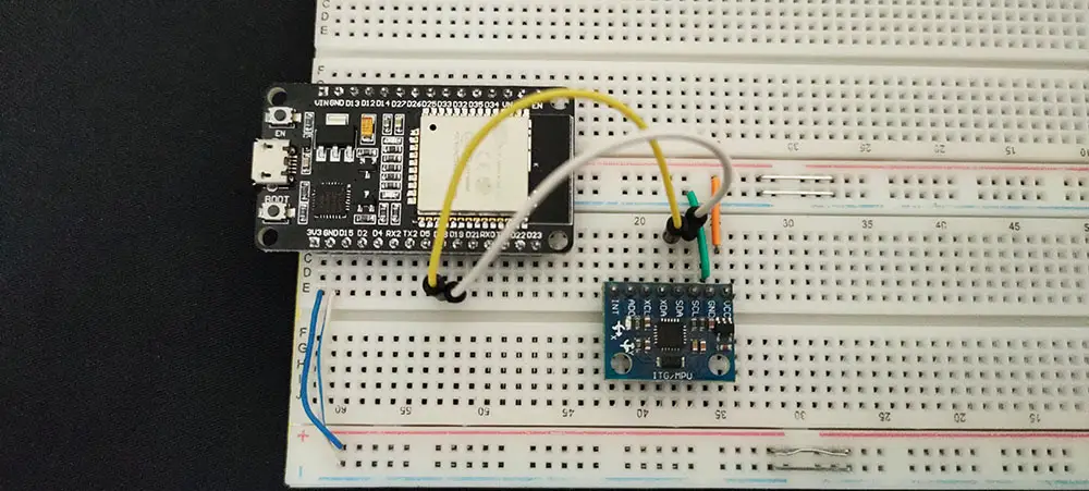
For the first test, I’ve connected an MPU6050 IMU sensor to the SCL & SDA lines of I2C1 as you can see in the image down below. The I2C address for this slave device is 0x68 as stated in the datasheet.
e can change only one bit of that address so there could be 2 MPU6050 sensors on the same bus at maximum. Anyway, we should expect to see that address after running the example on the “Tera Term” serial terminal on my PC.
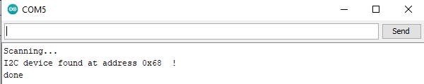
And Here Is The Result
Test #2 Setup & Results
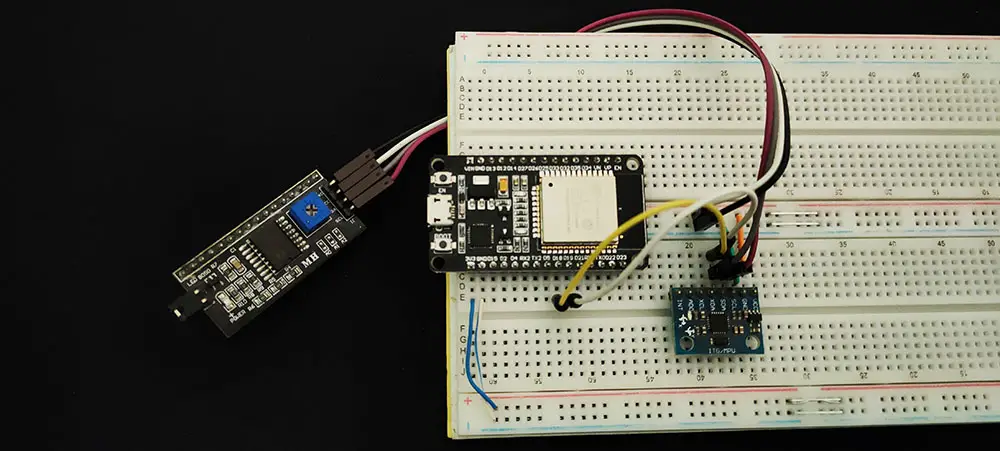
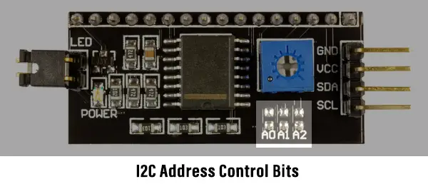
In the second test, I’ve just added another I2C module to the bus lines which is the I2C_LCD interface IO expander (PCF8574T). This module has an I2C slave address of 0x27 as a default address if no solder bridge on the module’s board is touched at all.
You can still play around with those bridges to change the device address to allow many I2C_LCD devices on the same bus. Which we’ll be doing in the next tutorial and will be discussed hereafter in this tutorial.
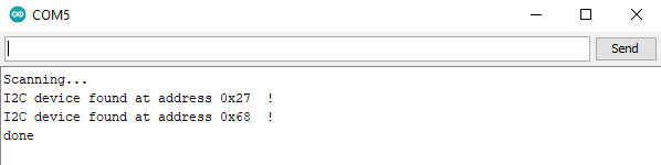
And Here Is The Result
ESP32 I2C Device Addresses Limitations
No multiple devices are allowed to have the exact same I2C address on the bus. Usually, manufacturers give you, the designer, a couple of IO pins to set the address of that I2C device (like an LCD, EEPROM, RTC). So that you can have multiple units of the same device on the same I2C bus.
To further investigate this matter and provide some solution, let’s first define a problem statement and start searching for a convenient solution. Here is an I2C LCD (IO expander) called PCF8574. Its default address in the datasheet is 0x27 with all solder bridges open.
What if we’d like to hook up 3 units of I2C LCD on the exact same bus and control those LCDs with our ESP32. What can we do to make this happen?
Here are the proposed solution one by one (ordered by my personal recommendations)
1- Change The I2C Device Address
The first thing you should consider is to take advantage of the 3 bits of address available to you in the form of solder bridges. By mixing 0’s and 1’s, you’ll end up having 8 different unique addresses for 8 x I2C LCD units all working on the exact same bus.
We want just 3, so it’s more than enough. Let’s now change the problem statement, and let’s say we need to have 10 x I2C LCD units on the exact same bus. What to do?
2- ESP32 + I2C Expander
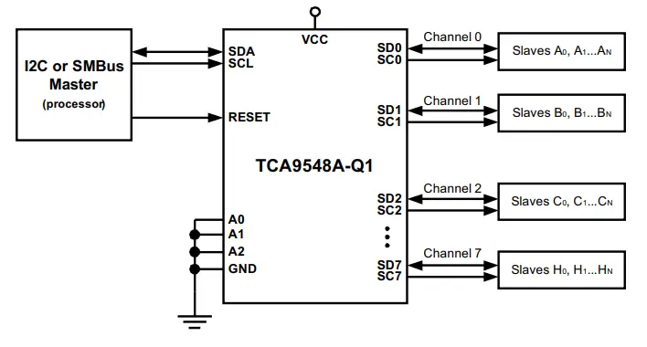
Next, we can consider getting an I2C expander IC like (TCA9548A). It’s a very cheap solution to give some virtual addresses to identical I2C devices so that you become able of addressing each device on the bus with a unique address.
Here is a simplified diagram for this I2C expander chip. Note that it has its own I2C address and you can have multiple units of this expander IC so it does increase the addressable device significantly at a very low cost.
3- Use All ESP32 Hardware I2C Interfaces
What if we don’t want to add an extra chip to the BOM? Well, there is no way around this actually. But fortunately, the ESP32 has another I2C peripheral that can be used to double the number of devices that you can address.
As I’ve said earlier, by changing the solder bridges we can address up to 8 x I2C LCDs, now we’ve got 2 x I2C peripherals. So, we can easily solve the required 10 x I2C LCD problem.
4- ESP32 Software I2C (Bit-Banging)
One last solution that I don’t usually recommend is by using “Bit-Banging”. Actually, most serial communication protocols can be Bit-Banged by a microcontroller. It’s a software-emulated version that uses normal GPIO pins to simulate the I2C signaling on the bus.
It acts as if it’s a hardware I2C that’s generating the signals, but in reality, it’s the CPU doing all of this with certain timing constraints and vulnerable to all sorts of errors and issues. But it’s still doable and being used under certain circumstances.
ESP32 I2C Applications
ESP32 I2C interfaces can be used in so many applications as we’ll see in future tutorials. I’ll keep updating this series of tutorials by adding more applications and techniques that may help you in your projects. Drop me a comment if you’ve got any questions or suggestions, I’ll be glad to help!
Related Tutorials Based On ESP32 I2C
- ESP32 I2C LCD
- ESP32 MPU6050 IMU
- ESP32 I2C RTC Interfacing
- And More…
Learn More About I2C in General
- Full I2C Serial Communication Guide Tutorial
- Build Your Own I2C MPU6050 Library (in Embedded-C)
- Build Your Own I2C LCD Library (in Embedded-C)
You can also check the ESP32 Course Home Page ???? for more ESP32 tutorials divided into sections based on categories. This may be helpful for you in case of searching for a specific tutorial or application.
Did you find this helpful? If yes, please consider supporting this work and sharing these tutorials!
Stay tuned for the upcoming tutorials and don’t forget to SHARE these tutorials. And consider SUPPORTING this work to keep publishing free content just like this!
| ESP32 Course Home Page ???? | |||||||
| Previous Tutorial | Tutorial 8 | Next Tutorial | |||||