| Previous Tutorial | Tutorial 0 | Next Tutorial | |||||
| Getting Started With ESP32 – Arduino | |||||||
| ESP32 Course Home Page ???? | |||||||
This article is the starting point if want to learn ESP32 programming with Arduino. We’ll also explore all other frameworks to develop ESP32 projects like (Espressif IDF – MicroPython – AT Commands). It’s going to be a complete getting started guide for the ESP32 development boards and the embedded IoT applications development environment. The ESP32 is the successor to ESP8266 from Espressif with a more powerful Dual-Core processor & Wi-Fi / BLE capability.
Here, you’ll be introduced to the ESP32 boards and features, the available development IDE options for ESP32, and get started with the ESP32 Arduino Core as a development framework. There are plenty of other options as we’ll see, and I’ll be making some other short series of tutorials for each framework. With that being said, let’s get started with ESP32 Arduino Tutorials Series!
[toc]
ESP32 Features & Specs
The ESP8266 was a very powerful Wi-Fi accessory for Arduino projects and other microcontroller-based IoT applications for quite a long time. It was actually several times more powerful than Arduino boards and most of the 8-bit microcontrollers out there. Until the release of its successor, the ESP32 chips. Here is a quick comparison between the typical Arduino boards, ESP8266, ESP32, and raspberry pi zero.
| Arduino | ESP8266 | ESP32 | Raspberry pi 0 W | |
| Microprocessor | AVR Atmega328P | Tensilica Xtensa LX106 | Tensilica Xtensa LX6 | ARM |
| Arch. | 8-Bit | 32-Bit | 32-Bit | 32-Bit |
| # Cores | 1 Core | 1 Core | 2 Cores + ULP | 1 Core + 1 GPU |
| F_cpu | 20MHz | 80-160MHz | 240MHz | 1GHz |
| RAM | 2KB | 160KB | 520KB | 512MB |
| FLASH | 32KB | 4MB | 16MB | External MicroSD |
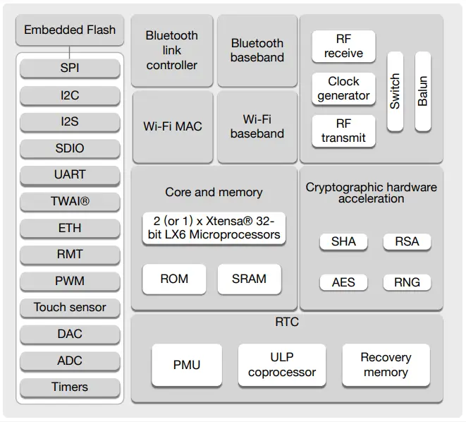
As you can see from the table above, the ESP32 is a much more powerful upgrade over the ESP8266 and a little bit more optimized than raspberry pi 0 W. For a very low price, you get a Dual-Core processor with an additional Ultra-Low Power CPU for Low-Power applications, and Wi-Fi / BLE (smart Bluetooth) on-chip with so many hardware features as you can see in the diagram below.
ESP32 Internal Functional Block Diagram
| CPU Features & Memories
Clocks & Timers Features
|
Hardware Peripherals
|
|
You should also know that the ESP32 chip itself is a 48 pin package most of which are not usable GPIO pins. The GPIO pins that you can use are up to 34 pins. Also, note that different ESP32 development boards will give you access to some of those pins or most of them in some cases. But it’s different from one board to another as we’ll see in the next section down below. |
ESP32 Development Boards
In this section, I’ll show you the most popular ESP development boards with a brief history of how they’ve been developing over the past few years and what are the possible options that you can use to follow along with this course (series of tutorials). So here we go!
|
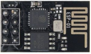
ESP8266 This is how it got started! This small ESP-01 module has been a very popular accessory for adding Wi-Fi connectivity for IoT applications. It’s been used with Arduino & other Microcontrollers as a slave device (module) which we control over UART using AT Commands. Until the moment when somebody realized that it’s a way more powerful chip than most of the target microcontrollers that we were using to control it! With far more memory, CPU computational power, built-in Wi-Fi, and so on. Therefore, it paved the way to have its own dev board that got supported by Arduino later on. Which is the next board down below. |
 |
|
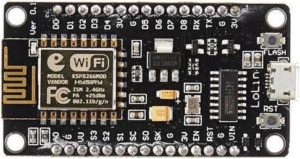
ESP8266 NodeMCU This board did become a very popular development board for ESP8266 that can be programmed in so many different ways. The most popular one among all was the Arduino IDE. It’s really a great option until the release of its successor, the ESP32. Which has several more features that ESP8266 lacks like Bluetooth support, a more powerful CPU, a rich variety of peripherals like ADC, DAC, I2C, ATWI, etc. |
 |
|
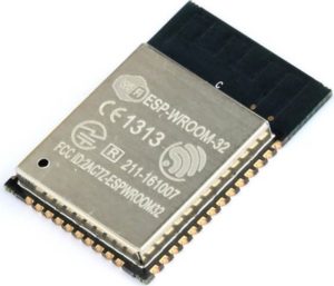
ESP32 (WROOM-32 Module) Now, we’ve everything we need in one module. It’s got the ESP32 chip with an onboard Antenna + proper shielding which is certified and considered to be a huge advantage if you’re designing a commercial product. And we can build many development boards around that compact module as you can see down below. Those are different ESP32 development board options. |
 |
|
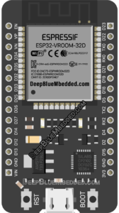
ESP32 DEVKIT v1 DOIT An this is the most popular ESP32 development board that is based on the WROOM-32 module. It’s the most convenient option for learning ESP32 and getting started with developing IoT applications using that chip. This is the one, I’ll be using in all of this course’s LABs (consider getting 2 of these to follow along with this series of tutorials). 30 GPIOs Version: [ Amazon.com – eBay.com – Banggood.com ] 36 GPIOs Version: [ Amazon.com – eBay.com – Banggood.com ] |
 |
Why do I recommend ESP32 DEVKIT v1 DOIT Board?
Because it’s the most affordable, simple, and accessible option out there in the meantime. It gives you the freedom of controlling most of the available GPIO pins without having any “hard-wired” pins to an LCD or something extra on the board itself. It’s just a great option for getting started and following any tutorial online for ESP32. Besides being the recommended option for this series of tutorials (course).
When to consider using other ESP32 dev boards?
If you’re working on a project that needs an on-board battery connector & charger circuitry, or maybe an on-board LCD screen, or an SD card slot, or other hardware board features. All of that will come in handy by switching to another ESP32 board that includes those specific features you’re looking for. However, it comes at the cost of being limit in GPIO pins utilization. As you know, the built-in LCD, SD card, or whatever will have some reserved GPIO pins for that specific functionality. Just be aware of this fact.
ESP32 DevKit Pinout Guide
In this series of tutorials, I’ll be mostly using the ESP32 DevKit DOIT Board (with 32 GPIO pins). It’s what I’d recommend if you’d like to follow along with this series of tutorials. However, any other ESP32 board should also work fine. You’ll only need to change the GPIO pins being used in many of the code examples. ( Check The ESP32 Tutorials Full Hardware Kit )
ESP32 DEVKIT v1 DOIT Pinout
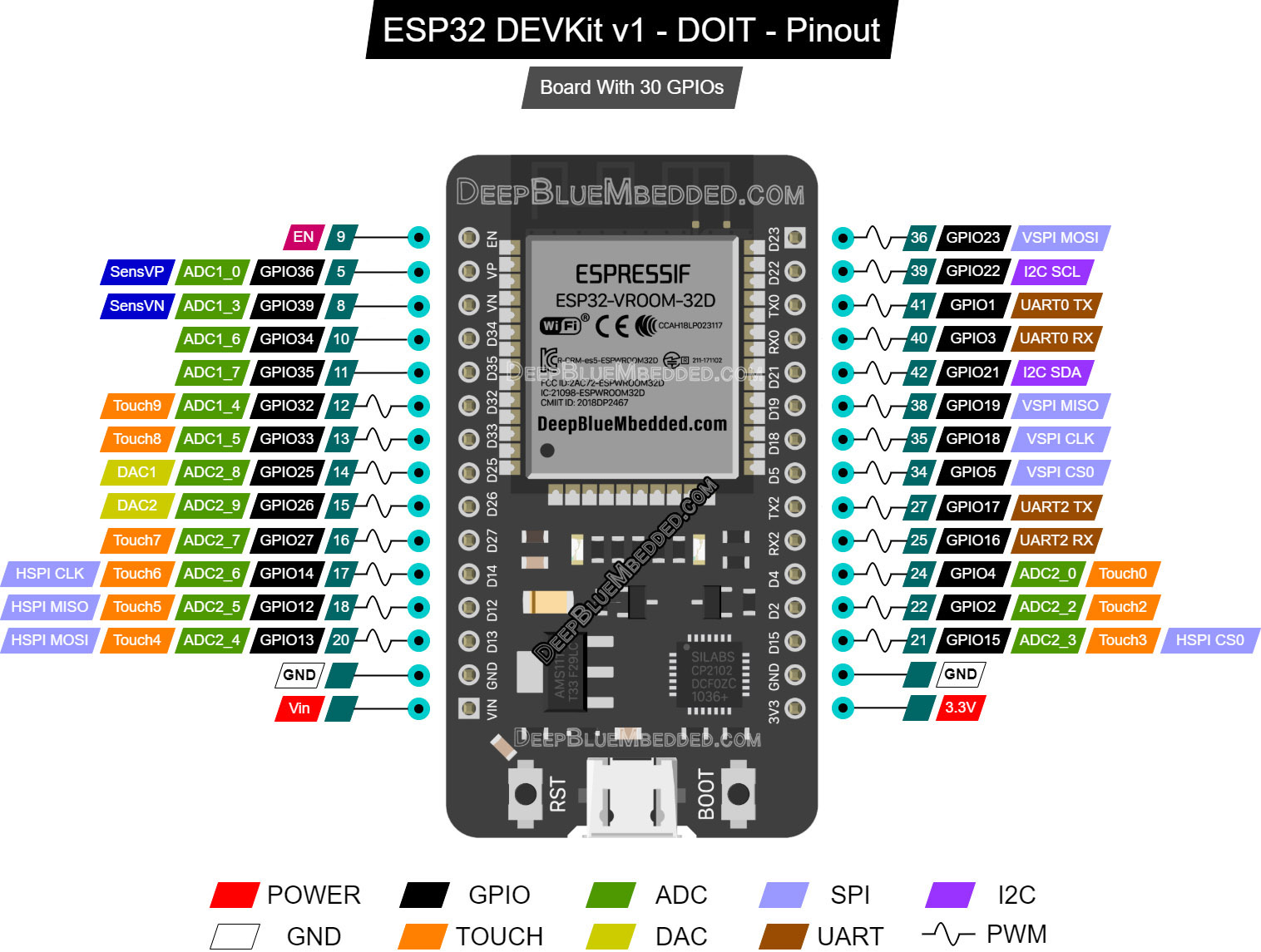
Right-Click the image to view it in a new tab in high resolution if it’s not clear enough in normal view.
Now let’s discuss the ESP32 pins and internal peripherals. Which pins are used for which functions and how to choose the pins to be used in your projects without running into hardware conflicts between the peripherals and their associated GPIO pins.
ESP32 GPIO Pins
All GPIO pins can be configured as inputs or outputs except for 4-pins that are input-only pins. These pins don’t have internal pull-ups or pull-down resistors. We can’t set those pins as outputs, they’re essentially input-only pins (Those are also non-PWM pins):
- GPIO 34
- GPIO 35
- GPIO 36
- GPIO 39
ESP32 PWM Pins
The ESP32 has a PWM LED controller that supports up to 16 channels. You can assign the PWM outputs to any GPIO pins you want, given that those pins can be set as outputs. Some pins are input only hence they don’t support PWM output.
The PWM frequency, resolution, and duty cycle are all programmable. Setting the PWM resolution to 8 bits will give you a PWM DutyCycle range from 0 up to 255. While setting the resolution to 10 bits will give you a DutyCycle range from 0 up to 1023. And so on…
ESP32 ADC Channels
The ESP32 has 18 x 12 bits SAR ADC input channels. The 12-bit ADC will give you conversions in the range [ 0 up to 4095 ]. There are 2 independent ADC converters ADC1, ADC2. The pinout for the analog channel pins is indicated in the diagram above.
ESP32 DAC Channels
The ESP32 chip has 2 x 8 bits DAC channels. Those are the 2 DAC channels:
- DAC1 (GPIO25)
- DAC2 (GPIO26)
ESP32 Interrupt Pins
All GPIO pins can be configured as interrupt sources.
ESP32 TouchPad Pins
There are 9 capacitive touch-sensing channels on the ESP32. A dedicated hardware module to provide capacitive touch sensing capability for your applications. The pinout for the CapTouch pins is indicated in the diagram above.
ESP32 UARTs
The ESP32 has 3 x UART modules, one of them is hard-wired to the USB-TTL converter IC to program (flash) the board with firmware. So we’re left with 2 x UART modules to use UART0 & UART2.
ESP32 SPI
The ESP32 has 4 x SPI interfaces but not all of them are usable. Those are the GPIO pins for the available SPI interfaces:
| VSPI | HSPI | |
| MOSI | GPIO 23 | GPIO 13 |
| MISO | GPIO 19 | GPIO 12 |
| SCK | GPIO 18 | GPIO 14 |
| SS | GPIO 5 | GPIO 15 |
ESP32 I2C
The ESP32 has 2 x I2C Interfaces and any pin can be set as SDA or SCL. While using the ESP32 Arduino Core, the default I2C pins are:
- GPIO 21 (SDA)
- GPIO 22 (SCL)
You can still change the I2C pins to whichever you want using the wire.begin() function.
|
1 |
Wire.begin(SDA_pin, SCL_pin); |
ESP32 Development Framework Options
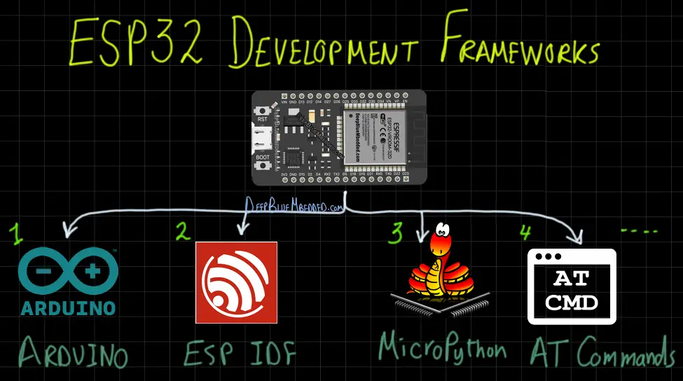
There are a number of different ways that you can use to develop IoT applications with the ESP32 boards. It depends on the level of abstraction and level of control you want to have over the embedded software behavior at the end product. Here are some of the most popular frameworks that are being used with ESP32 hardware to develop firmware applications:
- ESP32 IDF (IoT Development Framework by ESPRESSIF)
- ESP32 Arduino Core
- ESP32 MicroPython
- ESP32 AT Commands
- ESP32 Lua
- ESP32 Javascript
- …
In this series of tutorials, we’ll be using the 2nd option which is ESP32 Arduino core to write C++ code for the ESP32 boards as any of the common Arduino boards. Except for the fact that ESP32 boards have Wi-Fi/BLE enabled, a more powerful processor, and a more rich set of peripherals.
But generally speaking, I’ll be introducing you to all of the first 4 frameworks to develop firmware for ESP32 so check out the Main ESP32 Tutorials Home Page, to access the complete list of tutorials for (ESP32 Arduino – ESP32 IDF – ESP32 AT Commands – ESP32 MicroPython).
1- ESP32 IDF
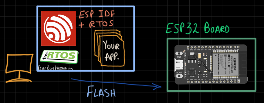
This is the native way of developing IoT projects with ESP32 devices using the official IDF (IoT Development Framework) by Espressif. It gives you complete control over everything in your embedded firmware timing behavior, tasks, priorities, and all real-time measures. The only downside is being way harder than all other methods available for developing ESP32 firmware.
It requires a lot of learning, embedded C coding, RTOS (real-time operating systems) knowledge, and many other things. We’ll be developing applications under the Espressif IDF and RTOS, creating tasks, assigning priorities, ensuring safe shared resources utilization by mutual exclusion & semaphores, and all that stuff.
The majority of the readers here on my website tend to love those things and going too deep in the systems, taking measurements, evaluating and enhancing the performance, and so on. However, in this series of tutorials, we will be using the next method that is more friendly for all readers. Which is the “Arduino Framework”, but you’ll also find another series of tutorials for ESP32 IDF development if you happen to be one of those who love such things. Just check out the Main ESP32 Tutorials Home Page.
2- ESP32 Arduino Core
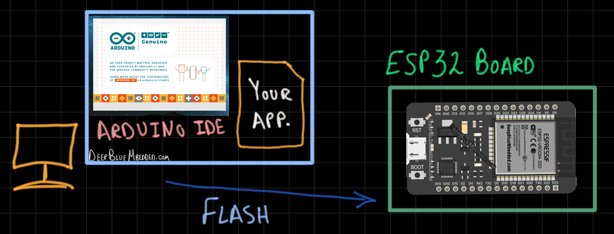
Here we come to the most common method for developing IoT applications with ESP32 devices, the Arduino Framework. We can actually burn the Arduino Core Firmware to ESP32 boards and use them as if they’re usual Arduino boards + Having Wi-Fi / BLE. This means we’ll be using the Arduino IDE, board manager, writing Arduino C++ code, using all community-contributed libraries for Arduinos, and all that cool stuff.
This is a huge advantage for this method of ESP32 development over all other options mentioned here in this section. It’s because of the extraordinary popularity of Arduino, the ease of use, the learning curve, the amazingly active community, and more.
This series of tutorials will be dedicated to walking you through the process of getting started with ESP32 development using the Arduino Framework. By introducing all the important theoretical concepts and putting them into practice by creating so many practical LABs.
3- ESP32 MicroPython
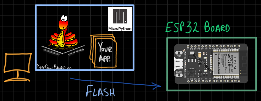
We can also burn the MicroPython firmware for ESP32 on the board, so it becomes Python-Programmable. And you can import the community-contributed Python libraries and use them for building your own applications in Python. Especially for those who love programming in this language. Personally, I don’t xD! But will try making some tutorials for you to get started with ESP32 MicroPython programming.
This method has a very low barrier to getting started and is actually preferred by many makers due to this. You can check the ESP32 MicroPython tutorials series on the Main ESP32 Tutorials Home Page.
4- ESP32 AT Commands
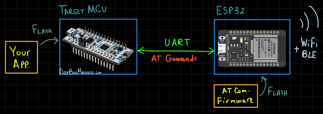
This is the last way of developing IoT applications with ESP32 boards that we’ll be experimenting with as well. Espressif did also develop a pretty extensive set of instructions for the “AT Commands” mode and it’s well-documented. We can burn the AT Commands firmware on the ESP32 board so it becomes a device that can be controlled over UART using the main (target) microcontroller in our application.
You can use Arduino, STM32, PIC, or any other microcontroller that you have got to control the ESP32 using AT Commands. Which adds Wi-Fi / BLE connectivity to your main MCU with very little effort. This method will be discussed in detail in another series of tutorials (check out the Main ESP32 Tutorials Home Page).
Installing ESP32 Arduino Toolchain
So you want to write Arduino code (C++) for your ESP32 development boards and use the tremendous amount of community-contributed libraries for all sorts of modules, sensors, protocols, etc. This takes us to the next step which is to install the toolchain we’ll be using for writing Arduino code (for ESP32 core) and uploading those applications to ESP32 boards.
For this, we need a Compiler, Library Manager, Board Manager, Loader (for flashing the code), Serial Monitor, etc. All of those functionalities are supported by the Arduino standard IDE. However, there are other IDE options that will give you the same features + auto code-completion + debugging + and multi-file multi-project management + version control. So, here is a comparison between the most common IDE options for those who would like to program ESP32 with Arduino code.
Arduino IDE Vs PlatformIO + VS Code
 |
 |
|
| Code Editor | ✔ | ✔ |
| Compiler | ✔ | ✔ |
| Board Manager | ✔ | ✔ |
| Loader (Flasher) | ✔ | ✔ |
| Library Manager | ✔ | ✔ |
| Syntax Highlighter | ✔ | ✔ |
| Serial Monitor | ✔ | ✔ |
| Auto Code-Completion | ✔ | |
| Debugger | ✔ | |
| Multi-Project | ✔ | |
| Version Control | ✔ |
You can use any of the IDE options to follow along with this series of tutorials. I’d recommend going for the Arduino IDE which is a very beginner-friendly option. However, it’s your call, just use whatever suits your needs for developing your applications/projects. Follow the guides down below to install the toolchain for both IDE options:
- Installing Arduino IDE For ESP32 Development
- Installing VS Code + PlatformIO For ESP32 Arduino Development
* At the time of writing this tutorial, Arduino developers are working on Arduino IDE V2.0 which promises to have a live debugger, auto code-completion, and some other features. It’s now in BETA and may be a good option in the future for you to consider as well.
ESP32 LED Blinking
Hardware
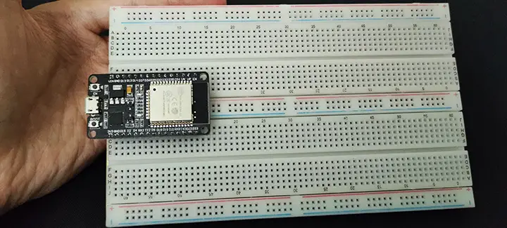
As you can see in the picture down below, the ESP32 DevKit board is barely fitting in the breadboard leaving no room for us to connect anything on the board. That’s why we should consider changing the structure of the breadboard itself as shown hereafter.
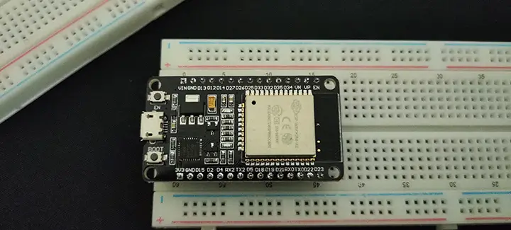
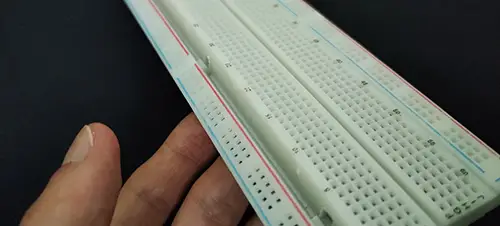
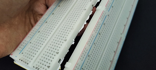
You can easily snap any of the power rails on the breadboard and cut it out with a cutting knife, then plug in another breadboard. Therefore, in total, we’ll be using 2 breadboards for the ESP32 dev board. This will secure enough headroom for us to connect external sensors, modules, custom circuitry, etc.
 |
 |
The final breadboard setup will look like this shown below. This setup will help us in the future LAB examples to connect external modules, sensors, and other electronics without having to re-configure anything on the hardware level. Also, note that the USB port is pointing outwards so it’s easy to plug it in and out for firmware flashing.
The working space is on the right side of the ESP32 board. If it’s populated with electronics, it’s definitely will, then you’ll have some hard time plugging in/out the USB port if the board is placed in reverse.
ESP32 Blinking LED Code Example
This is the LED blinking code example for ESP32 to blink the onboard LED which is connected to GPIO pin 2. We’ll turn it ON for 250ms and OFF for another 250ms and keep repeating.
|
1 2 3 4 5 6 7 8 9 10 11 12 13 14 |
#define LED_BUILTIN 2 // On-Board LED Pin void setup() { // initialize digital pin LED_BUILTIN as an output. pinMode(LED_BUILTIN, OUTPUT); } // the loop function runs over and over again forever void loop() { digitalWrite(LED_BUILTIN, HIGH); // turn the LED on (HIGH is the voltage level) delay(250); digitalWrite(LED_BUILTIN, LOW); // turn the LED off by making the voltage LOW delay(250); } |
Choose the board, COM port, hold down the BOOT button, click upload and keep your finger on the BOOT button pressed. When the Arduino IDE starts sending the code, you can release the button and wait for the flashing process to be completed.
Now, the ESP32 is flashed with the new firmware that won’t start working until the next reset operation. So, every time you upload a new code to the board, press the EN button to reset the board. After reset and during the booting process, it’ll load the new firmware and start executing the code. (This step may not be needed in new versions of ESP32 Arduino Core)
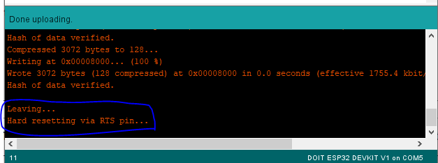
Note: After uploading the code to the microcontroller, the Arduino IDE log had this message shown below. Which appears to be a hardware reset by order of the loader tool in Arduino IDE. This eliminated the need to manually restart the ESP32 board (by pressing the EN button) after uploading any new firmware in order to run that new code. (This note was taken with ESP32 Arduino Core v1.0.6)
Demo Video For The Result
Did you find this helpful? If yes, please consider supporting this work and sharing these tutorials!
Stay tuned for the upcoming tutorials and don’t forget to SHARE these tutorials. And consider SUPPORTING this work to keep publishing free content just like this!
| ESP32 Course Home Page ???? | |||||||
| Previous Tutorial | Tutorial 0 | Next Tutorial | |||||
This is the ultimate guide for ESP32 WiFi, if you’re just starting with ESP32 WiFi, you should definitely check it out. It’ll provide you with a clear roadmap for what to learn and in which order to fully understand everything about ESP32 WiFi.

Amazing! Keep it up looks so promising
Thanks, Rob!
I’ve been following your STM32 tutorials and it’s by far the best I’ve ever seen online
This looks like an amazing timing to get started in IOT, thanks for sharing!
I’ll get back to resume STM32 tutorials in the near future of course.
Let’s just get some more ESP32 tutorials done, and I’ll keep juggling thereafter xD!
You’ve got a UNIQUE teaching style, deserves all the support and much love
i’ll be following this ESP32 series. keep up the good work!
Regards
Oh, Thanks so much for your kind words ^^
Kind regards,