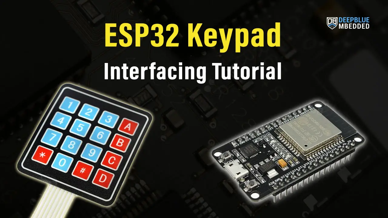
This is a comprehensive guide for ESP32 Keypad interfacing. You’ll learn how to use ESP32 Keypad Matrix with Arduino IDE. We’ll create a few examples to practice the subject and you will modify the examples to achieve what’s needed in your project. The first example will show you how to interface ESP32 with both 4×4 and 4×3 Keypad, then use Keypad with LCD, and finally, we’ll create an electronic lock password-based system with ESP32 keypad and LCD.
The ESP32 Keypad Application Examples That We’ll Create in This Tutorial Are As Follows:
- ESP32 Keypad interfacing Demo Example For 4×4 and 3×4 Keypad Matrix
- ESP32 Keypad LCD Example (With i2c LCD)
- ESP32 Keypad Lock Password-Based System
Table of Contents
- ESP32 Keypad Interfacing
- ESP32 Keypad Library (Arduino Core)
- ESP32 Keypad Example Code (Arduino Core)
- ESP32 Keypad LCD Example (I2C LCD)
- ESP32 Keypad Lock Password Example
- Download Attachments
- Concluding Remarks
ESP32 Keypad Interfacing
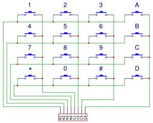
A keypad is a matrix of buttons connected in rows and columns to form the whole unit. In software, we scan through the rows and columns pins on the microcontroller in order to decide which key on the keypad is pressed by the user. And here is a clear diagram of how the keypad looks internally.
And this is the keypad pinout.
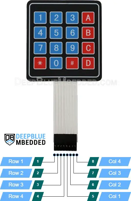
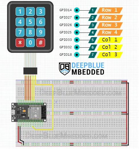
For the 4×4 Keypad, there are 8 pins (4 rows and 4 columns). And for the 4×3 Keypad, there are 6 pins (4 rows and 3 columns).
Here is how to connect ESP32 with Keypad 4×4 and 4×3.
ESP32 Keypad 4×4 Wiring Diagram
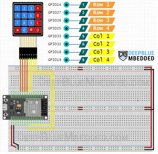
ESP32 Keypad 4×3 Wiring Diagram
ESP32 Keypad Library (Arduino Core)
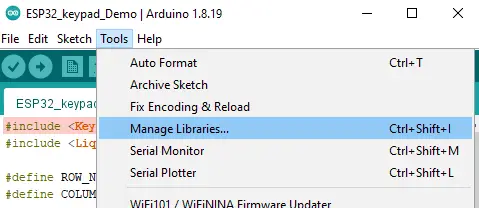
You need to install the Keypad library for the ESP32 Arduino core first before you’re able to use it, unlike the built-in Arduino Keypad library. But it’s rather simple to do, just open the library manager from the tools menu.
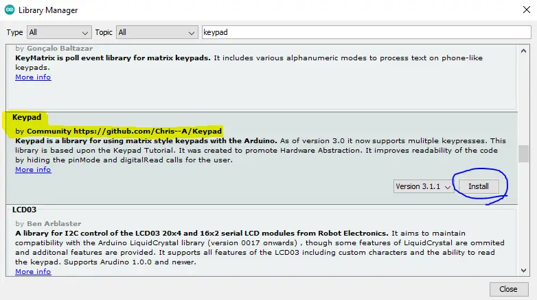
Then, search for this keypad library and click install.
Now, you can use the Keypad library in any project by including the library header file as shown below.
|
1 |
#include <Keypad.h> |
You need to specify the number of rows and columns in your keypad (For a 4×4 matrix it’s 4 rows and 4 columns) and similarly any other variant of membrane keypads. This is done by the following definitions.
|
1 2 |
#define ROWS 4 #define COLS 4 |
Then, you should create a keyMap with the characters that correspond to each key on the keypad. This is done by defining a two-dimensional array as shown below.
|
1 2 3 4 5 6 |
char keyMap[ROWS][COLS] = { {'1','2','3', 'A'}, {'4','5','6', 'B'}, {'7','8','9', 'C'}, {'*','0','#', 'D'} }; |
Next, we need to select the GPIO pins that we’ll use for connecting the keypad pins. The rows’ pins as well as the columns’ pins, which can be done by defining the following two arrays.
|
1 2 |
uint8_t rowPins[ROWS] = {14, 27, 26, 25}; // GIOP14, GIOP27, GIOP26, GIOP25 uint8_t colPins[COLS] = {33, 32, 18, 19}; // GIOP33, GIOP32, GIOP18, GIOP19 |
Now, we need to create an instance of the Keypad and pass to it all the information that we’ve defined earlier.
|
1 |
Keypad keypad = Keypad(makeKeymap(keyMap), rowPins, colPins, ROWS, COLS ); |
And that’s all about it. Whenever you need to read the keypad status, call this function as shown below, and it’s going to return the equivalent character for the key that’s currently pressed by the user.
|
1 |
char key = keypad.getKey(); |
And we’ll test this out in the following examples hereafter in this tutorial.
Some Useful APIs (Functions) in The Keypad Library
Here is a brief for some of the useful functions in the Keypad library that you may need to use in your project.
- setDebounceTime(unsigned int time) sets the number of milliseconds the keypad will wait until it accepts a new keypress/key event.
- KeyState getState() returns the current state of any of the keys. The four states are IDLE, PRESSED, RELEASED, and HOLD.
- setHoldTime(unsigned int time) sets the number of milliseconds the user will have to hold a button until the HOLD state is triggered.
- addEventListener(keypadEvent) triggers an event if the keypad is clicked on. You pass your callback function handler to it.
- boolean keyStateChanged() lets you know when the key has changed from one state to another. instead of polling for a key state, you can get if it’s changed or not.
- char waitForKey() waits forever until someone presses a key. Be advised that this is a blocking routine that may mess up your system timing behavior or cause unexpected delays.
ESP32 Keypad Example Code (Arduino Core)
Here are two examples to test the ESP32 Keypad library functionality with both a 4×4 keypad matrix and a 4×3 keypad matrix. You can modify the code to achieve any different functionality that you want.
In the examples below, clicking on any key on the keypad will trigger a serial write operation for the equivalent character of the key that’s held down by the user. Just a very simple application to test that everything is running ok as we expect it to.
ESP32 Keypad 4×4 Example
|
1 2 3 4 5 6 7 8 9 10 11 12 13 14 15 16 17 18 19 20 21 22 23 24 25 26 27 28 29 30 31 32 33 34 |
/* * LAB Name: ESP32 Keypad Demo Example (4x4) * Author: Khaled Magdy * DeepBlueMbedded 2023 * For More Info Visit: www.DeepBlueMbedded.com */ #include <Keypad.h> #define ROWS 4 #define COLS 4 char keyMap[ROWS][COLS] = { {'1','2','3', 'A'}, {'4','5','6', 'B'}, {'7','8','9', 'C'}, {'*','0','#', 'D'} }; uint8_t rowPins[ROWS] = {14, 27, 26, 25}; // GIOP14, GIOP27, GIOP26, GIOP25 uint8_t colPins[COLS] = {33, 32, 18, 19}; // GIOP33, GIOP32, GIOP18, GIOP19 Keypad keypad = Keypad(makeKeymap(keyMap), rowPins, colPins, ROWS, COLS ); void setup(){ Serial.begin(115200); } void loop(){ char key = keypad.getKey(); if (key) { Serial.println(key); } } |
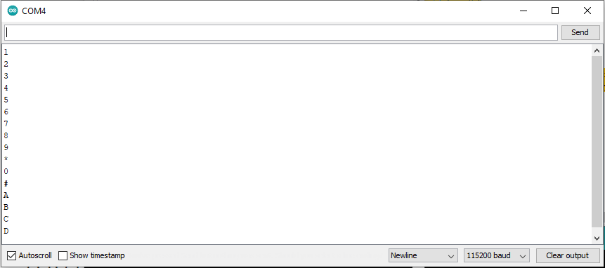
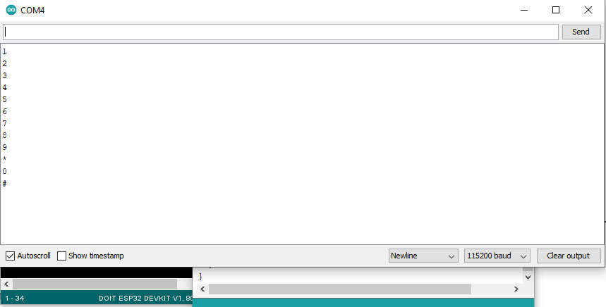
Here is what the output looks like on the serial monitor. I’ve tried all the keys and it’s working as expected.
ESP32 Keypad 4×3 Example
|
1 2 3 4 5 6 7 8 9 10 11 12 13 14 15 16 17 18 19 20 21 22 23 24 25 26 27 28 29 30 31 32 33 34 |
/* * LAB Name: ESP32 Keypad Demo Example (4x3) * Author: Khaled Magdy * DeepBlueMbedded 2023 * For More Info Visit: www.DeepBlueMbedded.com */ #include <Keypad.h> #define ROWS 4 #define COLS 3 char keyMap[ROWS][COLS] = { {'1','2','3'}, {'4','5','6'}, {'7','8','9'}, {'*','0','#'} }; uint8_t rowPins[ROWS] = {14, 27, 26, 25}; // GIOP14, GIOP27, GIOP26, GIOP25 uint8_t colPins[COLS] = {33, 32, 18}; // GIOP33, GIOP32, GIOP18 Keypad keypad = Keypad(makeKeymap(keyMap), rowPins, colPins, ROWS, COLS ); void setup(){ Serial.begin(115200); } void loop(){ char key = keypad.getKey(); if (key) { Serial.println(key); } } |
And here is the output on the serial monitor, as you can see all the keys are working just as fine.
ESP32 Keypad LCD Example (I2C LCD)
In this example, we’ll add an LED to the project and it’s going to display the text written using the keypad instead of using the serial monitor. We’ll be using the I2C version of the alphanumeric LCD 16×2 because it’s the most efficient way to do it in terms of GPIO pins utilization. All the keys’ characters will be displayed on the LCD except for the “D” key, we’ll program it to be a “Clear Screen” button instead.
The screen shall also be cleared whenever we reach the 16th character which is the limit per line of characters.
Wiring
Here is how to hook up the ESP32 with i2C LCD and Keypad.
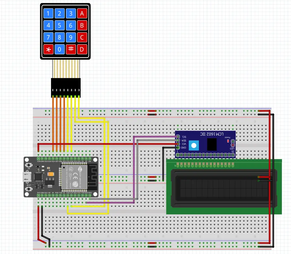
| ESP32 GPIO Pin | Connect To |
| GPIO14 | Row1 |
| GPIO27 | Row2 |
| GPIO26 | Row3 |
| GPIO25 | Row4 |
| GPIO33 | Col1 |
| GPIO32 | Col2 |
| GPIO18 | Col3 |
| GPIO19 | Col4 |
| GPIO22 | SCL |
| GPIO21 | SDA |
Example Code
Here is the full code listing for this example project.
|
1 2 3 4 5 6 7 8 9 10 11 12 13 14 15 16 17 18 19 20 21 22 23 24 25 26 27 28 29 30 31 32 33 34 35 36 37 38 39 40 41 42 43 44 45 46 47 48 49 50 51 52 53 54 55 |
/* * LAB Name: ESP32 Keypad + I2C LCD * Author: Khaled Magdy * DeepBlueMbedded 2023 * For More Info Visit: www.DeepBlueMbedded.com */ #include <Keypad.h> #include <Wire.h> #include <LiquidCrystal_I2C.h> #define ROWS 4 #define COLS 4 char keyMap[ROWS][COLS] = { {'1','2','3', 'A'}, {'4','5','6', 'B'}, {'7','8','9', 'C'}, {'*','0','#', 'D'} }; uint8_t rowPins[ROWS] = {14, 27, 26, 25}; // GIOP14, GIOP27, GIOP26, GIOP25 uint8_t colPins[COLS] = {33, 32, 18, 19}; // GIOP33, GIOP32, GIOP18, GIOP19 uint8_t LCD_CursorPosition = 0; Keypad keypad = Keypad(makeKeymap(keyMap), rowPins, colPins, ROWS, COLS ); LiquidCrystal_I2C I2C_LCD(0x27, 16, 2); // set the LCD address to 0x27 for a 16 chars and 2 line display void setup(){ Serial.begin(115200); // Initialize The I2C LCD I2C_LCD.begin(); // Turn ON The Backlight I2C_LCD.backlight(); // Clear The Display I2C_LCD.clear(); } void loop(){ char key = keypad.getKey(); if (key) { Serial.print(key); I2C_LCD.setCursor(LCD_CursorPosition++, 0); if(LCD_CursorPosition == 16 || key == 'D') { I2C_LCD.clear(); LCD_CursorPosition = 0; } else { I2C_LCD.print(key); } } } |
Testing Results
This is a quick demo showing the testing results for this example project.
ESP32 Keypad Lock Password Example
This is a simple password-based lock system with ESP32 Keypad + I2C LCD. The password is a 6-char string and the user is allowed to enter 6 numbers only. if the password is correct, we’ll print “Access Granted!” to the LCD. If it’s not correct, we’ll print “Wrong PassWord!”. The ‘D’ key is used for clearing the display and re-try.
Wiring
Exactly the same as the previous example.
Example Code
Here is the full code listing for this example project.
|
1 2 3 4 5 6 7 8 9 10 11 12 13 14 15 16 17 18 19 20 21 22 23 24 25 26 27 28 29 30 31 32 33 34 35 36 37 38 39 40 41 42 43 44 45 46 47 48 49 50 51 52 53 54 55 56 57 58 59 60 61 62 63 64 65 66 67 68 69 70 71 72 73 74 75 |
/* * LAB Name: ESP32 Keypad Password Lock * Author: Khaled Magdy * DeepBlueMbedded 2023 * For More Info Visit: www.DeepBlueMbedded.com */ #include <Keypad.h> #include <Wire.h> #include <LiquidCrystal_I2C.h> #define ROWS 4 #define COLS 4 char keyMap[ROWS][COLS] = { {'1','2','3', 'A'}, {'4','5','6', 'B'}, {'7','8','9', 'C'}, {'*','0','#', 'D'} }; uint8_t rowPins[ROWS] = {14, 27, 26, 25}; // GIOP14, GIOP27, GIOP26, GIOP25 uint8_t colPins[COLS] = {33, 32, 18, 19}; // GIOP33, GIOP32, GIOP18, GIOP19 uint8_t LCD_CursorPosition = 0; String PassWord = "134679"; String InputStr = ""; Keypad keypad = Keypad(makeKeymap(keyMap), rowPins, colPins, ROWS, COLS ); LiquidCrystal_I2C I2C_LCD(0x27, 16, 2); // set the LCD address to 0x27 for a 16 chars and 2 line display void setup(){ Serial.begin(115200); // Initialize The I2C LCD I2C_LCD.begin(); // Turn ON The Backlight I2C_LCD.backlight(); // Clear The Display I2C_LCD.clear(); I2C_LCD.setCursor(0, 0); I2C_LCD.print("Enter PassWord:"); } void loop(){ char key = keypad.getKey(); if (key) { InputStr += key; I2C_LCD.setCursor(LCD_CursorPosition++, 1); if(LCD_CursorPosition == 6) { String message; if(InputStr == PassWord) { message = "Access Granted!"; } else { message = "Wrong PassWord!"; } InputStr = ""; I2C_LCD.clear(); LCD_CursorPosition = 0; I2C_LCD.print(message); } else if(key == 'D') { InputStr = ""; I2C_LCD.clear(); LCD_CursorPosition = 0; I2C_LCD.print("Enter PassWord:"); } else { I2C_LCD.print(key); } } } |
Testing Results
This is a quick demo showing the testing results for this example project.
Parts List
Here is the full components list for all parts that you’d need in order to perform the practical LABs mentioned here in this article and for the whole ESP32 series of tutorials found here on DeepBlueMbedded. Please, note that those are affiliate links and we’ll receive a small commission on your purchase at no additional cost to you, and it’d definitely support our work.
Download Attachments
You can download all attachment files for this Article/Tutorial (project files, schematics, code, etc..) using the link below. Please consider supporting my work through the various support options listed in the link down below. Every small donation helps to keep this website up and running and ultimately supports our community.
Concluding Remarks
In conclusion, keypads can be used for so many applications and we’ll definitely address some of them in future tutorials. A better version of the password-based lock system can be built using NVS (non-volatile storage) in the ESP32 in order to save new passwords that the user can input into the system in order to be truly flexible, not hard-coded.
The password should be stored in a memory that’s not whipped out when the controller’s power goes OFF, which is a typical application where you need to use the NVS of the ESP32. To learn more about ESP32 NVS check the following tutorials that cover all possible options to store and retrieve data to/from the ESP32 Non-Volatile Storage.
- ESP32 EEPROM Tutorial
- ESP32 Flash Memory (External SPI Flash) Tutorial
- ESP32 Preferences Flash Memory Tutorial
