High-Resolution (16-Bit) PWM Using CCP Compare & Timer1 Module
In this article, I’d like to introduce you to such an amazing technique that you can implement on a small 8-Bit microcontroller, which will push the hardware CCP PWM module beyond its fundamental limits in terms of resolution. A 10-Bit PWM module can be enhanced using this technique to reach up to 16-Bit in resolution and that’s obviously insane, especially for control systems applications where high-precision is a necessity.
Without further ado, let’s get right into it!
Prerequisites
[toc]
The Mechanics of This Technique
Typical Configurations
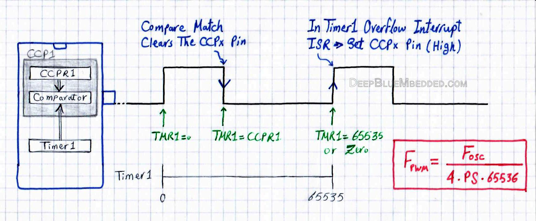
First of all, we’ll be using a 16-Bit Timer module (Timer1) and a CCPx module in compare mode (CCP1).
Timer1 is configured to operate in timer mode, with specific frequency & Prescaler settings. Counting starts from 0 up to 65535. And timer interrupt on overflow should be also enabled! This will define the final PWM Frequency
CCP1 is configured to operate in compare mode, with CCPR1 register pair (16-bit) is preloaded with a value that will determine the final PWM Duty Cycle. The CCP compare mode should be configured to take the following action: drive LOW the CCP1 pin on compare match event.
PWM Signal Generation
1 Timer1 is constantly compared against the value in the CCPR1 register pair. When a match occurs, the CCPx pin will be driven LOW (by hardware).
2 When Timer1 reaches the overflow state (at 65535), in the ISR you should drive HIGH the CCP1 pin (by software).
Step1 -> defines the Duty Cycle of the resulting PWM signal
Step2 -> defines the frequency of the resulting PWM signal
Therefore, we’ll end up having a PWM signal with a 16-Bit of resolution to precisely control its duty cycle. And the possible output frequencies are as follows (using the formula below)
![]()
This means: using Fosc=48MHz, the resulting possible Fpwm options are { 183.1Hz, 91.5Hz, 45.8Hz, 22.9Hz }. For different options of Prescaler values (1, 2, 4, or 8).
Obviously this isn’t very useful for almost any situation, even with a 16-Bit of resolution! we still need to somehow control the frequency of the PWM signal. Consider motor control applications for example (e.g. servo motors or so) which need specific frequency for the PWM signal (e.g. 50Hz or so). That’s what we’ll discuss in a moment.
How To Control The PWM Output Frequency?
Well, it turns out to be the timer preloading technique is a good fit for this situation. You can check out that article if you’ve not yet. And by preloading the Timer1 module it’ll start counting from a specific value (not zero) up to the 65535 maximum limit. This results in a flexible precise control over the output PWM frequency, which will, therefore, follow the equation down below.
![]()
Now, you can vary the Prescaler value and start counting from the value TMR1 instead of zero, to find yourself nearly able to get whatever output frequency value you want. Consider the examples down below:
ex1) using an Fosc=48MHz, what configurations would you set to get an output FPWM of 100Hz?
well, I’d try a high Prescaler at first. let prescaler=2 and solve the above equation in TMR1 value. Which will be 5536. That’s it! just preload the Timer1 module with this value and set Prescaler to 2 and you’ll get a 100Hz PWM output.
ex2) using an Fosc=48MHz, what configurations would you set to get an output FPWM of 2kHz?
well, I’d try a reasonably low Prescaler at first. let prescaler=1 and solve the above equation in TMR1 value. Which will be 59536. That’s it! just preload the Timer1 module with this value and set Prescaler to 1 and you’ll get a 2kHz PWM output.
Note that: by implementing timer preloading, you’ll end up having a controllable output frequency. But the Duty Cycle control rule will now change. Before preloading, it was a little bit more straight forward. You just had to write the value you want (from 0 up to 65535) in the CCPR1 register pair and that’s it. But now, the value to be written in the CCPR1 register must be in the range (from TMR1 up to 65535).
Note Also: a 100% or 0% duty cycle is not easily achievable by using this technique. But it’s not impossible to get as near as you can.
Implementation Steps For This Technique
Procedure
1 Decide on the required Fpwm for your application and use the formula below to choose the convenient Prescaler option for you and work out the preload value as well.
![]()
2 Configure the CCPx pin to be an output pin.
3 Configure the CCPx module to operate in Compare mode with drive LOW to CCPx pin on compare match event.
4 Configure the Timer1 module (or any 16-bit timer) with the specific Prescaler and preload it with TMR1 value from the equation in step1. And also enable the timer overflow interrupt.
5 On each timer overflow interrupt, drive the CCPx pin High and preload the timer with the value you got in step1.
6 Change the duty cycle as you want by writing to the CCPRx register pair. For a 0% duty cycle, you should set it to the timer preload value (the initial counting value) and for a theoretical 100% duty cycle, you should set the CCPRx register pair to 65535. And any Duty Cycle (DC) ratio in between can be obtained by mapping!
PWM General Example – LAB
This quick LAB showcases the technique which we’ve discussed in this article. Here I’m using Fosc=48MHz, and I wanna get a 100Hz PWM output signal. So, by using the formula below & assuming prescaler=2, solve for TMR1 to get the preload value
![]()
100 = 48000000 / 4 x 2 x (65536-TMR1)
TMR1 = 5536 ( The Value To Be Preloaded in the Timer1 Register Pair)!
Therefore, the duty cycle full range starts from 5536 up to 65535. This means you’ve got 60000 levels of resolution for the duty cycle. Do you want to find out how many bits of resolution it equals to?
Well, resolution = log2(60000) = 15.87 bits (very close to 16-bits)
And here is the code for you to check out and you can also make your own adjustments to meet your application design requirements.
Code Listing
|
1 2 3 4 5 6 7 8 9 10 11 12 13 14 15 16 17 18 19 20 21 22 23 24 25 26 27 28 29 30 31 32 33 34 35 36 37 38 39 40 41 42 43 44 45 46 47 48 49 50 51 52 53 54 55 56 57 58 59 60 61 62 63 64 65 66 67 68 69 70 71 72 73 74 75 76 77 78 79 80 81 82 83 84 85 86 87 |
/* * File: main.c * Author: Khaled Magdy * LAB: High-Resolution (16-Bits) PWM (CCP Compare + Timer) */ #include <xc.h> #include "config.h" #include <stdint.h> #define _XTAL_FREQ 48000000 #define PreLoad 5536 #define PWM1 RC2 #define PWM1_D TRISC2 void TMR1_Init(); void CCP_COMP_Init(); void PWM1_16Bit_DC(uint16_t DC); void main(void) { TMR1_Init(); CCP_COMP_Init(); while(1) { // Sweep Over The Full DutyCycle Range // From PreLoad Value 5536 Up To 65535 // Incremental Sweep for(uint16_t i=PreLoad; i<65535; i++) { PWM1_16Bit_DC(i); __delay_us(50); } // Decremental Sweep for(uint16_t i=65535; i>PreLoad; i--) { PWM1_16Bit_DC(i); __delay_us(50); } } return; } //=========================================== //-----------------[ ISR ]------------------- void __interrupt() ISR() { if(TMR1IF) { CCP1CON = 0x00; PWM1 = 1; // Drive CCPx Pin HIGH CCP1CON = 0x09; TMR1IF = 0; TMR1 = PreLoad; // Timer1 Preloading } } //=========================================== void TMR1_Init(void) { // -- [[ Configure Timer1 To Operate In Timer Mode ]] -- // PreLoad Timer1. To start counting from 35536 TMR1 = PreLoad; // Choose the local clock source (timer mode) TMR1CS = 0; // Choose the desired prescaler ratio (1:2) T1CKPS0 = 1; T1CKPS1 = 0; // Switch ON Timer1 Module! TMR1ON = 1; // -- [[ Interrupts Configurations ]] -- TMR1IE = 1; // Timer1 Interrupt Enable Bit TMR1IF = 0; // Clear The Interrupt Flag Bit PEIE = 1; // Peripherals Interrupts Enable Bit GIE = 1; // Global Interrupts Enable Bit } void CCP_COMP_Init() { CCP1CON = 0x09; // Compare Mode & Clear CCP Pin On Match! CCP1IE = 0; PWM1_D = 0; CCPR1 = PreLoad; } void PWM1_16Bit_DC(uint16_t DC) { if(DC >= PreLoad) CCPR1 = DC; } |
Results On Scope
The period is exactly 10ms and the frequency output is exactly 100Hz as what we’ve designed for!
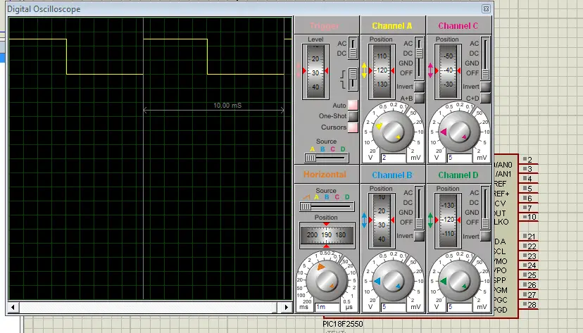
And the duty cycle sweep is very clean and extremely rich in the number of levels about 60000 of discrete DC levels. Here is an animation for it
PWM DC Sweep From 50% Up to To 51% – LAB
This quick LAB is intended to highlight how accurate the duty cycle can be using the proposed technique in this article. In the main function, I’ll perform a duty cycle sweep from 50% DC up to 51% DC. And let you see how deep we can go & precisely set the duty cycle to whatever we want.
This may not be useful for some applications but for others, it’s just an amazing feature to have.
Code Listing
|
1 2 3 4 5 6 7 8 9 10 11 12 13 14 15 16 17 18 19 20 21 22 23 |
void main(void) { TMR1_Init(); CCP_COMP_Init(); while(1) { // Sweep TheDutyCycle From 50% Up To 51% // Incremental Sweep for(uint16_t i=35535; i<36135; i++) { PWM1_16Bit_DC(i); __delay_ms(1); } // Decremental Sweep for(uint16_t i=36135; i>35535; i--) { PWM1_16Bit_DC(i); __delay_ms(1); } } return; } |
Results On Scope
Sweeping From 50% To 51% Duty Cycle. There are nearly 600 Discrete Levels Between Them!
Test On Real Target MCU & My DSO
“Using The Zoom Function”
Needed Components For The Above LABs
| Qty. | Component Name | Buy On Amazon.com |
| 1 | PIC18F2550 | Add |
| 1 | BreadBoard | Add |
| 1 | LED | Add Add |
| 1 | Resistors Kit | Add Add |
| 1 | Capacitors Kit | Add Add |
| 1 | Jumper Wires Pack | Add Add |
| 1 | LM7805 Voltage Regulator (5v) | Add |
| 1 | Crystal Oscillator | Add |
| 1 | PICkit2 or 3 Programmer | Add |
| 2 | 9v Battery or DC Power Supply | Add Add Add |
My DSO Siglent-SDS1104 (on Amazon.com)
My Function Generator Fy-6900 (on Amazon.com)
*Affiliate Links Disclosure: links will make me a small commission at no additional cost to you*
The Prototyping Board Setup Tutorial
At the end of this article, I hope you’ve learned something new. And if you don’t have an application in mind that can benefit from this high-resolution PWM technique, then stay tuned for the Servo Motor Control Tutorial – PART3. As it’s going to be implemented using the proposed technique in this article to obtain a very precise servo control over the angular position.
If you like this article, hit the like button and please support this work by sharing it on social networks! That keeps me motivated for publishing more articles and tutorials. Cheers ^^
Ben fatto e di facile comprensione…complimenti spiegato così si possono raggiungere ottimi livelli.
Ciao e un grazie
Hi,
Thanks for the great tutorial. Can I use this technique on 16F877A?