| Previous Tutorial | Tutorial 20 | Next Tutorial | |||||
| UART TTL-USB Converter Tutorial | |||||||
| Introductory Level ★☆☆☆☆ | |||||||
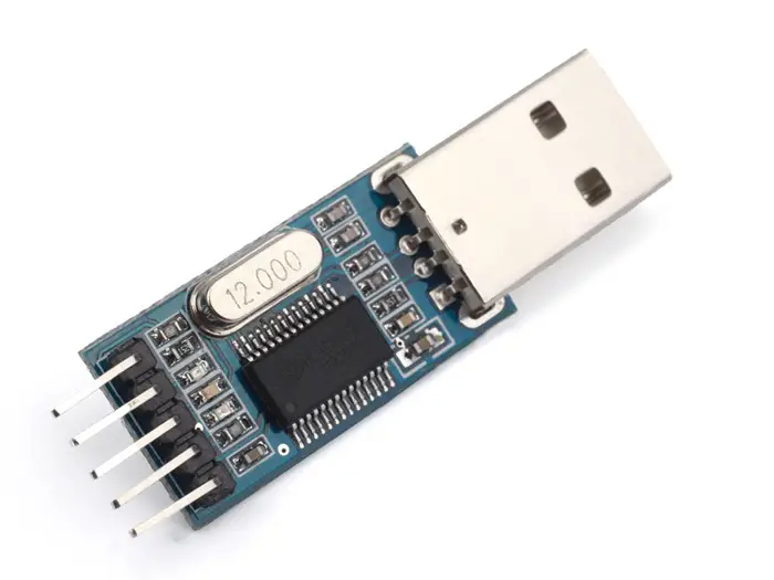
In this tutorial, you’ll learn how to create a communication channel between your PC & the Microcontroller via UART serial port. We’ll be using a serial USB-To-TTL converter module as we can’t just hook the RX/TX pins to the D+/D- pins of a USB Port. We’ll develop the required firmware/software in order to configure the MCU for data transmission, and our PC for receiving & monitoring data respectively. So let’s get started!
[toc]
Components Needed For This Tutorial
| Quantity | Component Name |
| 1 | PIC16F877A |
| 1 | Breadboard |
| 1 | Jumper Wires Pack |
| 1 | USB-TTL Converter |
| 2 | LEDs |
| 2 | 330Ω Resistors |
| 1 | 4MHz Crystal OSCillator |
| 1 | LM7805 Voltage Regulator |
| 1 | 9v Battery or any Power Supply Source |
| 1 | PICkit3 (PIC Programmer) |
Preface
As you might have learned in the C-programming class/course, for inspecting (checking) the value of any variable in your program you’ll just pass it to the printf() function and it’ll get displayed on the console screen of your computer. The process is as follows: A variable in the RAM of the PC is sent to the display device (screen) of the same computer. Just as simple as it seems to be!
However, in the Embedded-C programming, you just can’t do that. Despite having your variables stored in the RAM, you still have no way to display them other than using the parallel/serial ports. Using the parallel IO ports is kind of inefficient way to do so as you’ll be unnecessarily using a whole bunch of IOs & still getting binary output which may not make that much of sense in many situations.
The parallel IO ports can still be used to display your data in a more convenient way such as 7-segments display as we’ve discussed earlier in this course. Or even the alphanumeric LCDs as we’ll see in the upcoming tutorials.
On the other hand, the serial ports provide a convenient way to shift out your data from the RAM to another device that can display it (e.g. Desktop, Laptop, Serial LCDs, etc). And that’s what we’re going to do in this tutorial.
Having the ability to do so, will help you debug your code, provide visual UX for your projects, and much more.
UART Quick Review
If you’re following this series of tutorials, you should have completed the UART demo tutorial. If not, you can check it out using the link down below (disclaimer: it’s a very long read & it’s worth it!)
At the end of the UART tutorial, you’ll have developed your own version of the following functions: UART_Init() and UART_TX()
For those who came from an Arduino background, the UART tutorial should have guided you through the process of creating your own version of the Serial.begin() and Serial.print() similar functions.
The Arduinos have their on-board USB-TTL UART converters so they don’t usually run into the process of hooking this external module.
Hereafter, we’ll hook that converter to our bare PIC microcontroller and send some data using our Serial.print() function aka UART_TX()
But first of all, we’ll have a deeper insight into the USB-TTL UART converter chip.
USB-TTL Converter Module

Brief Description
The PL-2303 chip provides a convenient solution for connecting a UART-like full-duplex asynchronous serial device to any Universal Serial Bus (USB) capable host. The PL-2303 highly compatible drivers could successfully simulate generic COM ports on most operating systems.
By taking advantage of USB Bulk Transfer Mode, large data buffers, and automatic flow control, The PL-2303 is capable of achieving higher throughput. When real RS232 signaling is not required, baud rate higher than 115200 bps could be used for even higher performance. The flexible baud rate generator of PL-2303 could be programmed to generate any rate between 75 bps to 12M bps.
PL-2303 is exclusively designed for mobile and embedded solutions in mind, providing a small footprint that could easily fit into any small PCB layouts. With very small power consumption in either operating or suspend mode.
Here is the Functional Block Diagram of the PL-2303 Chip.
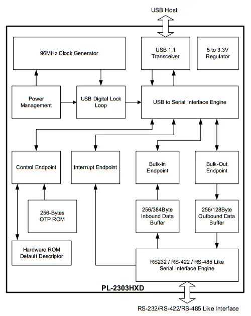
For more information visit the manufacturer website @ www.prolific.com
Pinout & Connection Diagram
The function of each one of the 5-pins on this module’s board is labeled on the back side as shown in the following picture.
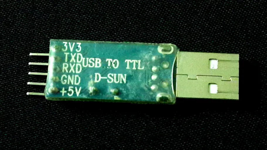
- 3.3v pin (if your MCU device’s TTL logic is running at 3.3v level).
- TX pin (Goes to the RX pin of your MCU).
- RX pin (Goes to the TX pin of your MCU).
- GND pin.
- +5v pin (Goes to your MCU’s power input if it’s a 5v TTL compatible).
A typical connection diagram for the module with any microcontroller is shown in the figure below.

Technical Specifications
✔ Single-chip USB to Serial asynchronous data transfer interface.
✔ Fully Compliant with USB Specification v2.0 (Full-Speed).
✔ UHCI/OHCI (USB1.1), EHCI (USB 2.0), xHCI (USB 3.0) Host Controller Compatible.
✔ Integrated USB 1.1 Transceiver and 5V to 3.3V Regulator.
✔ Integrated 96MHz clock generator (No external crystal required).
✔ Supports USB to RS232 Serial UART Interface.
– Full-duplex transmitter and receiver (TXD and RXD)
– 5, 6, 7 or 8 data bits
– Odd, Even, Mark, Space, or None parity mode
– One, one and a half, or two stop bits
– Parity error, frame error, and serial break detection
– Programmable baud rate from 75 bps to 12M bps
– An Independent power source for serial interface
✔ Extensive Flow Control Mechanism
– Adjustable high/low watermark level
– Automatic hardware flow control with CTS/RTS or DSR/DTR
– Automatic software flow control with XON/XOFF
– Inbound data buffer overflow detection
✔ A configurable 512-byte bi-directional data buffer
– 256-byte outbound buffer and 256-byte inbound buffer; or
– 128-byte outbound buffer and 384-byte inbound buffer
✔ Provides royalty-free USB to Virtual COM Port drivers for Windows, Mac, Linux, Android
✔ -40oC to 85oC Operating Temperature
Typical Applications
☑ USB to RS232/RS422/RS485 converters/cables/dongles/adapters
☑ Healthcare/Medical USB Interface Data Transfer Cable
☑ Personal Infotainment/Media Player Docking USB Interface
☑ Cellular/PDA USB Interface Data Transfer Cable
☑ Serial-over-IP Wireless Solution
☑ USB Barcode/Smart Card Readers
☑ GPS/Navigation USB Interface
☑ PC Docking Station/Port Replicators
☑ Industrial/Instrumentation/Automation Control USB Interface
☑ USB Modem/Wireless/Zigbee USB Interface
Download The Drivers
In order to use the USB-TTL converter module to establish a communication between your PC and the microcontroller. The PC has to have the device drivers properly installed on the operating system. Follow the link down below in order to get the module’s drivers for:
☑ Windows (Download)
☑ MAC OS (Download)
☑ Linux / Android (Has built-in drivers)
☑ Latest Android Java drivers (Download)
After successful driver installation, the USB-TTL module should take a random COM port identifier as shown in the image down below.

Developing Software/Firmware Pieces
The practical LAB of this tutorial is going to be a simple PC-Controlled embedded system. Which means a computer software is involved (for the PC) as long as a firmware code (for the Microcontroller).
Computer Software
There are many options to choose from for this part. You can obviously use any serial terminal (e.g. TeraTerm) or even the simple Arduino Serial Monitor or whichever you prefer.
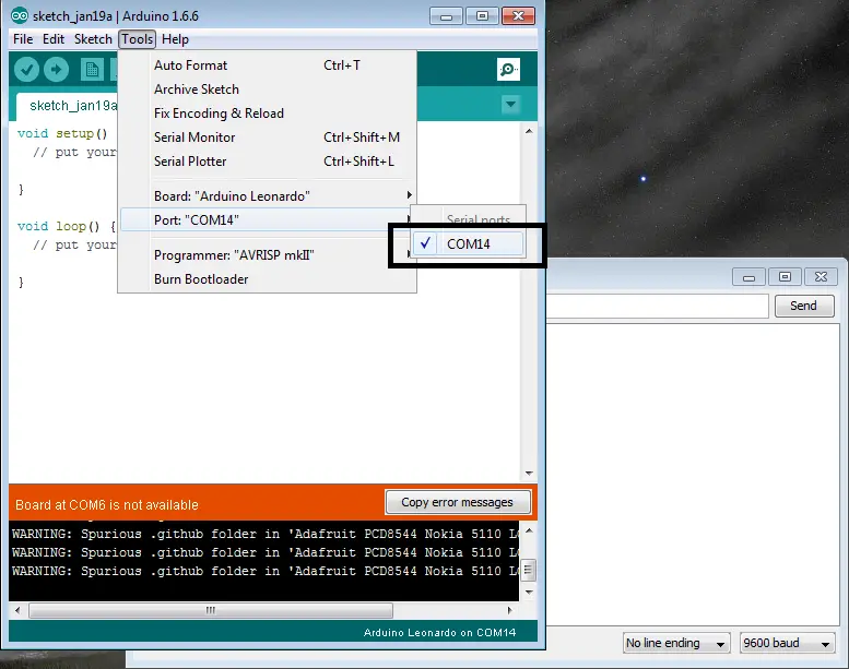
For those who are interested in building their own UI Serial Terminal Application, I’ve also taken this route when I was in the same situation. However, it may be unnecessarily overwhelming at this moment. You can just plan to do it in the future after getting this LAB done & tested with any terminal that works for you.
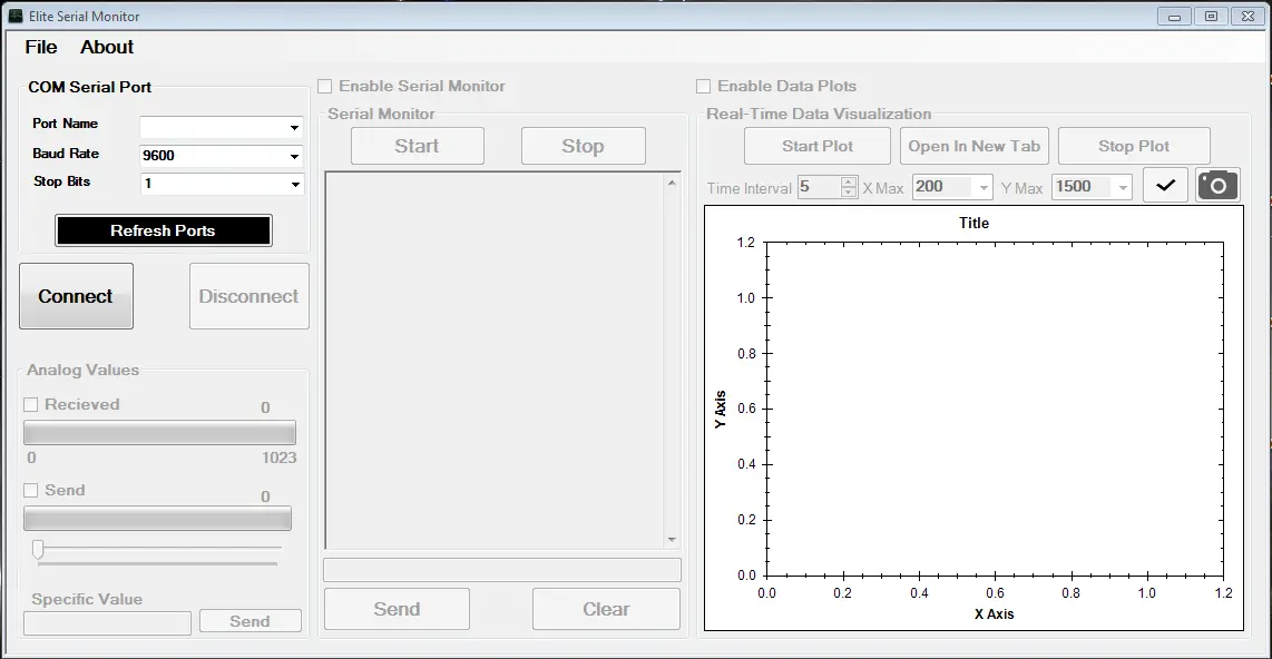
Here is the Serial Monitor (Download) that I’ve built back in the days (can’t remember how many years ago). I’ll be providing the source of it when it’s reworked as I’ll be working on a rework of it in the near future. It was written in C#, and you can build a similar one with python, java, etc.
Embedded Firmware
Assuming that you’ve already completed the UART tutorial, you should have successfully sent & received data via UART. The situation is much easier for this LAB, as we’ll be using the exact same UART receiver code to receive the data being sent from the PC. After checking the value of each received byte, we’ll be taking the corresponding action (e.g. Turn LED ON, OFF, Do whatever).
UART PC Interfacing – LAB
| Lab Name | PC Control With USB-TTL Converter |
| Lab Number | 19 |
| Lab Level | Beginner |
| Lab Objectives | Learn how to use the USB-TTL Converter module to convert serial data from the PC USB port to TTL UART which is compatible with almost all microcontrollers. Learn how to send/receive serial data to/from the PC from/to the microcontroller. |
1. Coding
Open the MPLAB IDE and create a new project name it “PC_Control_USB-TTL”. If you have some issues doing so, you can always refer to the previous tutorial using the link below.
Set the configuration bits to match the generic setting which we’ve stated earlier. And if you also find troubles creating this file, you can always refer to the previous tutorial using the link below.
Now, open the main.c file and let’s start developing the firmware for our project.
The first task is to initialize the UART module in order to operate in the receiver (slave) mode. Then, we have to save all the coming data to a buffer variable. The process of data reception and storage must be handled in the ISR as we’ve stated earlier.
In the main while loop, we can check if the received byte matches a specific value or not. To take some action (Switch an LED ON/OFF & Toggle Another LED). However, we’ll be doing this job inside the ISR as it’s not an excessive processing task, so it’s OK to have it done inside the ISR whenever a data frame is received.
The Full Code Listing For This LAB
|
1 2 3 4 5 6 7 8 9 10 11 12 13 14 15 16 17 18 19 20 21 22 23 24 25 26 27 28 29 30 31 32 33 34 35 36 37 38 39 40 41 42 43 44 45 46 47 48 49 50 51 52 53 54 55 56 57 58 59 60 61 62 63 64 65 66 67 68 69 70 71 72 73 74 75 76 77 78 |
/* * LAB Number: 19 * LAB Name: USB-TTL Converter Interfacing (PC -> MCU) * Author: Khaled Magdy * For More Information Visit My Website @ DeepBlueMbedded.com * */ #include <xc.h> #include <stdint.h> #include "config.h" #define _XTAL_FREQ 4000000 //--[ Control Data ]-- #define Blue_LED_ON 49 #define Blue_LED_OFF 50 #define Yellow_Toggle 51 //-------------------------------- // Functions Declarations void UART_RX_Init(void); // Globals uint8_t UART_Buffer = 0; //-------------------------------- // Main Routine void main(void) { //--[ Peripherals & IO Configurations ]-- UART_RX_Init(); // Initialize The UART in Master Mode @ 9600bps TRISB0 = 0; // Blue LED (Switch) TRISB1 = 0; // Yellow LED (Toggle) RB0 = 0; // Initially OFF RB1 = 0; // Initially OFF //--------------------------- while(1) { } return; } //-------------------------------- // Functions Definitions void UART_RX_Init() { BRGH = 1; // Set For High-Speed Baud Rate SPBRG = 25; // Set The Baud Rate To Be 9600 bps // Enable The Ascynchronous Serial Port SYNC = 0; SPEN = 1; // Set The RX-TX Pins to be in UART mode (not io) TRISC6 = 1; // As stated in the datasheet TRISC7 = 1; // As stated in the datasheet //--[ Enable UART Receiving Interrupts ]-- RCIE = 1; // UART Receving Interrupt Enable Bit PEIE = 1; // Peripherals Interrupt Enable Bit GIE = 1; // Global Interrupt Enable Bit //------------------ CREN = 1; // Enable Data Continous Reception } void interrupt ISR (void) { if (RCIF == 1) { UART_Buffer = RCREG; // Read The Received Data Buffer // This could have been done within the main loop. Since it's not // Excessive processing, so it's OK to do it here below if(UART_Buffer == Blue_LED_ON) RB0 = 1; // Blue LED ON if(UART_Buffer == Blue_LED_OFF) RB0 = 0; // Blue LED OFF if(UART_Buffer == Yellow_Toggle) RB1 = ~RB1; // Toggle Yellow LED RCIF = 0; // Clear The Interrupt Flag } } |
Note: The Data Bytes (49, 50, and 51) are the ASCII equivalents for the numeric characters (1, 2, and 3 respectively).
2. Simulation
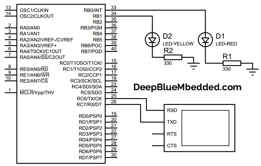
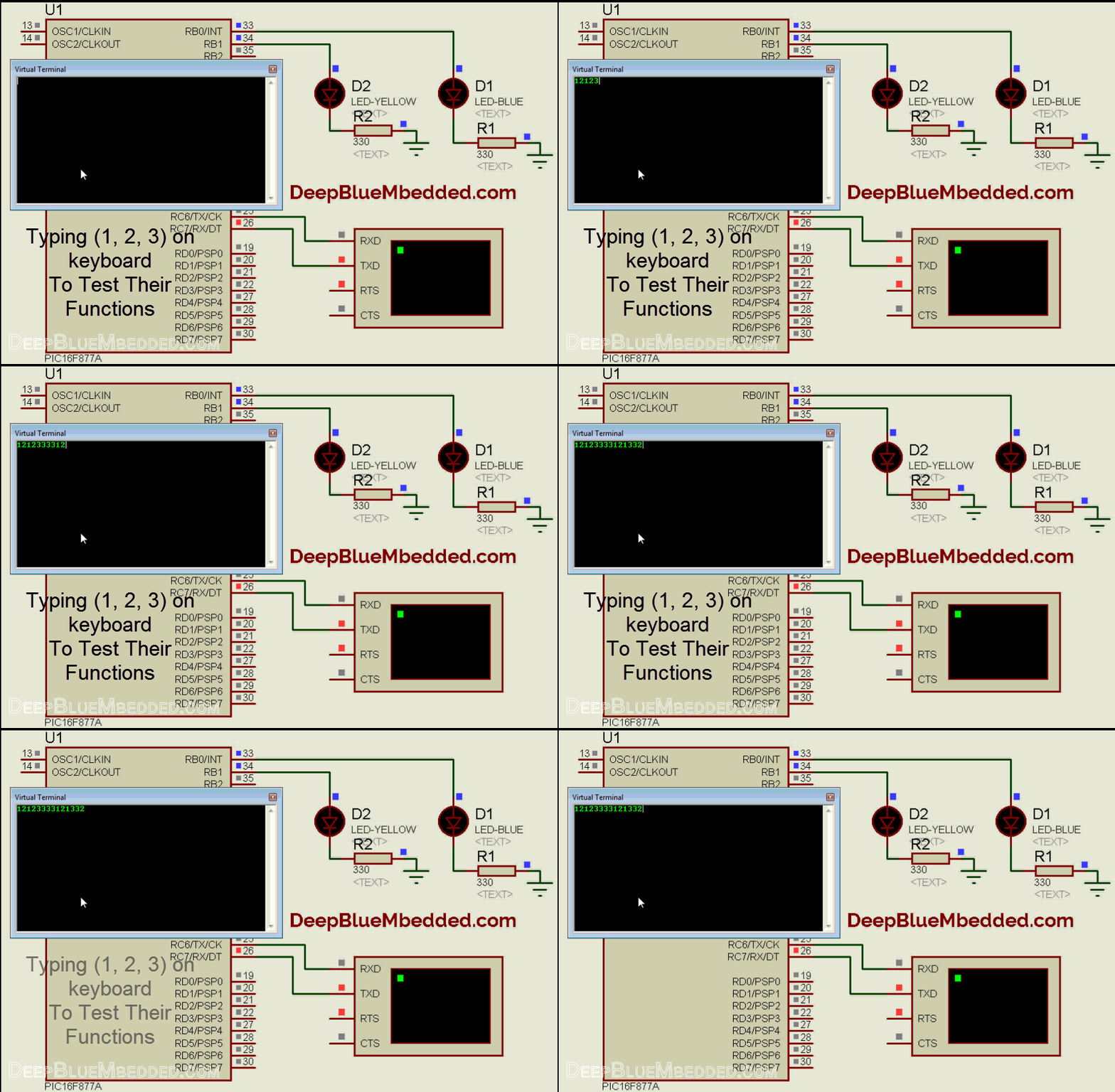
For simulation purposes, you can use the generic Virtual Terminal in Proteus and just type in the data which you wanna send to the microcontroller. It should give you an idea of what will be happening with the USB-TTL module in the real testing phase. And the connection diagram is just the same.
Here is an animation for the running simulation tests.
3. Prototyping
Wiring up this schematic on a breadboard should be an easy task. Just upload your firmware hex file to the microcontroller chip. And Open any serial terminal on your PC (the simplest way is to use the Arduino’s serial monitor). Make sure to set the baud rate to 9600 bps. You can also use my old custom-made serial monitor. And here is a video for the final output of this LAB.
 |
If you’ve any troubles or got stuck at any point, just drop me a comment. I’ll be always here and ready for help. Or even other readers may do a better job in this.
Concluding Remarks
1
The USB-TTL converter provides a very good yet easy to run solution for adding USB connectivity for your project. However, it’s inherently limited in many aspects as it’s not a full USB port and it can’t replace a real USB hardware in many applications. But if you need a moderately low-speed USB communication, then go for it. The additional complexity of building a new USB stack from scratch may not align with the limited time-budget of a simple project if it’s the case for you.
2
You can build your own serial monitor with whichever language you prefer (i.e Java, C++, Python, C#). Just search for a proper toolchain (toolkit) that supports building GUI applications (i.e QT for C++, .NET for C#, PyQT for python, etc).
| Previous Tutorial | Tutorial 20 | Next Tutorial | |||||


Are you sure that the VDD pin of the serial USB-TTL board has to be connected? I can’t understand it’s purpose.