| Previous Tutorial | Tutorial 3 | Next Tutorial | |||||
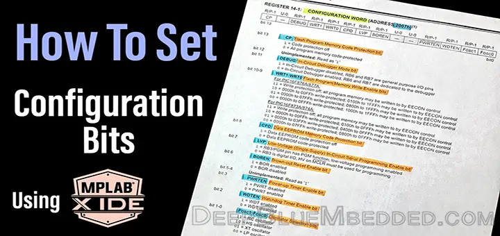
| Setting The Configuration Bits (Fuses) | |||||||
| PIC Microcontrollers Course Home Page ???? | |||||||
In this tutorial, we’ll discuss what are the configuration bits (fuse bits) and how to properly set their values for our Microchip PIC microcontroller using the MPLAB X IDE and XC8 compiler.
[toc]
What Are The Configuration Bits (Fuses)?
As in any design process, let’s say graphics design. There are some settings that are being tuned at the beginning of the design project such as dimensions, dpi, background, colors, etc. These settings are said to be “The configurations” of the project which will not be changed till the end ideally.
Similarly, in embedded software design, there are also some configurations for each MCU used in the whole project. Such as the type of oscillator internal/external, whether you’ll use a watchdog timer or not, whether there’ll be a reset pin or not, and so. These configurations are controlled via a dedicated specific register in the ROM, In our MCU it’s called “CONFIG_WORD”.
Every single bit in this register controls a specific feature, combined together in this register to control all the settings (configurations), Hence they are often called the “Configuration Bits”. Some books in the embedded literature call these bits as “Fuses”. All in all, these names stand for the same thing.
| Note | |||
|
The configuration register is typically resident in the ROM of a microcontroller. This means it’s part of the code itself which may not be changed while the application is running, But it’s only accessible/changeable during the programming (flashing) process. |
|||
The CONFIGURATION WORD Register
This 14-Bit register is located in the ROM (program) memory @ the address 2007h. You can easily find the description of this register in the datasheet at section 14.1 (page144).
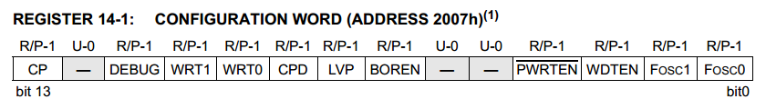
Writing 1 or 0 in each bit of this register will result in the activation/deactivation of a specific feature. Down below, I will show you what are the features being controlled by these bits. Let’s start at the LSB (0) all the way up to the MSB (13).
Fosc1 : Fosc2
Bit-0, Bit-1: The oscillator selection bits
The combination of these two bits determines which clock source will be used to feed the MCU clock input. There are basically 4 combinations of those couple of bits. Consequently, there are 4 options for the oscillator to select from.
| FOSC1 : FOSC0 | Oscillator Type |
| 1 1 | RC Oscillator |
| 1 0 | HS Oscillator |
| 0 1 | XT Oscillator |
| 0 0 | LP Oscillator |
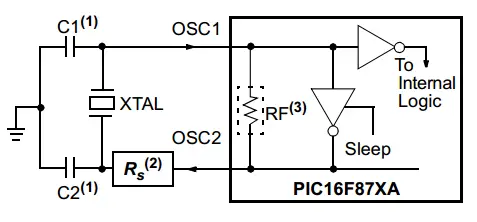
I- You can choose the first option RC oscillator by writing 1, 1 to bit-1, bit-0 respectively. Just in case you’re using an RC network to generate oscillating charging/discharging signal as a clock input for your MCU. Please, be advised that this method has a low accuracy for the oscillation frequency. I’m sure you’ll calculate the R & C values that will generate the desired frequency correctly. But resistors and capacitors always have a pretty high tolerance and their values aren’t exact.
II- You can choose to connect a crystal oscillator by writing 1, 0 to bit-1, bit-0 respectively. The HS stands for High-Speed. Which means it’s preferred to choose this option for crystals that are greater than or equal to >= 4MHz
III- You can choose to connect a crystal oscillator/ceramic resonator by writing 0, 1 to bit-1, bit-0 respectively. it’s preferred to choose this option for crystals that are less than or equal to <= 4MHz
IV- You can choose to connect a low-power crystal oscillator by writing 0, 0 to bit-1, bit-0 respectively. The LP stands for Low-Power. Which means it’s preferred to choose this option for crystals that below 400KHz
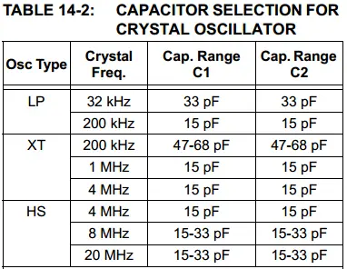
The table shown below indicates the frequency ranges and could be used as a guidance for capacitors selection. However, for these tutorials, we won’t add these capacitors at all. They are used for stabilization purposes. Higher capacitance increases the stability of oscillator but also increases the start-up time, so please be careful.
 |
 |
| Note | |||
|
In most cases, you will be using the HS or XT crystal oscillator option. It’s not as frustrating as it seems to be. |
|||
WDTEN
Bit-2: The WatchDog Timer Enable Bit
This bit is the most tricky one obviously. It controls the activation/deactivation of the watchdog timer module. If left ON, this will result in an undetectable insane series of time-out restarts. That will obviously block out your main code that will never complete its execution because of the infinite WDT time-out restarts.
If you’re willing to purposely use the WDT, you can turn this bit ON. Otherwise, you must clear it to be OFF. In the future, we’ll discuss the WDT in detail. So up till then, let this bit OFF.
PWRTEN
Bit-3: The Power-Up Timer Enable Bit
This bit controls the activation/deactivation of the Power-Up Timer. The Power-up Timer provides a fixed 72 ms nominal time-out on power-up. This hardware module operates on an internal RC oscillator built-in the chip itself.
The PWRT‘s time delay allows VDD to rise to an acceptable level before the MCU starts executing the program. The PWRTEN configuration bit allows for enabling or disabling the Power-Up Timer. In the very basic applications, the effect of the PWRT will not be noticeable.
—-
Bit-4, Bit-5: Unimplemented
BOREN
Bit-6: Brown-Out Reset Enable Bit
This bit enables/disables the Brown-Out Reset circuit. If VDD falls below VBOR (about 4V) for a time period longer than TBOR (about 100 µS), the brown-out situation will reset the whole MCU device. If VDD falls below VBOR for less
than TBOR, a Reset may not occur.
Once the brown-out occurs, the device will remain in Brown-out Reset until VDD rises above VBOR. The Power-up Timer then keeps the device in Reset for TPWRT (about 72 mS).
The Power-up Timer is always enabled when the Brown-out Reset circuit is enabled, regardless of the state of the PWRTEN configuration bit.
LVP
Bit-7: Low-Voltage (Single-Supply) In-Circuit Serial Programming Enable bit
This bit switches between low/high voltage programming modes. if it’s cleared (turned OFF), RB3 is a digital I/O and the HV on MCLR pin. This must be used for programming the MCU chip. If this bit is set (turned ON), RB3/PGM pin has the PGM function, And the low-voltage programming mode is enabled. The HV refers to the programming voltage (about 13v) required to flash the hex code files to the MCU’s memory.
For these tutorials, we’ll be using the High-Voltage programming mode with the hardware PICkit2, 3. So we’ll leave this bit as default OFF.
CPD
Bit-8: Data EEPROM Memory Code Protection bit
This bit enables/disables the protection of the EEPROM memory data. Typically a hardware programmer kit (e.g. PICkit2, PICkit3) is capable of reading out all the content of the EEPROM memory of a microcontroller. If you’re creating a product with a PIC MCU, you should think of keeping its memory contents out of the users’ reach.
For these tutorials, we’ll leave this bit OFF as default. But you may consider using it in the future.
WRT
Bit-9, Bit-10: Flash Program Memory Write Enable bits
The combination of these two bits selects a page from the flash program memory to protect. Or if left as default all the pages will not be protected. We’ll also leave these bits OFF.
DEBUG
Bit-11: In-Circuit Debugger Mode Bit
This bit enables/disables the In-Circuit Debugger Mode. If you’re using a hardware debugging tool (e.g. PICkit3), you may need to set this feature ON. Otherwise, leave it OFF. For our tutorials, we’ll leave this feature OFF as default.
—-
Bit-12: Unimplemented
CP
Bit-13: Flash Program Memory Code Protection Bit
This bit enables/disables the Flash Program Memory Code Protection. As we’ve stated above, that a hardware programmer kit (e.g. PICkit2) can easily read-out the EEPROM memory contents of an MCU Chip. It’s also capable of reading (extracting) the code from the flash memory as a hex file.
If you’re creating an embedded solution with a Microchip PIC MCU, you must consider blocking-out your firmware code. Nobody will tolerate seeing a high-copy of his own product being sold for a lower price! You shouldn’t wait until it happens while you can prevent this from happening in the first place!
However, these tutorials are designed for educational purposes mainly, so we’ll leave this feature OFF as default. But as I said, for commercial applications this will be substantial.
How To Set The Config. Bits Within MPLAB
There is a GUI (graphical user interface) tool provided by Microchip’s MPLAB IDE. This is called Configuration Bits Code Generator. This tool generates the required C-Code for you to set the configuration bit as desired.
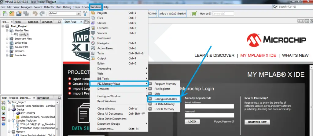
In the top menu bar click window > PIC Memory Views > Configuration Bits as shown down below
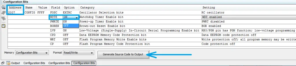
A small window will show up at the bottom of the IDE screen, in which you’ll find the name of the register CONFIG WORD with its specific address 2007h. Each feature is easily turned ON/OFF or configured as you wish with a few clicks. After setting everything up as you need, click the “Generate Source Code” button. As you can see down below
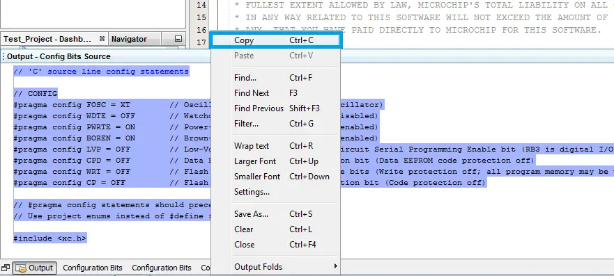
After generating the source code for the configuration bits. You can copy/past it either at the main.c file or in a dedicated file for the configuration which I personally do recommend.
Paste the code in your header config.h file and don’t forget to include this file in your main.c code file for your project.
The Generic Configurations For PIC16F877A
Here is the generic configuration bits source code. Which you can easily copy/paste in your config.h header file for these tutorials. If there is a specific modification, it’ll be mentioned in the respective tutorial. Otherwise, it’s highly recommended to use the code down below.
|
1 2 3 4 5 6 7 8 9 10 11 12 13 14 15 16 17 |
// [ PIC16F877A ] Configuration Bit Settings // #pragma config statements should precede project file includes. // Use project enums instead of #define for ON and OFF. // CONFIG #pragma config FOSC = XT // Oscillator Selection bits (XT oscillator) #pragma config WDTE = OFF // Watchdog Timer Enable bit (WDT disabled) #pragma config PWRTE = ON // Power-up Timer Enable bit (PWRT enabled) #pragma config BOREN = ON // Brown-out Reset Enable bit (BOR enabled) #pragma config LVP = OFF // Low-Voltage (Single-Supply) In-Circuit Serial Programming Enable bit // (RB3 is digital I/O, HV on MCLR must be used for programming) #pragma config CPD = OFF // Data EEPROM Memory Code Protection bit (Data EEPROM code protection off) #pragma config WRT = OFF // Flash Program Memory Write Enable bits // (Write protection off; all program memory may be written to by EECON control) #pragma config CP = OFF // Flash Program Memory Code Protection bit (Code protection off) #include <xc.h> |
| PIC Microcontrollers Course Home Page ???? |
|||||||
| Previous Tutorial | Tutorial 3 | Next Tutorial | |||||
Top ????
IDE give me error –> #include “config.h”
Unresolved include file.