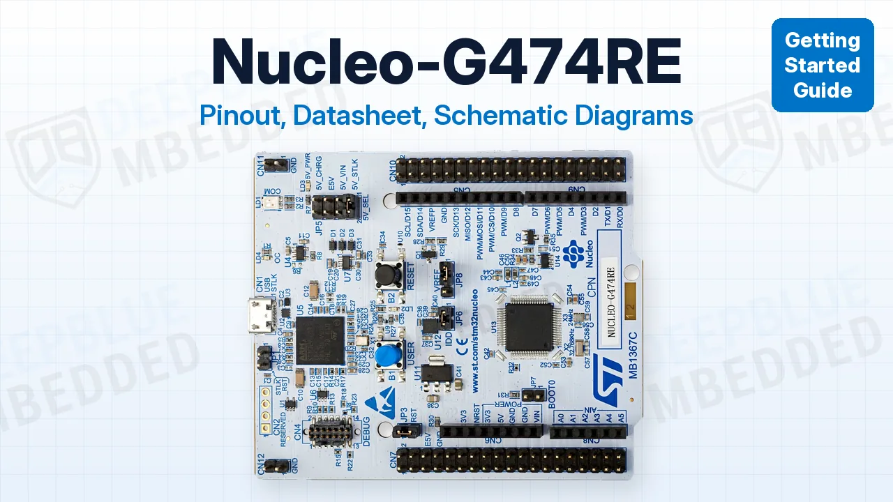
In this guide, you’ll find the Nucleo-G474RE pinout diagram, its datasheet and schematic diagram, and every pin group explained with its default pins and gotchas. Without further ado, let’s get right into it!
The Nucleo-G474RE is ST’s official Nucleo-64 board for the STM32G474RE, a 170MHz Arm Cortex-M4 with FPU, 512KB Flash and 128KB RAM, built for digital power and motor control. It packs a 184ps HRTIM, 3 advanced timers, 5 ADCs, 6 op-amps, 7 comparators, and 3 FDCAN ports, with an on-board STLINK-V3E debugger, so all you need is a USB cable.
Nucleo-G474RE Pinout Diagram
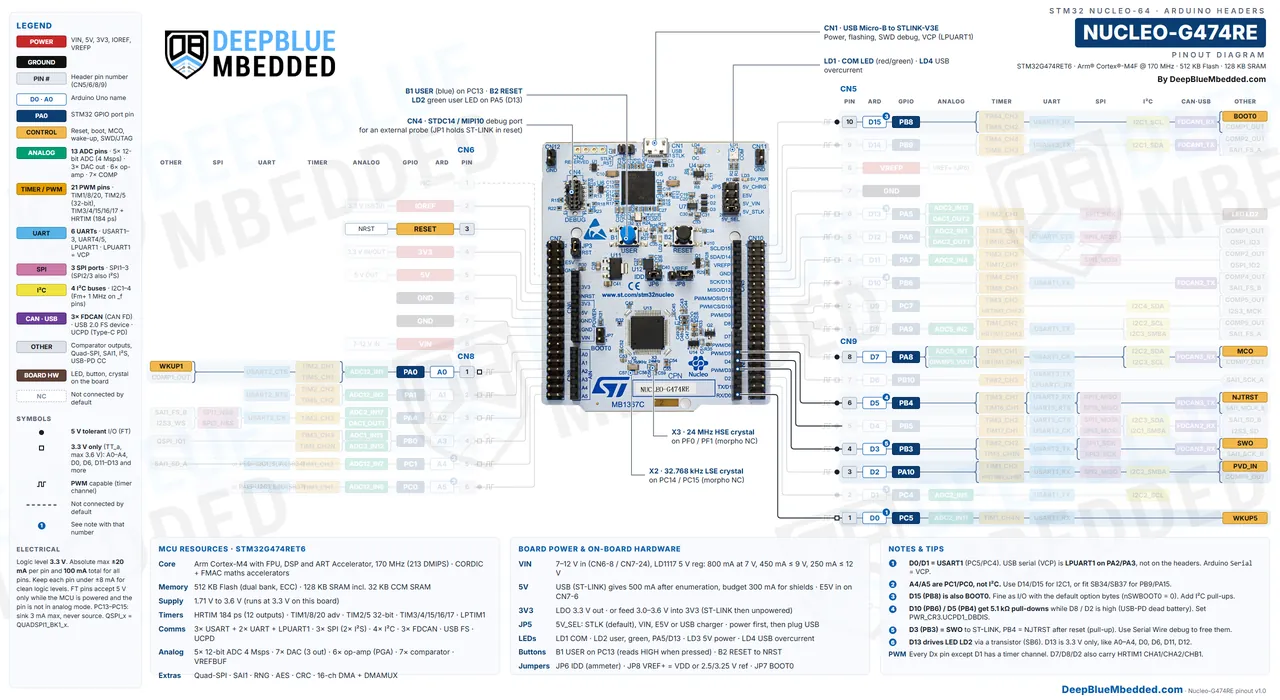
Here is a detailed Nucleo-G474RE Pinout Diagram with colored labels and legends to help you easily identify the functionalities that each pin can perform. This first diagram covers the Arduino Uno V3 headers (CN5, CN6, CN8, and CN9), which is where most shields and jumper wires go.
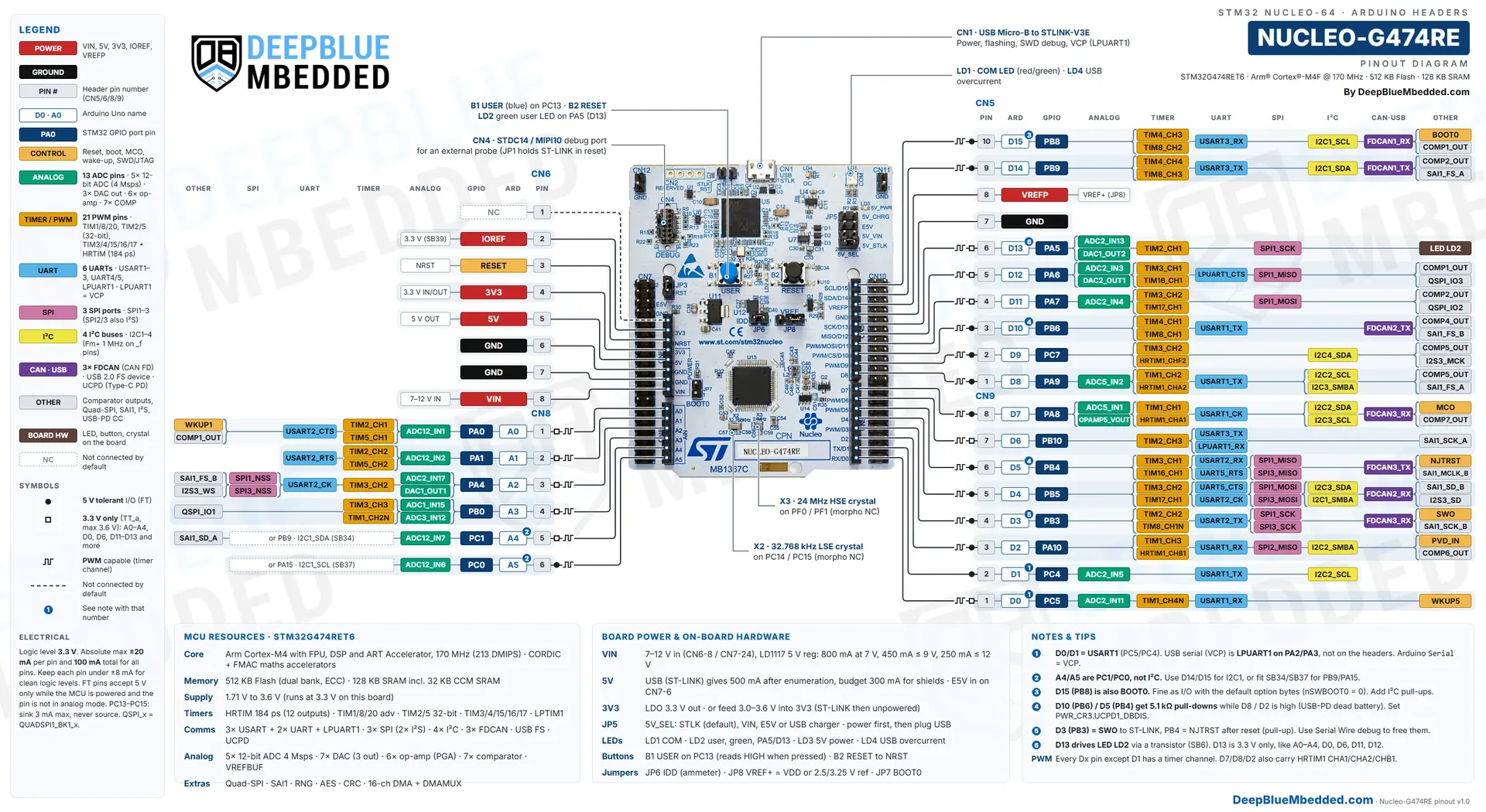
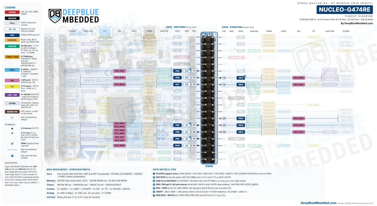
Each row shows the header pin number, the Arduino name (D0–D15, A0–A5), the STM32 GPIO name and its alternate functions, color-coded by peripheral. The small dot marks a 5v-tolerant pin, the square marks a 3.3v-only pin (there are many on this board), and the numbered badges point to the notes at the bottom of the diagram.
Nucleo-G474RE Morpho CN7 Pinout
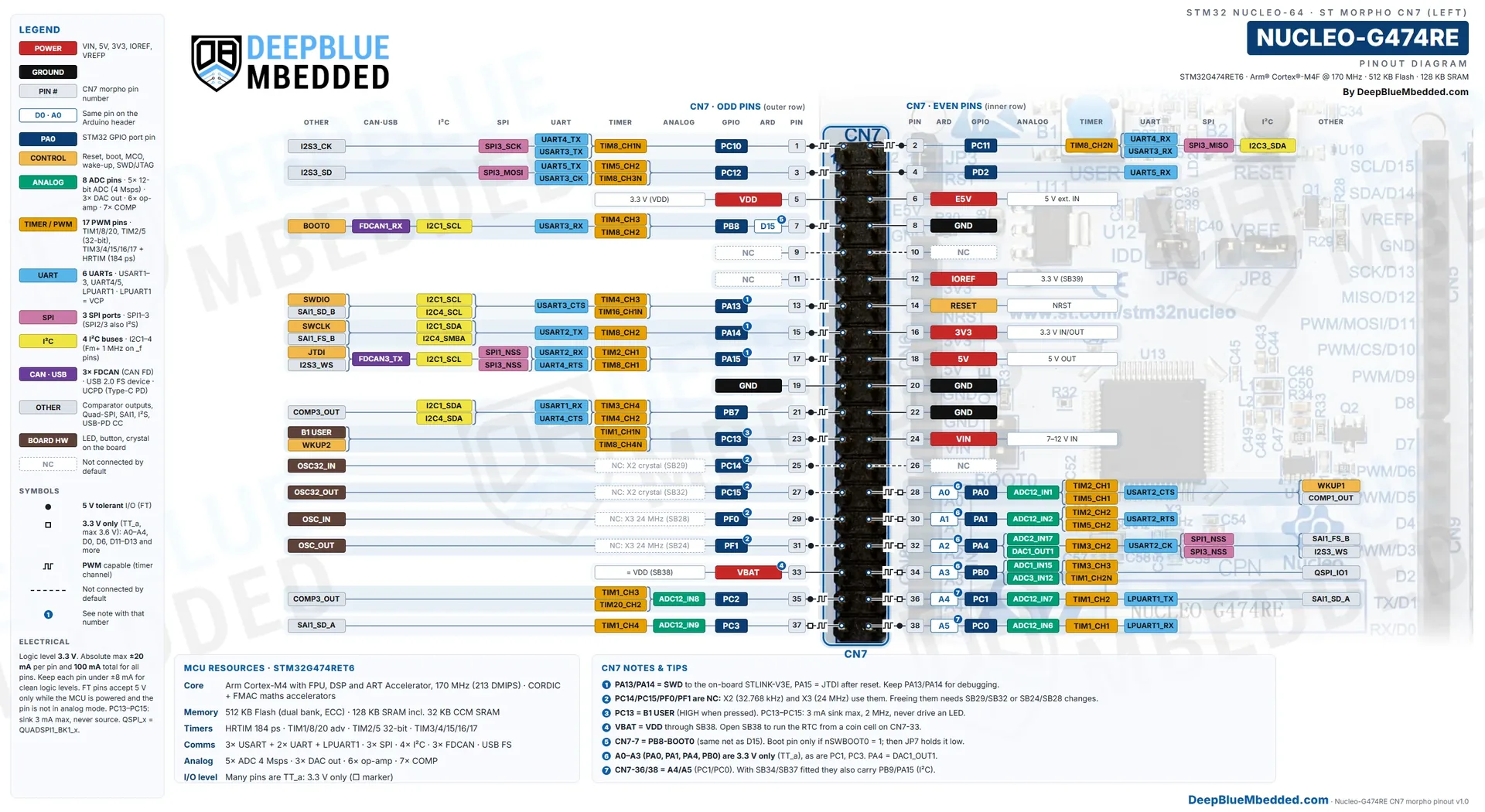
The left ST Morpho header CN7 is a 2×19 male header. Odd pins (1, 3, 5…37) are on the outer column and even pins are on the inner column, with pin 1 at the top, next to the STLINK-V3E part of the board.
Nucleo-G474RE Morpho CN10 Pinout
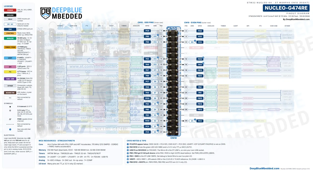
The right ST Morpho header CN10 is also 2×19, but here the odd pins are on the inner column. It carries most of the G474’s power-control signals: 10 of the 12 HRTIM outputs, the USB pins, two FDCAN pin pairs, and the op-amp and comparator pins on PB11–PB15.
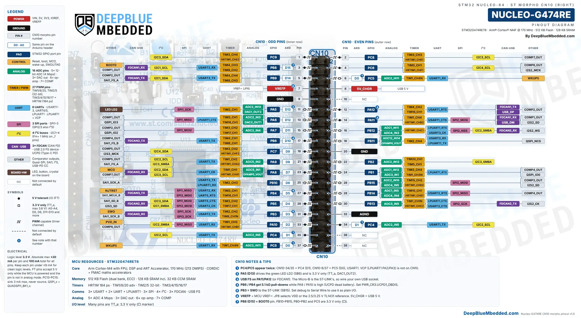
Every Arduino header signal is also on the Morpho headers (for example, D13/PA5 is also CN10-11), so the Morpho headers are a superset. D0 (PC5) and D1 (PC4) even appear twice on CN10 (CN10-6/37 and CN10-34/35). The only GPIOs you won’t find on any header are PA2/PA3, which go to the STLINK-V3E Virtual COM port.
Buy a Nucleo-G474RE: If you don’t have one yet, you can get the official ST board from Amazon or AliExpress. It comes with the STLINK-V3E debugger on board, so you can start programming it right away.
Download Nucleo-G474RE Pinout Diagrams (Full Resolution)
All 3 Nucleo-G474RE pinout diagrams (Arduino headers, CN7 and CN10 morpho) in full resolution (5120×2800 px WebP), in one ZIP file. Print them, zoom in, or keep them next to your bench. Please consider supporting my work if it helped you.
Nucleo-G474RE Datasheet
This development board is built around the STM32G474RET6 microcontroller (LQFP64 package). Here are the official Nucleo-G474RE datasheet and documents you’ll need for it, all linked to ST’s own servers so you always get the latest revision:
| Document | ID | Revision | What you’ll use it for | Link |
|---|---|---|---|---|
| STM32G474xB/xC/xE datasheet | DS12288 | Rev 6 (Nov 2021) | Pin definitions (FT/TT), alternate-function table, electrical limits | |
| STM32G4 series reference manual | RM0440 | Rev 9 (Mar 2025) | Registers and how every peripheral works (HRTIM, ADC, FDCAN…) | |
| STM32G4 Nucleo-64 boards (MB1367) user manual | UM2505 | Rev 7 (May 2026) | Board pinout tables, jumpers, solder bridges, power options | |
| NUCLEO-G474RE data brief | DB2196 | Rev 23 (Oct 2026) | One-page board summary and order code | |
| STM32G474xx device errata | ES0430 | Rev 10 (Nov 2026) | Known silicon limitations and workarounds | |
| MB1367 G474RE board schematic | MB1367 D-01 | Sep 2025 | Full board circuit (see the next section) |
Which document do I need? The datasheet for pin functions and electrical limits, the reference manual for registers, and the UM2505 user manual for jumpers, solder bridges, and the header map. Note that this board uses UM2505, not the UM1724 manual of the older Nucleo-64 boards like the Nucleo-F446RE. All of them are listed on the official NUCLEO-G474RE product page.
Nucleo-G474RE Schematic
The Nucleo-G474RE schematic is ST’s MB1367 rev D-01 drawing, which is the G474RE version of the STM32G4 Nucleo-64 board (the same PCB is used by the NUCLEO-G431RB and NUCLEO-G491RE). Here are its 6 circuit sheets; click a page to view it full screen.
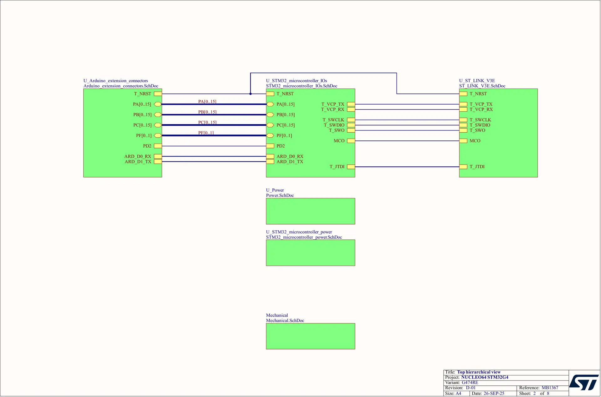
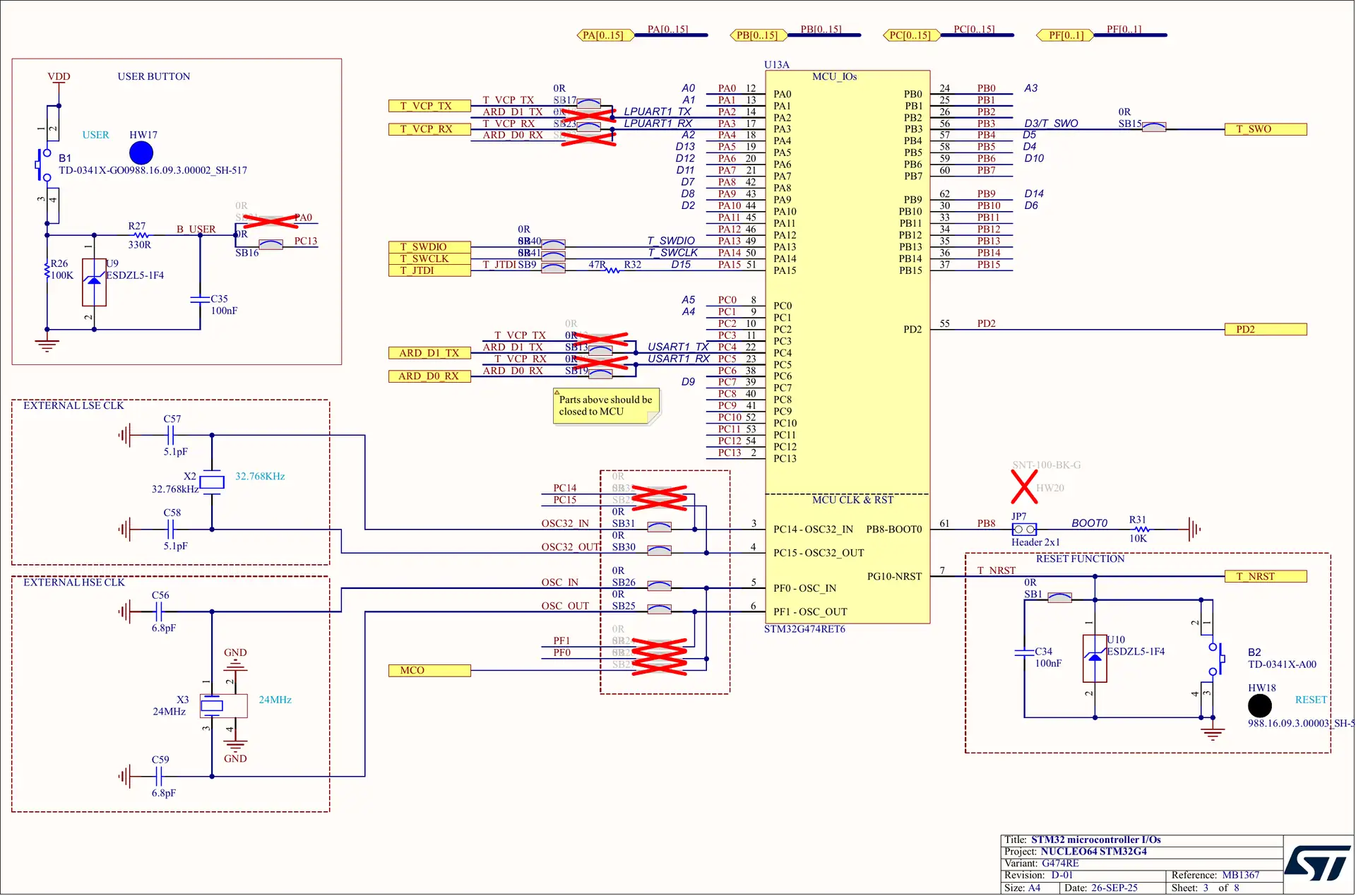
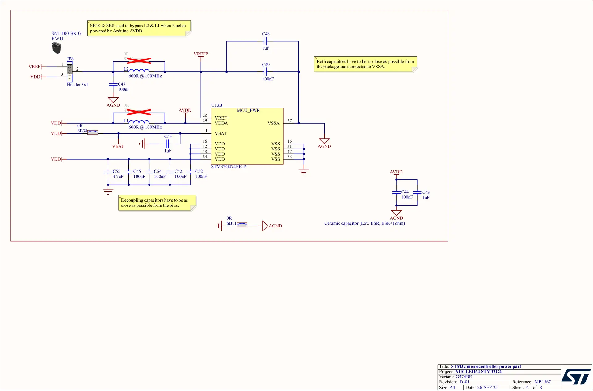
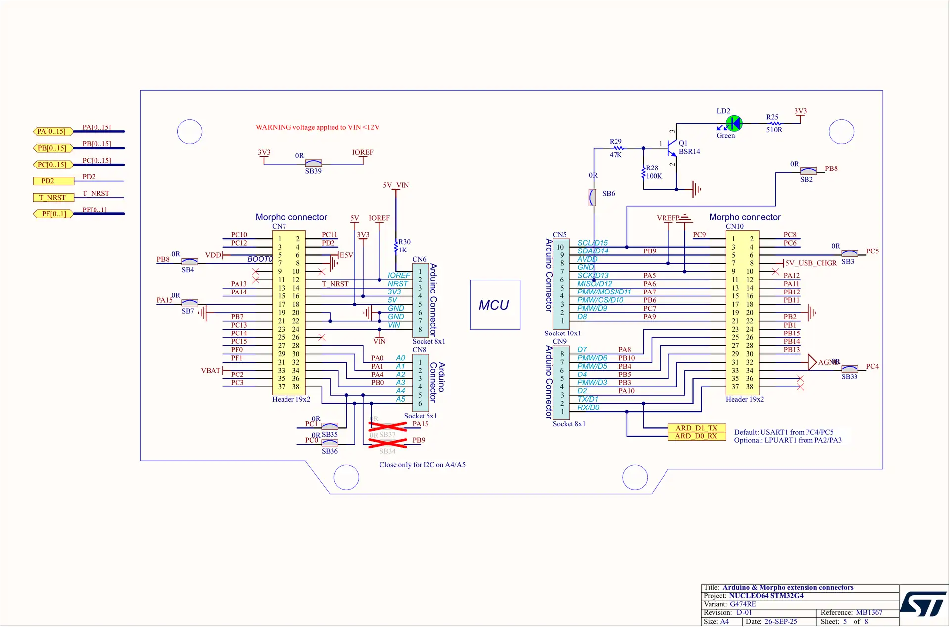
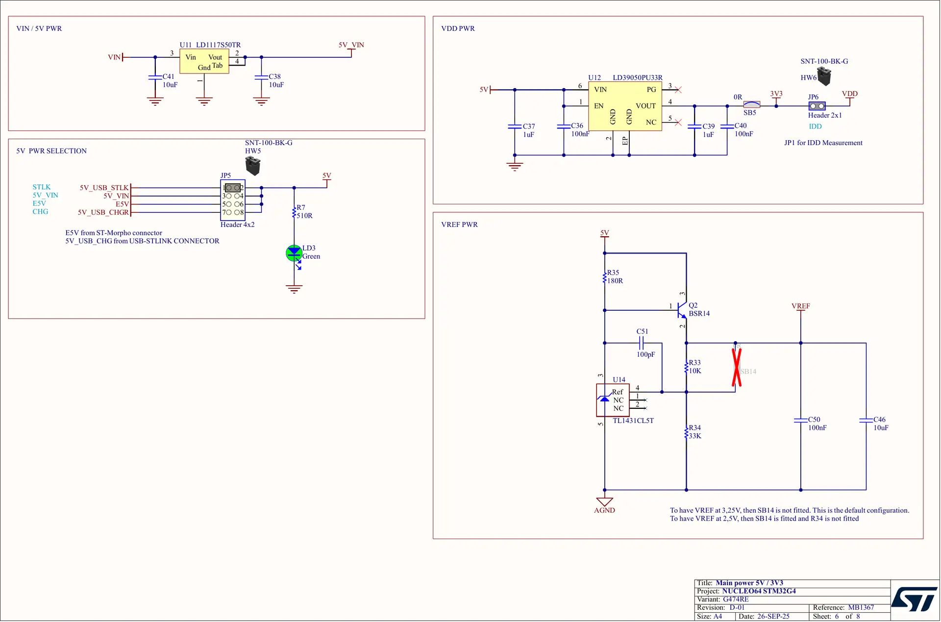
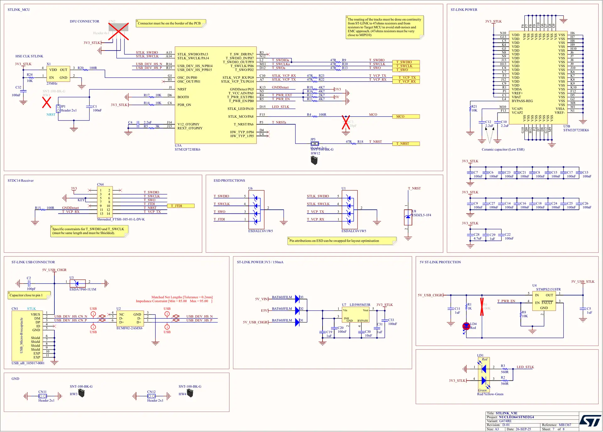
Official source: MB1367 G474RE D-01 schematic (PDF) from the NUCLEO-G474RE product page (CAD Resources). Here’s what to look at on each sheet:
- Main power (sheet 5): the STLINK-V3E USB 5v goes through a current-limited power switch (LD4 lights above 500mA). VIN (7v–12v) feeds the LD1117S50 5v regulator, and jumper JP5 picks the 5v source (STLINK, VIN, E5V or a USB charger). The 5v rail feeds the LD39050PU33R 3.3v regulator (U12, 500mA) that powers the MCU.
- MCU I/Os (sheet 2): the solder bridges that route the pins: SB17/SB23 put LPUART1 (PA2/PA3) on the Virtual COM port, SB13/SB19 put USART1 (PC4/PC5) on D1/D0, SB35/SB36 put PC1/PC0 on A4/A5, SB2/SB4 bring PB8 to D15 and CN7-7, and SB6 connects LD2 to PA5. The user button B1 is wired to VDD, so PC13 reads HIGH when pressed.
- Clocks (sheet 2): unlike the older Nucleo-64 boards, the G474RE has a real 24MHz HSE crystal (X3) on PF0/PF1 and a 32.768kHz LSE crystal (X2) on PC14/PC15. The STLINK-V3E MCO can feed the HSE instead (SB27, open by default).
- MCU power (sheet 3): VDDA goes through ferrite bead L1, and VREF+ through L2 to jumper JP8, which picks a TL1431 reference (3.25v, or 2.5v with SB14) or VDD. VBAT is tied to VDD by SB38.
- STLINK-V3E (sheet 6): an STM32F723 handles SWD debugging (PA13/PA14, PB3 SWO, NRST), drag-and-drop flashing and the Virtual COM port, through the USB Micro-B connector CN1. CN4 (STDC14/MIPI10) takes an external probe, and JP1 holds the STLINK-V3E in reset.
- Extension connectors (sheet 4): the Arduino (CN5/CN6/CN8/CN9) and Morpho (CN7/CN10) headers, with each solder-bridge option drawn next to the pin it changes.
Nucleo-G474RE Specs
The Nucleo-G474RE combines a 170MHz STM32G474RET6 with ST’s STM32G4 Nucleo-64 board (MB1367). Here are its specifications, including the board-level parts that chip-only spec lists usually skip.
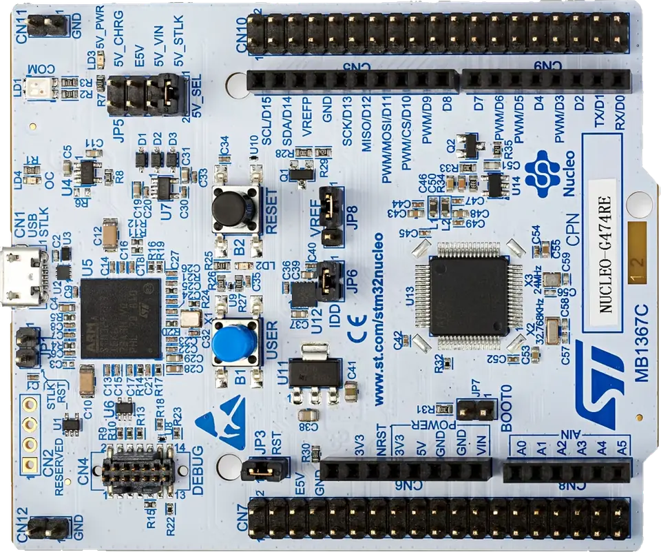
Get a Nucleo-G474RE: The official ST board is the one I recommend. Grab it from Amazon or AliExpress.
| Item | Nucleo-G474RE |
|---|---|
| MCU | STM32G474RET6, LQFP64 |
| Core | Arm Cortex-M4 with FPU and DSP, up to 170MHz (213 DMIPS), ART Accelerator, CORDIC and FMAC math accelerators |
| Memory | 512KB Flash (dual bank, ECC), 128KB SRAM (including 32KB CCM SRAM) |
| Logic level | 3.3v; 18 of the header GPIOs are 3.3v-only (TT), the rest are 5v tolerant (FT) |
| GPIO pins | 49 on the Morpho headers (45 connected by default), 22 on the Arduino headers |
| Board supply | USB 5v (500mA), VIN 7v–12v, E5V 4.75v–5.25v, a USB charger, or 3.3v direct |
| 5v regulator | LD1117S50: 800mA at 7v in, 450mA at 7v–9v, 250mA at 9v–12v |
| 3.3v regulator | LD39050PU33R, 500mA |
| Clocks | 24MHz HSE crystal (X3), 32.768kHz LSE crystal (X2) |
| Debugger | On-board STLINK-V3E: SWD, drag-and-drop flashing, Virtual COM port on LPUART1 |
| USB connector | Micro-B (CN1), for the STLINK-V3E only |
| Headers | Arduino Uno V3 (CN5, CN6, CN8, CN9) + two 2×19 ST Morpho headers (CN7, CN10), STDC14/MIPI10 debug connector (CN4) |
| User I/O | LD2 green LED (PA5), B1 user button (PC13, active HIGH), B2 reset button |
| PCB | MB1367 (STM32G4 Nucleo-64), shared with the NUCLEO-G431RB and NUCLEO-G491RE |
Nucleo-G474RE Specifications Summary
- The Nucleo-G474RE runs the STM32G474RET6 at up to 170MHz with 512KB Flash and 128KB RAM.
- It has a high-resolution timer (HRTIM) with 184ps resolution and 12 outputs, all 12 of them on the headers.
- It has 5x 12-bit ADCs (4Msps), 3 external DAC outputs, 6 op-amps and 7 comparators.
- 18 header GPIOs are 3.3v only, including A0–A4, D0, D6, D11, D12, and D13. The rest are 5v tolerant.
- The Virtual COM port is LPUART1 on PA2/PA3, and D0/D1 are USART1 (PC5/PC4).
- 21 Arduino pins can output PWM: every D pin except D1, plus A0–A5.
- The default I2C pins are D15 (PB8, SCL) and D14 (PB9, SDA); A4/A5 are not I2C by default.
- The default SPI pins are D13 (SCK), D12 (MISO), D11 (MOSI) on SPI1.
- It has 3x FDCAN (CAN FD) controllers; FDCAN1 is on D15/D14. A transceiver is needed.
- D15 (PB8) is also the BOOT0 pin.
- The user LED LD2 is on PA5 (D13), and the user button B1 on PC13 reads HIGH when pressed.
- VIN accepts 7v–12v, and the 3.3v regulator gives up to 500mA.
Nucleo-G474RE Peripherals: MCU vs On the Headers
The STM32G474RE has more peripherals than the Arduino headers can show. This table tells you what the chip has and where you can actually reach it on the board.
| Peripheral | STM32G474RE (LQFP64) | On the Arduino headers | On the Morpho headers |
|---|---|---|---|
| ADC | 5x 12-bit, 4Msps, 26 external channels | 13 pins (A0–A5, D0, D1, D7, D8, D11–D13) | 22 pins (PA2/PA3 go to the VCP, PF0/PF1 to the crystal) |
| DAC | 7 channels (3 external outputs + 4 internal) | A2 (DAC1_OUT1), D13 (DAC1_OUT2), D12 (DAC2_OUT1) | same 3 |
| Op-amps / comparators | 6 op-amps (PGA), 7 comparators | some inputs and outputs | all pins |
| HRTIM | 6 timer units, 12 outputs, 184ps | CHA1 (D7), CHA2 (D8), CHB1 (D2), CHF2 (D9) | all 12 outputs |
| Other timers | TIM1/8/20 (advanced), TIM2/5 (32-bit), TIM3/4/15/16/17, TIM6/7, LPTIM1 | 21 PWM pins | 17 on CN7, 27 on CN10 |
| U(S)ART | USART1/2/3, UART4/5, LPUART1 | USART1 (D0/D1 default, D2/D8, D10), USART3, LPUART1 | all six; LPUART1 PA2/PA3 is the VCP |
| SPI / I²S | SPI1, SPI2, SPI3 (SPI2/3 also I²S) | SPI1 (D11–D13), SPI3 (D3–D5) | SPI1–SPI3 |
| I²C | I2C1–I2C4 (Fm+ on _f pins) | I2C1 (D14/D15), I2C2, I2C3, I2C4_SDA | all four |
| FDCAN | 3x CAN FD | FDCAN1 (D14/D15), FDCAN2 (D4/D10), FDCAN3 (D7, D3/D5) | plus PA11/PA12, PB12/PB13, PA15 |
| USB | USB 2.0 FS device + UCPD (Type-C PD) | UCPD CC1/CC2 on D10/D5 | USB on PA11/PA12 (no USB socket for the MCU) |
| Others | Quad-SPI, SAI1, RNG, AES, CRC, CORDIC, FMAC, VREFBUF | some signals | yes |
There’s no FSMC and no SPI4 on this 64-pin package; those exist only on the larger STM32G474 packages.
Nucleo-G474RE Quick Pin Selection Guide
Not sure which pin to use? Here are the Nucleo-G474RE pins I’d pick first for each job, and why.
| Use case | Recommended pins | Why |
|---|---|---|
| Serial to the PC | LPUART1 (PA2/PA3) via USB | Already wired to the STLINK-V3E Virtual COM port; Serial in Arduino |
| Serial to a module (GPS, Bluetooth…) | USART1: D1 (TX), D0 (RX) | The Arduino UART pins, free and on USART1 by default |
| I2C sensors and displays | D15 (SCL), D14 (SDA) | The default Wire pins; add pull-ups |
| SPI devices | D13 (SCK), D12 (MISO), D11 (MOSI), D10 (CS) | The default SPI pins (SPI1) |
| Power converter PWM | HRTIM: D7/D8 (CHA1/CHA2), D2 (CHB1), PB12–PB15 (CHC/CHD) | 184ps resolution, dead-time, fault inputs |
| Motor control (3-phase) | TIM1: D7, D8, D2 + PB13, PB14, PB15 (CH1N–CH3N) | Complementary outputs with dead-time and break input |
| Analog inputs | A0, A1, A3, A5 + D7, D8 | Free ADC pins with no board load |
| Analog output (DAC) | A2 (PA4) | DAC1_OUT1 with no LED load (D13 drives LD2) |
| CAN FD bus | D15 (FDCAN1_RX), D14 (FDCAN1_TX) | With a CAN FD transceiver |
| USB device | PA11 (DM), PA12 (DP) on CN10 | USB FS with the on-chip PHY |
| On-board LED / button | PA5 (LD2), PC13 (B1) | LED_BUILTIN and USER_BTN in Arduino |
| 5v signals | Any FT pin: D1–D5, D7–D10, D14, D15, A5 | The 5v-tolerant header pins |
| Safest general GPIO | D4, D7, D9, and the Morpho-only PC6, PC8–PC12, PD2 | No board load, no debug, boot or UCPD role |
Nucleo-G474RE Pins to Use With Caution
| Pin | Reason | What to do |
|---|---|---|
| A0–A4, D0, D6, D11–D13 (and PB1, PB2, PB11–PB15, PC3) | TT pins: not 5v tolerant (max 3.6v) | Never connect 5v signals; use a level shifter or a divider |
| PA5 (D13) | Drives LED LD2 through a transistor (SB6) | Fine for SPI and PWM; open SB6 for a clean DAC output |
| PA2, PA3 | LPUART1 to the STLINK-V3E Virtual COM port, not on any header | Use them for printf; use USART1 (D0/D1) for modules |
| PB8 (D15, CN7-7) | BOOT0 pin | Check the nSWBOOT0 option bit before using it as I/O at reset (see Boot Pins) |
| PB4 (D5), PB6 (D10) | UCPD dead-battery pull-downs (5.1kΩ) when PA9/PA10 are HIGH | Disable them with HAL_PWREx_DisableUCPDDeadBattery() |
| PA13, PA14 | SWD pins of the STLINK-V3E | Don’t reuse them, or you lose debugging |
| PB3 (D3), PB4 (D5), PA15 | JTAG pins (SWO, NJTRST, JTDI) after reset | Set debug to Serial Wire to free them; PB4 has a pull-up after reset |
| PC13, PC14, PC15 | Backup-domain pins: 3mA sink max, 2MHz max, never a current source | Use PC13 for B1 only; PC14/PC15 are taken by X2 |
| PF0, PF1 | Taken by the 24MHz crystal X3 | Not on CN7 unless you move SB24/SB28 and SB25/SB26 |
| PC1, PC0 (A4, A5) | Not I2C by default | Use D15/D14 for I2C, or fit SB34/SB37 |
Nucleo-G474RE Pins Functions
The 49 GPIO pins on the Nucleo-G474RE headers are divided into the following groups based on the hardware functionality they’re used for. Most pins have several alternate functions, so one pin can belong to more than one group.
- Power Pins: VIN, 5V, 3V3, IOREF, E5V, 5V_CHGR, VREFP, VBAT, GND
- 49x Digital GPIO Pins (22 on the Arduino headers)
- 16x External Interrupt Lines (any GPIO)
- 22x ADC Analog Input Pins (13 on the Arduino headers)
- 3x DAC Output Pins
- 6x Op-Amps & 7x Comparators
- 43x PWM Pins (21 on the Arduino headers)
- 12x HRTIM Outputs and advanced-timer pins
- 6x UART Ports
- 4x I2C Buses
- 3x SPI Ports
- 3x FDCAN Ports
- USB & USB-C PD (UCPD) Pins
- Debug (SWD) & Boot Pins
We’ll discuss each pin group in the following sections one by one in more detail.
Nucleo-G474RE Power Pins
The Nucleo-G474RE can be powered from the USB connector (5v, 500mA), the VIN pin (7v–12v), the E5V pin (4.75v–5.25v), a USB charger, or directly from 3.3v. Jumper JP5 selects the 5v source. The power pins are highlighted in red in the pinout diagrams.
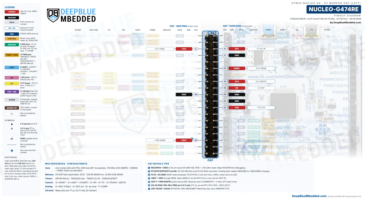
| Pin | Header Pins | Range | Notes |
|---|---|---|---|
| VIN | CN6-8, CN7-24 | 7v–12v in | LD1117 5v regulator: 800mA at 7v, 450mA at 7v–9v, 250mA at 9v–12v. Set JP5 to 5V_VIN |
| E5V | CN7-6 | 4.75v–5.25v in | 500mA max. Set JP5 to E5V |
| 5V_CHGR | CN10-8 | 5v | USB charger on CN1, no debugging. Set JP5 to 5V_CHGR |
| 5V | CN6-5, CN7-18 | 5v out | Limited by the source you power the board from |
| 3V3 | CN6-4, CN7-16 | 3.3v out / 3.0v–3.6v in | 500mA regulator out; as an input up to 1.3A, but the STLINK-V3E is then unpowered |
| IOREF | CN6-2, CN7-12 | 3.3v | Tells shields the I/O level (SB39) |
| VREFP | CN5-8, CN10-7 | 3.25v / 2.5v / VDD | MCU VREF+, selected by JP8 |
| VBAT | CN7-33 | = VDD | Tied to VDD by SB38; open it to run the RTC from a coin cell |
| GND | CN6-6/7, CN5-7, CN7-8/19/20/22, CN10-9/20 | 0v | AGND is CN10-32 |
When you power the board from USB, the board gets 500mA after USB enumeration, for the board plus any shield. ST recommends an external supply when the total goes over 300mA, and LD4 lights up if the USB current goes over 500mA. The power-up order with an external supply is: set JP5, apply the external power, check that the green LD3 LED is on, and only then plug in the USB cable.
Note: Do not feed 5v into the 3V3 pin, and don’t connect two power sources to the same rail at the same time. When you supply 3.3v directly to the 3V3 pin, the STLINK-V3E is not powered, so you can’t debug over USB.
Nucleo-G474RE GPIO Pins
The Nucleo-G474RE has 49 GPIO pins on its Morpho headers, and 22 of them are also on the Arduino headers (D0–D15, A0–A5). They work at 3.3v, and unlike the older F4 Nucleo boards, 18 of them are 3.3v-only (TT pins).
Which Nucleo-G474RE Pins Are 5v Tolerant?
On the Nucleo-G474RE Arduino headers, D1–D5, D7–D10, D14, D15 and A5 are 5v tolerant (FT). A0, A1, A2, A3, A4, D0, D6, D11, D12 and D13 are 3.3v only (TT, 3.6v max). On the Morpho headers, PB1, PB2, PB11–PB15 and PC3 are 3.3v only too.
| Arduino Pin | GPIO | 5v Tolerant | Arduino Pin | GPIO | 5v Tolerant |
|---|---|---|---|---|---|
| A0 | PA0 | No | D6 | PB10 | No |
| A1 | PA1 | No | D7 | PA8 | Yes |
| A2 | PA4 | No | D8 | PA9 | Yes |
| A3 | PB0 | No | D9 | PC7 | Yes |
| A4 | PC1 | No | D10 | PB6 | Yes |
| A5 | PC0 | Yes | D11 | PA7 | No |
| D0 | PC5 | No | D12 | PA6 | No |
| D1 | PC4 | Yes | D13 | PA5 | No |
| D2 | PA10 | Yes | D14 | PB9 | Yes |
| D3 | PB3 | Yes | D15 | PB8 | Yes |
| D4 | PB5 | Yes | |||
| D5 | PB4 | Yes |
Each GPIO can be an input (floating, pull-up or pull-down), a push-pull or open-drain output, an analog pin, or an alternate function. Here are the electrical limits from the DS12288 datasheet:
- Absolute max current per pin: ±20mA.
- Total current for all I/Os: 100mA sunk or sourced.
- PC13, PC14 and PC15: 3mA sink max, 2MHz max, never a current source.
- 5v tolerance (FT) only applies while the MCU is powered and the pin isn’t in analog mode.
- The “_f” pins (PA9, PA10, PA13–PA15, PB5, PB7–PB9, PC4, PC6–PC9, PC11, and PF0) support I2C Fast-mode Plus with 20mA drive.
Note: A 5v shield that was fine on a Nucleo-F401RE or F446RE can damage the Nucleo-G474RE. A0–A4, D0, D6 and D11–D13 are 3.3v-only TT pins on the G474RE, so put a level shifter on those pins when your shield drives them with 5v.
Learn more in our STM32 GPIO Tutorial series.
Also Read
Nucleo-G474RE Interrupt Pins
Every GPIO pin on the Nucleo-G474RE can be an external interrupt source. The STM32G474RE has 16 EXTI lines for the pins, one per pin number, so PA0, PB0 and PC0 all share EXTI0, and only one of them can use it at a time.
| EXTI Line | Pins That Can Use It | Interrupt Vector |
|---|---|---|
| EXTI0 – EXTI4 | Px0 – Px4 (one port each) | EXTI0_IRQn … EXTI4_IRQn (one each) |
| EXTI5 – EXTI9 | Px5 – Px9 | EXTI9_5_IRQn (shared) |
| EXTI10 – EXTI15 | Px10 – Px15 (B1 = PC13 on EXTI13) | EXTI15_10_IRQn (shared) |
The user button B1 on PC13 is the easiest pin to try an interrupt with. On this board it’s wired to VDD with a 100kΩ pull-down, so it reads HIGH when pressed: use a rising-edge trigger, not the falling edge you’d use on the older Nucleo-64 boards. In Arduino, attachInterrupt(digitalPinToInterrupt(USER_BTN), isr, RISING) does it.
Learn more in our STM32 External Interrupt Tutorial.
Also Read
Nucleo-G474RE ADC Pins
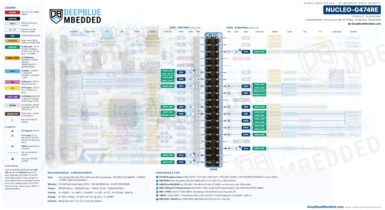
The Nucleo-G474RE has 5x 12-bit ADCs (up to 4Msps) with 26 external channels; 22 ADC pins are on the Morpho headers, and 13 of them are on the Arduino headers: A0–A5 plus D0, D1, D7, D8, D11, D12 and D13. The ADC reference is VREF+ (3.25v from the on-board reference by default, set by JP8).
| Arduino Pin | GPIO | ADC Channel | Header Pins |
|---|---|---|---|
| A0 | PA0 | ADC12_IN1 | CN8-1, CN7-28 |
| A1 | PA1 | ADC12_IN2 | CN8-2, CN7-30 |
| A2 | PA4 | ADC2_IN17 | CN8-3, CN7-32 |
| A3 | PB0 | ADC1_IN15, ADC3_IN12 | CN8-4, CN7-34 |
| A4 | PC1 | ADC12_IN7 | CN8-5, CN7-36 |
| A5 | PC0 | ADC12_IN6 | CN8-6, CN7-38 |
| D0 | PC5 | ADC2_IN11 | CN9-1, CN10-6/37 |
| D1 | PC4 | ADC2_IN5 | CN9-2, CN10-34/35 |
| D7 | PA8 | ADC5_IN1 | CN9-8, CN10-23 |
| D8 | PA9 | ADC5_IN2 | CN5-1, CN10-21 |
| D11 | PA7 | ADC2_IN4 | CN5-4, CN10-15 |
| D12 | PA6 | ADC2_IN3 | CN5-5, CN10-13 |
| D13 | PA5 | ADC2_IN13 (LED LD2) | CN5-6, CN10-11 |
| – | PB1 | ADC1_IN12, ADC3_IN1 | CN10-24 |
| – | PB2 | ADC2_IN12 | CN10-22 |
| – | PB11 | ADC12_IN14 | CN10-18 |
| – | PB12 | ADC1_IN11, ADC4_IN3 | CN10-16 |
| – | PB13 | ADC3_IN5 | CN10-30 |
| – | PB14 | ADC1_IN5, ADC4_IN4 | CN10-28 |
| – | PB15 | ADC2_IN15, ADC4_IN5 | CN10-26 |
| – | PC2 | ADC12_IN8 | CN7-35 |
| – | PC3 | ADC12_IN9 | CN7-37 |
Channels named ADC12 can be read by ADC1 or ADC2. ADC3 and ADC4 (PB1, PB12–PB15) and ADC5 (D7, D8) let you sample several signals at exactly the same time, like the phase currents of a motor or the voltage and current of a power converter. Each ADC also has hardware oversampling up to 16-bit, which is handy for slow, precise readings.
Note: A pin in analog mode is never 5v tolerant, so keep every ADC input between 0v and VREF+ (3.25v by default). Use a voltage divider to measure higher voltages, and remember that JP8 can switch VREF+ to VDD (3.3v) or, with SB14, to 2.5v.
There are so many sensors that we can read with the ADC pins, which include: potentiometers, current-sense shunts with the on-chip op-amps, NTC thermistors, LDRs, joysticks, battery voltage dividers, and much more.
Learn more in our STM32 ADC Tutorial series.
Also Read
Nucleo-G474RE DAC Pins
The Nucleo-G474RE has 3x 12-bit DAC outputs on pins: DAC1_OUT1 on A2 (PA4), DAC1_OUT2 on D13 (PA5) and DAC2_OUT1 on D12 (PA6). DAC3 and DAC4 have no pins: they feed the comparators and op-amps internally, for example as a comparator threshold.
| DAC Output | GPIO | Arduino Pin | Header Pins | Note |
|---|---|---|---|---|
| DAC1_OUT1 | PA4 | A2 | CN8-3, CN7-32 | Clean output, recommended |
| DAC1_OUT2 | PA5 | D13 | CN5-6, CN10-11 | Shares the pin with LED LD2 |
| DAC2_OUT1 | PA6 | D12 | CN5-5, CN10-13 | Also SPI1_MISO |
Note: D13 also drives the green LED LD2 through a transistor (SB6), so the LED glows with the DAC voltage. Use DAC1_OUT1 on A2 or DAC2_OUT1 on D12 for a clean output, or open SB6.
In the Arduino core, analogWrite() on a DAC pin uses the DAC instead of PWM.
Learn more in our STM32 DAC Tutorial series.
Also Read
Nucleo-G474RE Op-Amp & Comparator Pins
The Nucleo-G474RE has 6 op-amps (OPAMP1–OPAMP6, each usable as a PGA) and 7 comparators (COMP1–COMP7) inside the MCU. They’re what makes the G474 good at current sensing and overcurrent protection: an op-amp amplifies a shunt voltage straight into an ADC, and a comparator can shut down the PWM in nanoseconds.
| Op-Amp | Output (VOUT) | Non-inverting Inputs (VINP) | Inverting Inputs (VINM) |
|---|---|---|---|
| OPAMP1 | PA2 (VCP, not on a header) | A1 (PA1), PA3, D11 (PA7) | PA3, D0 (PC5) |
| OPAMP2 | D12 (PA6) | D11 (PA7), PB14, A3 (PB0) | D13 (PA5), D0 (PC5) |
| OPAMP3 | PB1 (CN10-24) | A3 (PB0), PB13, A1 (PA1) | PB2, D6 (PB10) |
| OPAMP4 | PB12 (CN10-16) | PB13, PB11 | D6 (PB10) |
| OPAMP5 | D7 (PA8) | PB14, PC3 | PB15, PA3 |
| OPAMP6 | PB11 (CN10-18) | PB12, PB13 | A1 (PA1), PB1 |
| Comparator | Input + (INP) | Outputs (OUT) |
|---|---|---|
| COMP1 | A1 (PA1), PB1 | A0 (PA0), D12 (PA6), PA11, D15 (PB8) |
| COMP2 | D11 (PA7), PA3 | PA2, D11 (PA7), PA12, D14 (PB9) |
| COMP3 | A0 (PA0), A4 (PC1) | PC2, PB7, PB15 |
| COMP4 | A3 (PB0) | PB1, D10 (PB6), PB14 |
| COMP5 | PB13 | D8 (PA9), D9 (PC7) |
| COMP6 | PB11 | D2 (PA10), PC6 |
| COMP7 | PB14 | D7 (PA8), PC8 |
The comparator’s negative input can be a pin or an internal source (a DAC3/DAC4 channel or a fraction of VREFINT), so you can set the trip level in software. A comparator output can also go straight to the HRTIM or TIM1/TIM8 fault and break inputs, without a pin at all.
Tip: PA2 and PA3 carry OPAMP1’s output and an input, but they’re wired to the STLINK-V3E Virtual COM port. Pick OPAMP2 (output on D12) or OPAMP5 (output on D7) for a quick test on the Arduino headers.
Learn more in our STM32 OpAmp (PGA) Tutorial.
Also Read
Learn more in our STM32 Comparator Tutorial.
Also Read
Nucleo-G474RE PWM Pins
The Nucleo-G474RE has 21 PWM pins on the Arduino headers (D0 and D2–D15, plus A0–A5) and 43 in total across the Morpho headers. The PWM pins are highlighted in orange in the pinout diagrams.
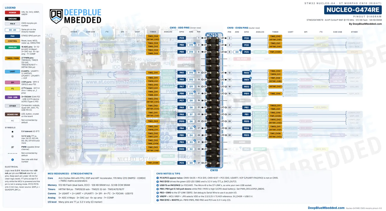
| Arduino Pin | GPIO | Timer Channels | Arduino Pin | GPIO | Timer Channels |
|---|---|---|---|---|---|
| D0 | PC5 | TIM1_CH4N | D10 | PB6 | TIM4_CH1, TIM8_CH1 |
| D2 | PA10 | TIM1_CH3, HRTIM1_CHB1 | D11 | PA7 | TIM3_CH2, TIM17_CH1 |
| D3 | PB3 | TIM2_CH2, TIM8_CH1N | D12 | PA6 | TIM3_CH1, TIM16_CH1 |
| D4 | PB5 | TIM3_CH2, TIM17_CH1 | D13 | PA5 | TIM2_CH1 |
| D5 | PB4 | TIM3_CH1, TIM16_CH1 | D14 | PB9 | TIM4_CH4, TIM8_CH3 |
| D6 | PB10 | TIM2_CH3 | D15 | PB8 | TIM4_CH3, TIM8_CH2 |
| D7 | PA8 | TIM1_CH1, HRTIM1_CHA1 | A0 | PA0 | TIM2_CH1, TIM5_CH1 |
| D8 | PA9 | TIM1_CH2, HRTIM1_CHA2 | A1 | PA1 | TIM2_CH2, TIM5_CH2 |
| D9 | PC7 | TIM3_CH2, TIM8_CH2, HRTIM1_CHF2 | A2 / A3 | PA4 / PB0 | TIM3_CH2 / TIM3_CH3 |
| A4 / A5 | PC1 / PC0 | TIM1_CH2 / TIM1_CH1 |
Pins on the same timer share its frequency, and some pins share the same channel: D13 and A0 can both be TIM2_CH1, and D11, D4 and A2 can all be TIM3_CH2. Two pins on one channel always output the same duty cycle, so pick another timer when you need them separately. TIM2 and TIM5 are 32-bit timers; the rest are 16-bit.
There are so many things that we can control with PWM, which include: LED dimming, DC motor speed (with a driver), servo motors, buzzers, ESCs for brushless motors, and much more.
Calculate your timer settings with this STM32 PWM Calculator.
Learn more in our STM32 PWM Tutorial series.

Also Read
Nucleo-G474RE HRTIM & Advanced Timer Pins
The Nucleo-G474RE has a high-resolution timer (HRTIM) with 6 timer units (A–F), 12 outputs and 184ps resolution, plus 3 advanced-control timers (TIM1, TIM8 and TIM20). All 12 HRTIM outputs are on the headers: CHA1 on D7, CHA2 on D8, CHB1 on D2 and CHF2 on D9 on the Arduino headers, and the rest on CN10.
| HRTIM Unit | Output 1 | Output 2 | Header Pins |
|---|---|---|---|
| Timer A | PA8 (D7) | PA9 (D8) | CN9-8 / CN5-1, CN10-23 / CN10-21 |
| Timer B | PA10 (D2) | PA11 | CN9-3, CN10-33 / CN10-14 |
| Timer C | PB12 | PB13 | CN10-16 / CN10-30 |
| Timer D | PB14 | PB15 | CN10-28 / CN10-26 |
| Timer E | PC8 | PC9 | CN10-2 / CN10-1 |
| Timer F | PC6 | PC7 (D9) | CN10-4 / CN5-2, CN10-19 |
Each HRTIM unit drives one half-bridge (output 1 and output 2 with dead-time), so the board can run up to 6 half-bridges at once. The HRTIM fault inputs on the headers are FLT1 PA12, FLT2 PA15, FLT3 PB10 (D6), FLT4 PB11, FLT5 PB0 (A3) or PC7 and FLT6 PC10, and the comparators can trigger faults internally.
For 3-phase motor control, TIM1 is the usual choice on the Nucleo-G474RE. Its main and complementary outputs land on these pins:
| Timer | CH1 / CH1N | CH2 / CH2N | CH3 / CH3N | CH4 | Break (BKIN) |
|---|---|---|---|---|---|
| TIM1 | PA8 (D7), PC0 (A5) / PA7 (D11), PA11, PB13, PC13 | PA9 (D8), PC1 (A4) / PA12, PB0 (A3), PB14 | PA10 (D2), PC2 / PB1, PB15, PB9 (D14) | PA11, PC3 | PA6, PA14, PA15, PB8, PB10, PB12, PC13 |
| TIM8 | PA15, PB6 (D10), PC6 / PA7, PB3 (D3), PC10 | PA14, PB8 (D15), PC7 (D9) / PB0, PB4 (D5), PC11 | PB9 (D14), PC8 / PB1, PB5 (D4), PC12 | PC9 | PA0, PA6, PA10, PB7, PD2 |
| TIM20 | PB2 | PC2 | PC8 | – | – |
A clean set for a 3-phase inverter is TIM1_CH1/2/3 on D7, D8, D2 with CH1N/2N/3N on PB13, PB14, PB15 (CN10-30, CN10-28, CN10-26).
Note: D7, D8 and D2 are shared by TIM1 and HRTIM Timer A/B, so you can use one or the other on those pins, not both. Also, PB13–PB15 are 3.3v-only TT pins: drive your gate driver with 3.3v logic.
Nucleo-G474RE UART Pins
The Nucleo-G474RE has 6 UARTs: USART1, USART2, USART3, UART4, UART5 and LPUART1. LPUART1 (PA2/PA3) is wired to the STLINK-V3E Virtual COM port, so printf reaches your PC through the USB cable, and D0/D1 are USART1 (PC5/PC4). This is different from the older Nucleo-64 boards, where the VCP was USART2.
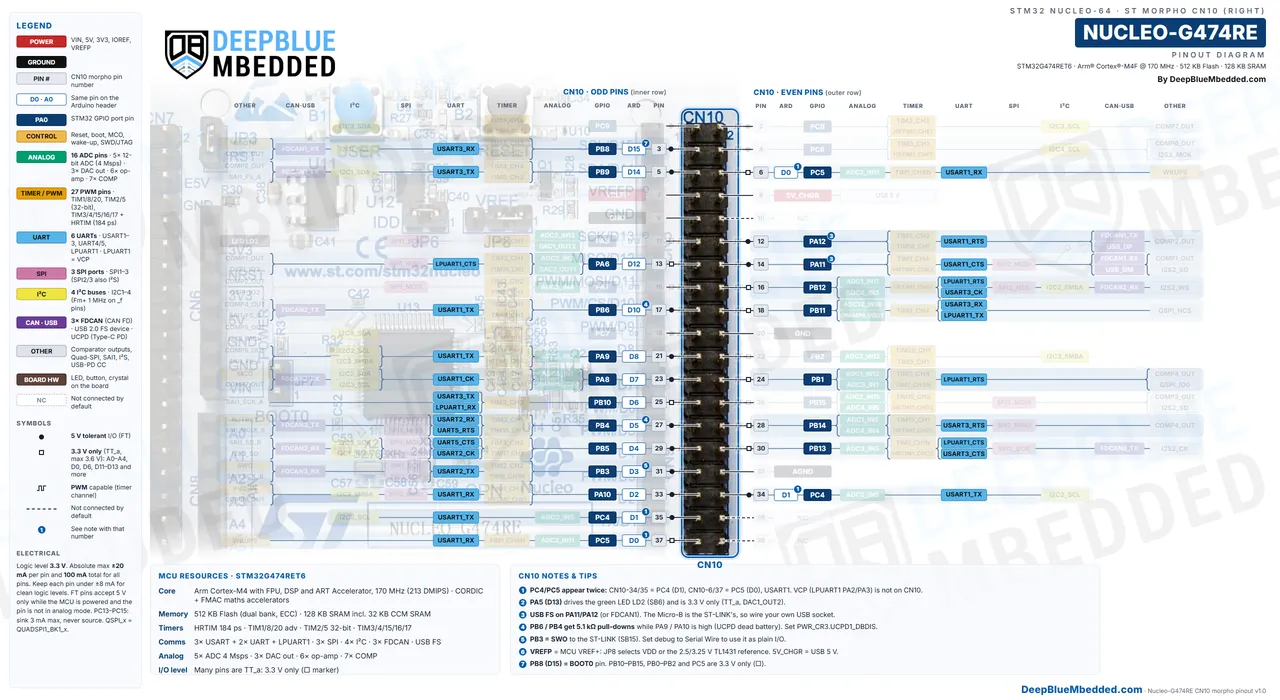
Nucleo-G474RE Default Serial (LPUART1): PA2 (TX) and PA3 (RX), to the PC over USB. Default Arduino UART (USART1): D1 = PC4 (TX) and D0 = PC5 (RX).
| UART | TX Pins | RX Pins | Note |
|---|---|---|---|
| LPUART1 | PA2 (VCP), PB11, A4 (PC1) | PA3 (VCP), D6 (PB10), A5 (PC0) | STLINK-V3E Virtual COM port |
| USART1 | D1 (PC4), D8 (PA9), D10 (PB6) | D0 (PC5), D2 (PA10), PB7 (CN7-21) | The Arduino UART on D0/D1 |
| USART2 | D3 (PB3), PA14 | D5 (PB4), PA15 | PA2/PA3 are taken by the VCP |
| USART3 | D14 (PB9), D6 (PB10), PC10 | D15 (PB8), PB11, PC11 | |
| UART4 | PC10 (CN7-1) | PC11 (CN7-2) | Morpho only |
| UART5 | PC12 (CN7-3) | PD2 (CN7-4) | Morpho only |
Note: If printf doesn’t show up in your terminal, check that you initialized LPUART1, not USART2. CubeMX does this for you when you start the project from the NUCLEO-G474RE board selector (ST Community).
There are so many modules that we can interface with the UART pins, which include: GPS modules, Bluetooth modules (HC-05), ESP8266/ESP32 Wi-Fi modules, RS485 transceivers, LIN transceivers, fingerprint sensors, and much more.
Learn more in our STM32 UART Tutorial series.
Also Read
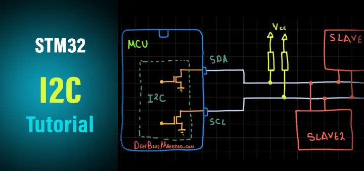
Nucleo-G474RE I2C Pins
The Nucleo-G474RE has 4x I2C buses (I2C1–I2C4), all of them up to Fast-mode Plus (1MHz) on the “_f” pins. The default I2C1 pins are D15 (PB8, SCL) and D14 (PB9, SDA), which are the Arduino Uno R3 SCL/SDA pins next to VREFP.
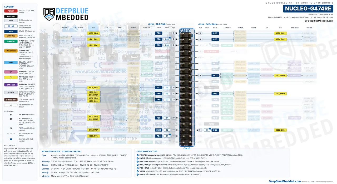
Nucleo-G474RE Default I2C1 Pins: D14 = PB9 (SDA) and D15 = PB8 (SCL).
| I2C Bus | SCL Pins | SDA Pins | Note |
|---|---|---|---|
| I2C1 | D15 (PB8), PA15, PA13 | D14 (PB9), PB7 (CN7-21), PA14 | Default Wire bus |
| I2C2 | D8 (PA9), D1 (PC4) | D7 (PA8), PF0 | |
| I2C3 | D7 (PA8), PC8 | D4 (PB5), PC9, PC11 | |
| I2C4 | PC6, PA13 | D9 (PC7), PB7 |
Note: A4 and A5 are not I2C pins on this board; they’re PC1 and PC0. Use D14/D15, or fit SB34/SB37 to add PB9/PA15 to A4/A5. There are no I2C pull-up resistors on the board, so add 2.2kΩ–4.7kΩ pull-ups to 3.3v unless your module has them. D15 is also BOOT0 (see below).
There are so many modules and sensors that we can interface with the I2C bus, which include: OLED displays (SSD1306), I2C LCDs, RTC modules (DS3231), IMUs (MPU6050), BME280 sensors, EEPROMs, and much more.
Learn more in our STM32 I2C Tutorial series.
Also Read
Nucleo-G474RE SPI Pins
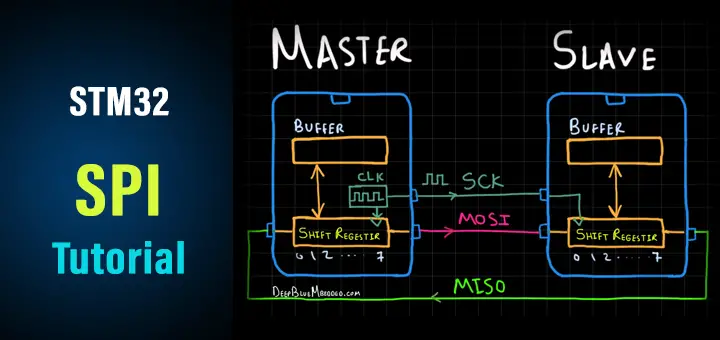
The Nucleo-G474RE has 3x SPI ports (SPI1, SPI2, SPI3), and SPI2/SPI3 can also be I²S. The default SPI1 pins are D13 (SCK), D12 (MISO) and D11 (MOSI), just like on an Arduino Uno.
Nucleo-G474RE Default SPI1 Pins: D13 = PA5 (SCK), D12 = PA6 (MISO), D11 = PA7 (MOSI), and any GPIO (usually D10) as CS.
| SPI Port | SCK | MISO | MOSI | NSS |
|---|---|---|---|---|
| SPI1 | D13 (PA5), D3 (PB3) | D12 (PA6), D5 (PB4) | D11 (PA7), D4 (PB5) | A2 (PA4), PA15 |
| SPI2 | PB13, PF1 | D2 (PA10), PB14 | PA11, PB15 | PB12, PF0 |
| SPI3 | D3 (PB3), PC10 | D5 (PB4), PC11 | D4 (PB5), PC12 | A2 (PA4), PA15 |
Note: D13 (SPI1_SCK) also drives the green LED LD2, so the LED flickers during SPI transfers. That’s normal. SPI3 on D3/D5/D4 is a second SPI right on the Arduino header.
There are so many modules that we can interface with the SPI bus, which include: TFT displays (ILI9341, ST7735), SD card modules, nRF24L01 radios, MAX7219 LED drivers, W5500 Ethernet modules, and much more.
Learn more in our STM32 SPI Tutorial series.
Also Read
Nucleo-G474RE CAN (FDCAN) Pins
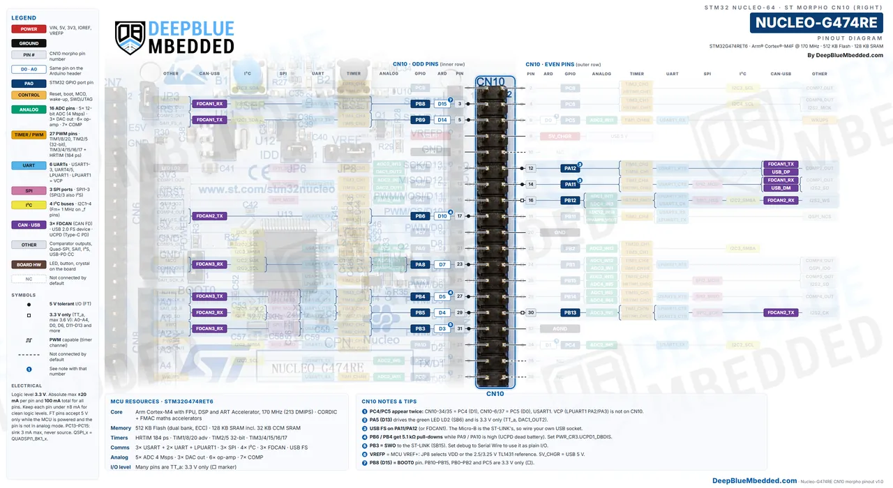
The Nucleo-G474RE has 3x FDCAN controllers that support both classic CAN 2.0 and CAN FD (up to 64-byte payloads, faster data phase). FDCAN1 is on D15 (PB8, RX) and D14 (PB9, TX), the same pins as I2C1.
| FDCAN | RX Pins | TX Pins |
|---|---|---|
| FDCAN1 | D15 (PB8), PA11 (CN10-14) | D14 (PB9), PA12 (CN10-12) |
| FDCAN2 | D4 (PB5), PB12 (CN10-16) | D10 (PB6), PB13 (CN10-30) |
| FDCAN3 | D7 (PA8), D3 (PB3) | PA15 (CN7-17), D5 (PB4) |
Note: The board has no CAN transceiver. Connect a 3.3v CAN FD transceiver (TCAN330, MCP2562FD with VIO at 3.3v…) between the pins and the bus. Also, PB6 (FDCAN2_TX) can be pulled LOW at reset by the UCPD dead-battery pull-down; call HAL_PWREx_DisableUCPDDeadBattery() early in main() (ST Community).
D14/D15 can be I2C1 or FDCAN1, never both at once. If you need both, move FDCAN1 to PA11/PA12 (and give up USB) or use FDCAN2 on D4/D10.
Nucleo-G474RE USB & USB-C (UCPD) Pins
The STM32G474RE has a USB 2.0 full-speed device and a USB Type-C Power Delivery controller (UCPD), but the Nucleo-G474RE’s Micro-B connector only goes to the STLINK-V3E. To use the MCU’s own USB, wire a USB connector to PA11 (D−) and PA12 (D+) on CN10. The UCPD CC lines are on D10 (PB6, CC1) and D5 (PB4, CC2).
| Signal | GPIO | Header Pins | Note |
|---|---|---|---|
| USB_DM (D−) | PA11 | CN10-14 | USB FS device, on-chip PHY |
| USB_DP (D+) | PA12 | CN10-12 | Internal 1.5kΩ pull-up |
| UCPD1_CC1 | PB6 | D10, CN10-17 | Type-C configuration channel 1 |
| UCPD1_CC2 | PB4 | D5, CN10-27 | Type-C configuration channel 2 |
| UCPD1_DBCC1 | PA9 | D8, CN10-21 | Dead-battery control for CC1 |
| UCPD1_DBCC2 | PA10 | D2, CN10-33 | Dead-battery control for CC2 |
The USB peripheral needs an accurate 48MHz clock. You can get it from the PLL with the 24MHz crystal, or from the internal HSI48 trimmed by the CRS (clock recovery system) from the USB SOF packets. For USB-C power delivery, ST’s USB Type-C expansion shields (like the X-NUCLEO-SNK1M1) plug into the Arduino headers and use these CC pins.
Note: The UCPD dead-battery feature turns on 5.1kΩ pull-downs on PB4 (D5) and PB6 (D10) whenever PA9 (D8) or PA10 (D2) is HIGH. If D5 or D10 won’t go HIGH, that’s the cause. Disable it with HAL_PWREx_DisableUCPDDeadBattery() (PWR_CR3.UCPD1_DBDIS = 1).
Learn more in our STM32 USB CDC Tutorial.
Also Read
Nucleo-G474RE Debug (SWD) & Boot Pins
The Nucleo-G474RE is programmed and debugged over SWD on PA13 (SWDIO) and PA14 (SWCLK), with PB3 (SWO) for trace output, all wired to the on-board STLINK-V3E. The boot pin is PB8-BOOT0, which is also D15 and CN7-7.
| Pin | Header Pin | Function After Reset |
|---|---|---|
| PA13 | CN7-13 | SWDIO (JTMS), pull-up |
| PA14 | CN7-15 | SWCLK (JTCK), pull-down |
| PB3 | D3, CN10-31 | SWO (JTDO), to the STLINK-V3E via SB15 |
| PA15 | CN7-17 | JTDI, pull-up (to CN4 via SB9) |
| PB4 | D5, CN10-27 | NJTRST, pull-up |
| NRST (PG10) | CN6-3, CN7-14 | Reset (B2 button, STLINK-V3E) |
| PB8-BOOT0 | D15, CN10-3, CN7-7 | GPIO or BOOT0, set by option bytes; JP7 adds a pull-down |
On the STM32G4, the boot mode comes from the nBOOT1 option bit plus either the PB8-BOOT0 pin or the nBOOT0 option bit; the nSWBOOT0 option bit decides which. UM2505 states that BOOT0 isn’t connected by default on this board and that the boot function is handled by the option bytes. PB8 reaches both D15 (SB2) and CN7-7 (SB4) by default, and jumper JP7 (open by default) adds a pull-down to it.
| nSWBOOT0 | Boot Source | PB8 (D15) |
|---|---|---|
| 0 | nBOOT0 option bit (1 = main Flash) | Free GPIO at reset |
| 1 | The PB8-BOOT0 pin (LOW = main Flash, HIGH = system bootloader with nBOOT1 = 1) | Must be LOW at reset to run your code; fit JP7 |
Note: If your Nucleo-G474RE sometimes starts the ST bootloader instead of your program, or your I2C pull-up on D15 stops it from booting, open STM32CubeProgrammer → Option Bytes → User Configuration and check nSWBOOT0. Clear it (with nBOOT0 = 1) to free PB8 as a normal I/O (ST Community).
To start the system bootloader on purpose, set nSWBOOT0 = 1, tie D15 (CN7-7) to 3.3v and reset the board. The G474 bootloader supports USART1/2/3, LPUART1, I2C2/3, SPI1/2, FDCAN1 and USB DFU (ST application note AN2606). To debug another board with the on-board STLINK-V3E, fit JP1 to hold it off the local MCU and use the 14-pin CN4 STDC14 connector.
Learn more in our STM32 SWD Debugging Tutorial.
Also Read
Nucleo-G474RE On-Board Features
Besides the headers, the Nucleo-G474RE has 4 LEDs, 2 buttons, two crystals, a few jumpers, and 41 solder bridges. Here’s what each one does.
| Part | Pin / Connection | What It Does |
|---|---|---|
| LD1 COM (red/green) | STLINK-V3E | Blinking red: USB enumeration. Red: ready. Blinking red/green: communicating. Green: success. Orange: communication failure |
| LD2 USER (green) | PA5 / D13 (SB6) | HIGH = on (through a transistor) |
| LD3 5V_PWR (green) | +5V | The board has 5v |
| LD4 OC (red) | STLINK USB | USB overcurrent (more than 500mA) |
| B1 USER (blue) | PC13 (SB16) | Wired to VDD with a 100kΩ pull-down: reads HIGH when pressed |
| B2 RESET (black) | NRST | Resets the MCU |
| X3 | PF0/PF1 | 24MHz HSE crystal |
| X2 | PC14/PC15 | 32.768kHz LSE crystal for the RTC |
| JP1 | STLINK-V3E | ON: holds the STLINK-V3E in reset (for an external probe on CN4) |
| JP5 | Power select | 5V_STLK (default), 5V_VIN, E5V or 5V_CHGR |
| JP6 (IDD) | MCU supply | Remove it and insert an ammeter to measure the MCU current |
| JP7 | PB8-BOOT0 | Open by default; fit it to pull BOOT0 LOW |
| JP8 | VREF+ | On-board reference (3.25v default, 2.5v with SB14) or VDD |
Nucleo-G474RE Solder Bridges
These are the solder bridges you’re most likely to change (UM2505 Table 12, defaults in bold there):
| Bridge | Default | Effect |
|---|---|---|
| SB17, SB23 | ON | LPUART1 (PA2/PA3) to the STLINK-V3E Virtual COM port |
| SB18, SB22 | OFF | PA2/PA3 not on D1/D0 |
| SB13, SB19 | ON | USART1 (PC4/PC5) on D1/D0 |
| SB12, SB20 | OFF | USART1 not on the Virtual COM port (swap with SB17/SB23 to move the VCP) |
| SB35, SB36 | ON | A4 = PC1, A5 = PC0 |
| SB34, SB37 | OFF | Close for I2C1 (PB9/PA15) on A4/A5 |
| SB2, SB4 | ON | PB8 on D15 and CN7-7 |
| SB6 | ON | LED LD2 on PA5 |
| SB16 | ON | B1 button on PC13 (SB21 moves it to PA0) |
| SB15 | ON | SWO (PB3) to the STLINK-V3E |
| SB25, SB26 | ON | 24MHz crystal X3 on PF0/PF1 (SB24/SB28 OFF: not on CN7) |
| SB30, SB31 | ON | 32.768kHz crystal X2 on PC14/PC15 (SB29/SB32 OFF: not on CN7) |
| SB38 | ON | VBAT = VDD |
| SB39 | ON | IOREF = 3.3v |
| SB3, SB33 | ON | PC5 on CN10-6, PC4 on CN10-34 |
Getting Started With Nucleo-G474RE
You can program the Nucleo-G474RE with any of the common STM32 toolchains, and the STLINK-V3E on board means you don’t need anything else besides a Micro-USB cable.
- STM32CubeIDE: start a new project from the Board Selector, pick NUCLEO-G474RE, and let CubeMX set up LD2, B1 and LPUART1 for you. For the full 170MHz, run the PLL from the 24MHz HSE and enable the boost mode (Range 1 boost).
- Arduino IDE (STM32duino): install “STM32 MCU based boards”, then choose Board: “Nucleo-64” and Board part number: “Nucleo G474RE”.
- PlatformIO: board ID nucleo_g474re, with the STM32Cube, Arduino or Zephyr framework.
- Zephyr RTOS: board name nucleo_g474re.
- Drag-and-drop: the board shows up as a USB drive; copy a .bin file onto it to flash it.
| Arduino Name | Pin | Default |
|---|---|---|
Serial | PA2 / PA3 (LPUART1) | To the PC through the STLINK-V3E |
Wire | PB9 (SDA, D14), PB8 (SCL, D15) | I2C1 |
SPI | D13 / D12 / D11 | SPI1 |
LED_BUILTIN | PA5 (D13) | LD2 |
USER_BTN | PC13 | B1 (HIGH when pressed) |
Here’s the classic first test, blinking LD2 and printing the button state to the Serial Monitor at 115200 baud:
|
1 2 3 4 5 6 7 8 9 10 11 |
void setup() { pinMode(LED_BUILTIN, OUTPUT); // LD2 on PA5 (D13) pinMode(USER_BTN, INPUT); // B1 on PC13, HIGH when pressed Serial.begin(115200); // LPUART1 to the STLINK-V3E VCP } void loop() { digitalWrite(LED_BUILTIN, !digitalRead(LED_BUILTIN)); Serial.println(digitalRead(USER_BTN) ? "B1 pressed" : "B1 released"); delay(500); } |
With STM32CubeIDE and HAL, the same blink is HAL_GPIO_TogglePin(GPIOA, GPIO_PIN_5); in the main loop. Follow the STM32 LED Blink Code Example for the full walk-through, and set up the clock tree with the STM32 RCC Clock Configuration Guide.
Nucleo-G474RE Common Problems & Fixes
Why doesn’t printf show up on my PC? The Virtual COM port is LPUART1 on PA2/PA3, not USART2 like on other Nucleo-64 boards. Initialize LPUART1 and retarget printf to it (ST Community).
Why doesn’t my shield’s serial work on D0/D1? D0/D1 are USART1 (PC5/PC4), so configure USART1, not the VCP UART. In Arduino, create HardwareSerial Serial1(PC5, PC4); for them.
Why is PB4 (D5) always HIGH? It’s NJTRST after reset, with an internal pull-up. Set debug to Serial Wire to free it (ST Community).
Why are PB6 (D10) and PB4 (D5) pulled LOW? The UCPD dead-battery pull-downs are on while PA9/PA10 are HIGH. Call HAL_PWREx_DisableUCPDDeadBattery().
Why does the button read the opposite of what I expect? B1 on this board reads HIGH when pressed (it’s wired to VDD), unlike the F4 Nucleo-64 boards where it reads LOW.
Why doesn’t my I2C shield respond on A4/A5? A4/A5 are PC1/PC0, not I2C pins. Use D14 (SDA) and D15 (SCL) with pull-ups, or fit SB34/SB37.
Why does my board start the bootloader instead of my program? PB8 (D15) is BOOT0. If nSWBOOT0 = 1 and something pulls D15 HIGH at reset, the bootloader runs. Clear nSWBOOT0 in STM32CubeProgrammer or fit JP7.
Why did a 5v sensor damage A0 or D13? A0–A4, D0, D6 and D11–D13 are 3.3v-only TT pins on the G474RE. Use a level shifter on those pins.
Why doesn’t USART3 work on PB10/PB11? Users report it was fixed by updating STM32CubeMX and the HAL/LL drivers; it works on PC10/PC11 meanwhile (ST Community).
Nucleo-G474RE vs Nucleo-F446RE
The Nucleo-G474RE and the Nucleo-F446RE have the same Nucleo-64 shape and Arduino/Morpho header positions, but a different PCB (MB1367 vs MB1136), a different debugger, and very different MCUs:
| Feature | Nucleo-F446RE | Nucleo-G474RE |
|---|---|---|
| MCU clock | 180MHz | 170MHz |
| Flash / RAM | 512KB / 128KB | 512KB / 128KB |
| ADC | 3x 12-bit, 2.4Msps | 5x 12-bit, 4Msps |
| DAC outputs | 2 | 3 (+4 internal) |
| Op-amps / comparators | No | 6 / 7 |
| High-resolution timer | No | HRTIM, 184ps, 12 outputs |
| CAN | 2x CAN 2.0B | 3x FDCAN (CAN FD) |
| USB | OTG FS + OTG HS | FS device + UCPD (Type-C PD) |
| Debugger | ST-LINK/V2-1, Mini-B | STLINK-V3E, Micro-B |
| Virtual COM port | USART2 (PA2/PA3) | LPUART1 (PA2/PA3) |
| D0/D1 | Not connected by default | USART1 (PC5/PC4) |
| HSE clock | 8MHz MCO from the ST-LINK | 24MHz crystal |
| B1 button | LOW when pressed | HIGH when pressed |
| 3.3v-only header pins | 2 (A2, D13) | 10 on the Arduino headers |
Pick the Nucleo-G474RE for power conversion, motor control and anything analog-heavy: HRTIM, the op-amps and comparators, and CAN FD are the reasons to buy it. Pick the Nucleo-F446RE when you need more 5v-tolerant pins, USB OTG host, or the extra 10MHz.
Nucleo-G474RE Pin Details
Here is every Nucleo-G474RE header pin in physical order, with its main functions, all its alternate functions, its 5v tolerance, and a short description. The Arduino headers come first, then the two ST Morpho headers.
Nucleo-G474RE Arduino Header Pins (CN5, CN6, CN8, CN9)
| Pin | Label | GPIO | Main Functions | All Alternate Functions | 5v Tolerant | Description |
|---|---|---|---|---|---|---|
| CN6-1 | NC | – | – | – | – | Not connected. |
| CN6-2 | IOREF | – | 3.3v (SB39) | – | – | 3.3v I/O reference for shields (SB39). |
| CN6-3 | RESET | – | NRST | – | – | NRST: pull it LOW to reset the MCU. |
| CN6-4 | 3V3 | – | 3.3v in/out | – | – | 3.3v output from the LD39050 regulator (500mA), or a 3.0v–3.6v input. |
| CN6-5 | 5V | – | 5v out | – | – | 5v output from USB, VIN or E5V. |
| CN6-6 | GND | – | – | – | – | Ground. |
| CN6-7 | GND | – | – | – | – | Ground. |
| CN6-8 | VIN | – | 7v–12v in | – | – | 7v–12v input to the LD1117 5v regulator (JP5 on VIN). |
| CN8-1 | A0 | PA0 | ADC12_IN1, TIM2_CH1, TIM5_CH1, USART2_CTS, WKUP1, COMP1_OUT | TIM2_CH1, TIM5_CH1, USART2_CTS, USART2_NSS, COMP1_OUT, TIM8_BKIN, TIM8_ETR, TIM2_ETR, ADC1_IN1, ADC2_IN1, COMP1_INM, COMP3_INP, RTC_TAMP2, SYS_WKUP1 | No (3.3v only) | A0 analog input (ADC12_IN1), WKUP1 and TIM2/TIM5 channel 1 PWM; 3.3v only. |
| CN8-2 | A1 | PA1 | ADC12_IN2, TIM2_CH2, TIM5_CH2, USART2_RTS | RTC_REFIN, TIM2_CH2, TIM5_CH2, USART2_DE, USART2_RTS, TIM15_CH1N, ADC1_IN2, ADC2_IN2, COMP1_INP, OPAMP1_VINP, OPAMP1_VINP_SEC, OPAMP3_VINP, OPAMP3_VINP_SEC, OPAMP6_VINM, OPAMP6_VINM0, OPAMP6_VINM_SEC | No (3.3v only) | A1 analog input (ADC12_IN2), OPAMP1/OPAMP3 input and TIM2/TIM5 channel 2 PWM; 3.3v only. |
| CN8-3 | A2 | PA4 | ADC2_IN17, DAC1_OUT1, TIM3_CH2, USART2_CK, SPI1_NSS, SPI3_NSS, SAI1_FS_B, I2S3_WS | TIM3_CH2, SPI1_NSS, I2S3_WS, SPI3_NSS, USART2_CK, SAI1_FS_B, ADC2_IN17, COMP1_INM, DAC1_OUT1 | No (3.3v only) | A2 analog input and DAC1_OUT1, the cleanest DAC output on the board; 3.3v only. |
| CN8-4 | A3 | PB0 | ADC1_IN15, ADC3_IN12, TIM3_CH3, TIM1_CH2N, QSPI_IO1 | TIM3_CH3, TIM8_CH2N, TIM1_CH2N, QUADSPI1_BK1_IO1, HRTIM1_FLT5, UCPD1_FRSTX1, UCPD1_FRSTX2, ADC1_IN15, ADC3_IN12, COMP4_INP, OPAMP2_VINP, OPAMP2_VINP_SEC, OPAMP3_VINP, OPAMP3_VINP_SEC | No (3.3v only) | A3 analog input (ADC1_IN15, ADC3_IN12), OPAMP2/OPAMP3 input and TIM3_CH3/TIM1_CH2N; 3.3v only. |
| CN8-5 | A4 | PC1 | ADC12_IN7, TIM1_CH2, LPUART1_TX, SAI1_SD_A | LPTIM1_OUT, TIM1_CH2, LPUART1_TX, QUADSPI1_BK2_IO0, SAI1_SD_A, ADC1_IN7, ADC2_IN7, COMP3_INP | No (3.3v only) | A4 analog input (ADC12_IN7), TIM1_CH2 and LPUART1_TX; 3.3v only, and not I2C by default. |
| CN8-6 | A5 | PC0 | ADC12_IN6, TIM1_CH1, LPUART1_RX | LPTIM1_IN1, TIM1_CH1, LPUART1_RX, ADC1_IN6, ADC2_IN6, COMP3_INM | Yes | A5 analog input (ADC12_IN6), TIM1_CH1 and LPUART1_RX; 5v tolerant as a digital pin. |
| CN5-10 | D15 | PB8 | TIM4_CH3, TIM8_CH2, USART3_RX, I2C1_SCL, FDCAN1_RX, BOOT0, COMP1_OUT | TIM16_CH1, TIM4_CH3, SAI1_CK1, I2C1_SCL, USART3_RX, COMP1_OUT, FDCAN1_RX, TIM8_CH2, TIM1_BKIN, HRTIM1_EEV8, SAI1_MCLK_A | Yes | D15 and CN7-7: the default I2C1_SCL (Wire), FDCAN1_RX and TIM4_CH3; also the BOOT0 pin. |
| CN5-9 | D14 | PB9 | TIM4_CH4, TIM8_CH3, USART3_TX, I2C1_SDA, FDCAN1_TX, COMP2_OUT, SAI1_FS_A | TIM17_CH1, TIM4_CH4, SAI1_D2, I2C1_SDA, IR_OUT, USART3_TX, COMP2_OUT, FDCAN1_TX, TIM8_CH3, TIM1_CH3N, HRTIM1_EEV5, SAI1_FS_A, DAC1_EXTI9, DAC2_EXTI9, DAC3_EXTI9, DAC4_EXTI9 | Yes | D14: the default I2C1_SDA (Wire), FDCAN1_TX, USART3_TX and TIM4_CH4 PWM. |
| CN5-8 | VREFP | – | VREF+ (JP8) | – | – | MCU VREF+: 3.25v (or 2.5v) reference or VDD, set by JP8. |
| CN5-7 | GND | – | – | – | – | Ground. |
| CN5-6 | D13 | PA5 | ADC2_IN13, DAC1_OUT2, TIM2_CH1, SPI1_SCK, LED LD2 | TIM2_CH1, TIM2_ETR, SPI1_SCK, UCPD1_FRSTX1, UCPD1_FRSTX2, ADC2_IN13, COMP2_INM, DAC1_OUT2, OPAMP2_VINM, OPAMP2_VINM0, OPAMP2_VINM_SEC | No (3.3v only) | D13: drives the green user LED LD2 (SB6), SPI1_SCK, DAC1_OUT2 and TIM2_CH1; 3.3v only. |
| CN5-5 | D12 | PA6 | ADC2_IN3, DAC2_OUT1, TIM3_CH1, TIM16_CH1, LPUART1_CTS, SPI1_MISO, COMP1_OUT, QSPI_IO3 | TIM16_CH1, TIM3_CH1, TIM8_BKIN, SPI1_MISO, TIM1_BKIN, COMP1_OUT, QUADSPI1_BK1_IO3, LPUART1_CTS, ADC2_IN3, DAC2_OUT1, OPAMP2_VOUT | No (3.3v only) | D12: SPI1_MISO, DAC2_OUT1, OPAMP2 output and TIM3_CH1/TIM16_CH1 PWM; 3.3v only. |
| CN5-4 | D11 | PA7 | ADC2_IN4, TIM3_CH2, TIM17_CH1, SPI1_MOSI, COMP2_OUT, QSPI_IO2 | TIM17_CH1, TIM3_CH2, TIM8_CH1N, SPI1_MOSI, TIM1_CH1N, COMP2_OUT, QUADSPI1_BK1_IO2, UCPD1_FRSTX1, UCPD1_FRSTX2, ADC2_IN4, COMP2_INP, OPAMP1_VINP, OPAMP1_VINP_SEC, OPAMP2_VINP, OPAMP2_VINP_SEC | No (3.3v only) | D11: SPI1_MOSI, ADC2_IN4, COMP2 input and TIM3_CH2/TIM17_CH1 PWM; 3.3v only. |
| CN5-3 | D10 | PB6 | TIM4_CH1, TIM8_CH1, USART1_TX, FDCAN2_TX, COMP4_OUT, SAI1_FS_B | TIM16_CH1N, TIM4_CH1, TIM8_CH1, TIM8_ETR, USART1_TX, COMP4_OUT, FDCAN2_TX, TIM8_BKIN2, LPTIM1_ETR, HRTIM1_SCIN, HRTIM1_EEV4, SAI1_FS_B, UCPD1_CC1 | Yes | D10: UCPD1_CC1, USART1_TX, FDCAN2_TX and TIM4_CH1/TIM8_CH1 PWM. |
| CN5-2 | D9 | PC7 | TIM3_CH2, HRTIM1_CHF2, I2C4_SDA, COMP5_OUT, I2S3_MCK | TIM3_CH2, HRTIM1_FLT5, TIM8_CH2, I2S3_MCK, COMP5_OUT, I2C4_SDA, HRTIM1_CHF2 | Yes | D9: HRTIM1_CHF2, TIM3_CH2/TIM8_CH2, I2C4_SDA and COMP5_OUT. |
| CN5-1 | D8 | PA9 | ADC5_IN2, TIM1_CH2, HRTIM1_CHA2, USART1_TX, I2C2_SCL, I2C3_SMBA, COMP5_OUT, SAI1_FS_A | I2C3_SMBA, I2C2_SCL, I2S3_MCK, TIM1_CH2, USART1_TX, COMP5_OUT, TIM15_BKIN, TIM2_CH3, HRTIM1_CHA2, SAI1_FS_A, ADC5_IN2, DAC1_EXTI9, DAC2_EXTI9, DAC3_EXTI9, DAC4_EXTI9, UCPD1_DBCC1 | Yes | D8: HRTIM1_CHA2, TIM1_CH2 and USART1_TX; driving it HIGH enables the UCPD dead-battery pull-down on PB6. |
| CN9-8 | D7 | PA8 | ADC5_IN1, OPAMP5_VOUT, TIM1_CH1, HRTIM1_CHA1, USART1_CK, I2C2_SDA, I2C3_SCL, FDCAN3_RX, MCO, COMP7_OUT | RCC_MCO, I2C3_SCL, I2C2_SDA, I2S2_MCK, TIM1_CH1, USART1_CK, COMP7_OUT, TIM4_ETR, FDCAN3_RX, SAI1_CK2, HRTIM1_CHA1, SAI1_SCK_A, ADC5_IN1, OPAMP5_VOUT | Yes | D7: HRTIM1_CHA1, TIM1_CH1, OPAMP5 output, FDCAN3_RX and the MCO clock output. |
| CN9-7 | D6 | PB10 | TIM2_CH3, USART3_TX, LPUART1_RX, SAI1_SCK_A | TIM2_CH3, USART3_TX, LPUART1_RX, QUADSPI1_CLK, TIM1_BKIN, HRTIM1_FLT3, SAI1_SCK_A, COMP5_INM, DAC1_EXTI10, DAC2_EXTI10, DAC3_EXTI10, DAC4_EXTI10, OPAMP3_VINM, OPAMP3_VINM1, OPAMP3_VINM_SEC, OPAMP4_VINM, OPAMP4_VINM0, OPAMP4_VINM_SEC | No (3.3v only) | D6: TIM2_CH3 PWM, USART3_TX, LPUART1_RX and HRTIM1_FLT3; 3.3v only. |
| CN9-6 | D5 | PB4 | TIM3_CH1, TIM16_CH1, USART2_RX, UART5_RTS, SPI1_MISO, SPI3_MISO, FDCAN3_TX, NJTRST, SAI1_MCLK_B | SYS_JTRST, TIM16_CH1, TIM3_CH1, TIM8_CH2N, SPI1_MISO, SPI3_MISO, USART2_RX, UART5_DE, UART5_RTS, TIM17_BKIN, FDCAN3_TX, HRTIM1_EEV7, SAI1_MCLK_B, UCPD1_CC2 | Yes | D5: NJTRST (pull-up) after reset and UCPD1_CC2, then SPI1/SPI3_MISO, TIM3_CH1 or FDCAN3_TX. |
| CN9-5 | D4 | PB5 | TIM3_CH2, TIM17_CH1, UART5_CTS, USART2_CK, SPI1_MOSI, SPI3_MOSI, I2C3_SDA, I2C1_SMBA, FDCAN2_RX, SAI1_SD_B, I2S3_SD | TIM16_BKIN, TIM3_CH2, TIM8_CH3N, I2C1_SMBA, SPI1_MOSI, I2S3_SD, SPI3_MOSI, USART2_CK, I2C3_SDA, FDCAN2_RX, TIM17_CH1, LPTIM1_IN1, SAI1_SD_B, HRTIM1_EEV6, UART5_CTS | Yes | D4: SPI1/SPI3_MOSI, I2C3_SDA, FDCAN2_RX and TIM3_CH2/TIM17_CH1 PWM. |
| CN9-4 | D3 | PB3 | TIM2_CH2, TIM8_CH1N, USART2_TX, SPI1_SCK, SPI3_SCK, FDCAN3_RX, SWO, SAI1_SCK_B | SYS_JTDO-SWO, TIM2_CH2, TIM4_ETR, CRS_SYNC, TIM8_CH1N, SPI1_SCK, I2S3_CK, SPI3_SCK, USART2_TX, TIM3_ETR, FDCAN3_RX, HRTIM1_SCOUT, HRTIM1_EEV9, SAI1_SCK_B, ADC3_EXTI3, ADC4_EXTI3, ADC5_EXTI3 | Yes | D3: SWO trace output to the STLINK-V3E (SB15), then SPI1/SPI3_SCK, TIM2_CH2 or FDCAN3_RX. |
| CN9-3 | D2 | PA10 | TIM1_CH3, HRTIM1_CHB1, USART1_RX, SPI2_MISO, I2C2_SMBA, PVD_IN, COMP6_OUT | TIM17_BKIN, CRS_SYNC, I2C2_SMBA, SPI2_MISO, TIM1_CH3, USART1_RX, COMP6_OUT, TIM2_CH4, TIM8_BKIN, SAI1_D1, HRTIM1_CHB1, SAI1_SD_A, DAC1_EXTI10, DAC2_EXTI10, DAC3_EXTI10, DAC4_EXTI10, SYS_PVD_IN, UCPD1_DBCC2 | Yes | D2: HRTIM1_CHB1, TIM1_CH3 and USART1_RX; driving it HIGH enables the UCPD dead-battery pull-down on PB4. |
| CN9-2 | D1 | PC4 | ADC2_IN5, USART1_TX, I2C2_SCL | TIM1_ETR, I2C2_SCL, USART1_TX, QUADSPI1_BK2_IO3, ADC2_IN5 | Yes | D1: USART1_TX (the default header serial TX), I2C2_SCL and ADC2_IN5; also on CN10-34 and CN10-35. |
| CN9-1 | D0 | PC5 | ADC2_IN11, TIM1_CH4N, USART1_RX, WKUP5 | TIM15_BKIN, SAI1_D3, TIM1_CH4N, USART1_RX, HRTIM1_EEV10, ADC2_IN11, OPAMP1_VINM, OPAMP1_VINM1, OPAMP1_VINM_SEC, OPAMP2_VINM, OPAMP2_VINM1, OPAMP2_VINM_SEC, SYS_WKUP5 | No (3.3v only) | D0: USART1_RX (the default header serial RX), ADC2_IN11 and WKUP5; 3.3v only; also on CN10-6 and CN10-37. |
Nucleo-G474RE Morpho CN7 Pins
On CN7, pin 1 is at the end nearest the STLINK-V3E, and odd pins are on the outer column.
| Pin | Label | GPIO | Main Functions | All Alternate Functions | 5v Tolerant | Description |
|---|---|---|---|---|---|---|
| CN7-1 | – | PC10 | TIM8_CH1N, UART4_TX, USART3_TX, SPI3_SCK, I2S3_CK | TIM8_CH1N, UART4_TX, I2S3_CK, SPI3_SCK, USART3_TX, HRTIM1_FLT6, DAC1_EXTI10, DAC2_EXTI10, DAC3_EXTI10, DAC4_EXTI10 | Yes | Morpho only: UART4_TX/USART3_TX, SPI3_SCK and TIM8_CH1N. |
| CN7-2 | – | PC11 | TIM8_CH2N, UART4_RX, USART3_RX, SPI3_MISO, I2C3_SDA | HRTIM1_EEV2, TIM8_CH2N, UART4_RX, SPI3_MISO, USART3_RX, I2C3_SDA, ADC1_EXTI11, ADC2_EXTI11 | Yes | Morpho only: UART4_RX/USART3_RX, SPI3_MISO and I2C3_SDA. |
| CN7-3 | – | PC12 | TIM5_CH2, TIM8_CH3N, UART5_TX, USART3_CK, SPI3_MOSI, I2S3_SD | TIM5_CH2, HRTIM1_EEV1, TIM8_CH3N, UART5_TX, I2S3_SD, SPI3_MOSI, USART3_CK, UCPD1_FRSTX1, UCPD1_FRSTX2 | Yes | Morpho only: UART5_TX, SPI3_MOSI and TIM8_CH3N. |
| CN7-4 | – | PD2 | UART5_RX | TIM3_ETR, TIM8_BKIN, UART5_RX, ADC3_EXTI2, ADC4_EXTI2, ADC5_EXTI2 | Yes | Morpho only: UART5_RX and TIM3_ETR. |
| CN7-5 | VDD | – | 3.3v (VDD) | – | – | 3.3v MCU supply (VDD). |
| CN7-6 | E5V | – | 5v external in | – | – | External 5v input (4.75v–5.25v, 500mA) with JP5 on E5V. |
| CN7-7 | D15 | PB8 | TIM4_CH3, TIM8_CH2, USART3_RX, I2C1_SCL, FDCAN1_RX, BOOT0 | TIM16_CH1, TIM4_CH3, SAI1_CK1, I2C1_SCL, USART3_RX, COMP1_OUT, FDCAN1_RX, TIM8_CH2, TIM1_BKIN, HRTIM1_EEV8, SAI1_MCLK_A | Yes | D15 and CN7-7: the default I2C1_SCL (Wire), FDCAN1_RX and TIM4_CH3; also the BOOT0 pin. |
| CN7-8 | GND | – | – | – | – | Ground. |
| CN7-9 | NC | – | – | – | – | Not connected. |
| CN7-10 | NC | – | – | – | – | Not connected. |
| CN7-11 | NC | – | – | – | – | Not connected. |
| CN7-12 | IOREF | – | 3.3v (SB39) | – | – | 3.3v I/O reference for shields (SB39). |
| CN7-13 | – | PA13 | TIM4_CH3, TIM16_CH1N, USART3_CTS, I2C1_SCL, I2C4_SCL, SWDIO, SAI1_SD_B | SYS_JTMS-SWDIO, TIM16_CH1N, I2C4_SCL, I2C1_SCL, IR_OUT, USART3_CTS, USART3_NSS, TIM4_CH3, SAI1_SD_B | Yes | SWDIO, used by the on-board STLINK-V3E to program and debug the MCU; leave it alone. |
| CN7-14 | RESET | – | NRST | – | – | NRST: pull it LOW to reset the MCU. |
| CN7-15 | – | PA14 | TIM8_CH2, USART2_TX, I2C1_SDA, I2C4_SMBA, SWCLK, SAI1_FS_B | SYS_JTCK-SWCLK, LPTIM1_OUT, I2C4_SMBA, I2C1_SDA, TIM8_CH2, TIM1_BKIN, USART2_TX, SAI1_FS_B | Yes | SWCLK, used by the on-board STLINK-V3E to program and debug the MCU; leave it alone. |
| CN7-16 | 3V3 | – | 3.3v in/out | – | – | 3.3v output from the LD39050 regulator (500mA), or a 3.0v–3.6v input. |
| CN7-17 | – | PA15 | TIM2_CH1, TIM8_CH1, USART2_RX, UART4_RTS, SPI1_NSS, SPI3_NSS, I2C1_SCL, FDCAN3_TX, JTDI, I2S3_WS | SYS_JTDI, TIM2_CH1, TIM8_CH1, I2C1_SCL, SPI1_NSS, I2S3_WS, SPI3_NSS, USART2_RX, UART4_DE, UART4_RTS, TIM1_BKIN, FDCAN3_TX, HRTIM1_FLT2, TIM2_ETR, ADC1_EXTI15, ADC2_EXTI15 | Yes | JTDI after reset, then TIM2_CH1/TIM8_CH1, SPI1/SPI3_NSS, I2C1_SCL or FDCAN3_TX. |
| CN7-18 | 5V | – | 5v out | – | – | 5v output from USB, VIN or E5V. |
| CN7-19 | GND | – | – | – | – | Ground. |
| CN7-20 | GND | – | – | – | – | Ground. |
| CN7-21 | – | PB7 | TIM3_CH4, TIM4_CH2, USART1_RX, UART4_CTS, I2C1_SDA, I2C4_SDA, COMP3_OUT | TIM17_CH1N, TIM4_CH2, I2C4_SDA, I2C1_SDA, TIM8_BKIN, USART1_RX, COMP3_OUT, TIM3_CH4, LPTIM1_IN2, HRTIM1_EEV3, UART4_CTS | Yes | Morpho only: USART1_RX, I2C1_SDA/I2C4_SDA and TIM4_CH2/TIM3_CH4 PWM. |
| CN7-22 | GND | – | – | – | – | Ground. |
| CN7-23 | – | PC13 | TIM1_CH1N, TIM8_CH4N, B1 USER, WKUP2 | TIM1_BKIN, TIM1_CH1N, TIM8_CH4N, RTC_OUT1, RTC_TAMP1, RTC_TS, SYS_WKUP2 | Yes | The blue user button B1 (reads HIGH when pressed); a backup-domain pin (3mA sink max, never a source). |
| CN7-24 | VIN | – | 7v–12v in | – | – | 7v–12v input to the LD1117 5v regulator (JP5 on VIN). |
| CN7-25 | – | PC14 | OSC32_IN | RCC_OSC32_IN | Yes | OSC32_IN for the 32.768kHz LSE crystal X2; not connected to the header by default (SB32). |
| CN7-26 | NC | – | – | – | – | Not connected. |
| CN7-27 | – | PC15 | OSC32_OUT | ADC1_EXTI15, ADC2_EXTI15, RCC_OSC32_OUT | Yes | OSC32_OUT for the 32.768kHz LSE crystal X2; not connected to the header by default (SB29). |
| CN7-28 | A0 | PA0 | ADC12_IN1, TIM2_CH1, TIM5_CH1, USART2_CTS, WKUP1, COMP1_OUT | TIM2_CH1, TIM5_CH1, USART2_CTS, USART2_NSS, COMP1_OUT, TIM8_BKIN, TIM8_ETR, TIM2_ETR, ADC1_IN1, ADC2_IN1, COMP1_INM, COMP3_INP, RTC_TAMP2, SYS_WKUP1 | No (3.3v only) | A0 analog input (ADC12_IN1), WKUP1 and TIM2/TIM5 channel 1 PWM; 3.3v only. |
| CN7-29 | – | PF0 | OSC_IN | I2C2_SDA, I2S2_WS, SPI2_NSS, TIM1_CH3N, ADC1_IN10, RCC_OSC_IN | Yes | OSC_IN for the 24MHz HSE crystal X3; not connected to the header by default (SB28). |
| CN7-30 | A1 | PA1 | ADC12_IN2, TIM2_CH2, TIM5_CH2, USART2_RTS | RTC_REFIN, TIM2_CH2, TIM5_CH2, USART2_DE, USART2_RTS, TIM15_CH1N, ADC1_IN2, ADC2_IN2, COMP1_INP, OPAMP1_VINP, OPAMP1_VINP_SEC, OPAMP3_VINP, OPAMP3_VINP_SEC, OPAMP6_VINM, OPAMP6_VINM0, OPAMP6_VINM_SEC | No (3.3v only) | A1 analog input (ADC12_IN2), OPAMP1/OPAMP3 input and TIM2/TIM5 channel 2 PWM; 3.3v only. |
| CN7-31 | – | PF1 | OSC_OUT | I2S2_CK, SPI2_SCK, ADC2_IN10, COMP3_INM, RCC_OSC_OUT | Yes | OSC_OUT for the 24MHz HSE crystal X3; not connected to the header by default (SB24). |
| CN7-32 | A2 | PA4 | ADC2_IN17, DAC1_OUT1, TIM3_CH2, USART2_CK, SPI1_NSS, SPI3_NSS, SAI1_FS_B, I2S3_WS | TIM3_CH2, SPI1_NSS, I2S3_WS, SPI3_NSS, USART2_CK, SAI1_FS_B, ADC2_IN17, COMP1_INM, DAC1_OUT1 | No (3.3v only) | A2 analog input and DAC1_OUT1, the cleanest DAC output on the board; 3.3v only. |
| CN7-33 | VBAT | – | = VDD (SB38) | – | – | RTC/backup supply, tied to VDD by SB38. |
| CN7-34 | A3 | PB0 | ADC1_IN15, ADC3_IN12, TIM3_CH3, TIM1_CH2N, QSPI_IO1 | TIM3_CH3, TIM8_CH2N, TIM1_CH2N, QUADSPI1_BK1_IO1, HRTIM1_FLT5, UCPD1_FRSTX1, UCPD1_FRSTX2, ADC1_IN15, ADC3_IN12, COMP4_INP, OPAMP2_VINP, OPAMP2_VINP_SEC, OPAMP3_VINP, OPAMP3_VINP_SEC | No (3.3v only) | A3 analog input (ADC1_IN15, ADC3_IN12), OPAMP2/OPAMP3 input and TIM3_CH3/TIM1_CH2N; 3.3v only. |
| CN7-35 | – | PC2 | ADC12_IN8, TIM1_CH3, TIM20_CH2, COMP3_OUT | LPTIM1_IN2, TIM1_CH3, COMP3_OUT, TIM20_CH2, QUADSPI1_BK2_IO1, ADC1_IN8, ADC2_IN8, ADC3_EXTI2, ADC4_EXTI2, ADC5_EXTI2 | Yes | Morpho only: ADC12_IN8, TIM1_CH3, TIM20_CH2 and COMP3_OUT. |
| CN7-36 | A4 | PC1 | ADC12_IN7, TIM1_CH2, LPUART1_TX, SAI1_SD_A | LPTIM1_OUT, TIM1_CH2, LPUART1_TX, QUADSPI1_BK2_IO0, SAI1_SD_A, ADC1_IN7, ADC2_IN7, COMP3_INP | No (3.3v only) | A4 analog input (ADC12_IN7), TIM1_CH2 and LPUART1_TX; 3.3v only, and not I2C by default. |
| CN7-37 | – | PC3 | ADC12_IN9, TIM1_CH4, SAI1_SD_A | LPTIM1_ETR, TIM1_CH4, SAI1_D1, TIM1_BKIN2, QUADSPI1_BK2_IO2, SAI1_SD_A, ADC1_IN9, ADC2_IN9, ADC3_EXTI3, ADC4_EXTI3, ADC5_EXTI3, OPAMP5_VINP, OPAMP5_VINP_SEC | No (3.3v only) | Morpho only: ADC12_IN9, TIM1_CH4 and OPAMP5 input; 3.3v only. |
| CN7-38 | A5 | PC0 | ADC12_IN6, TIM1_CH1, LPUART1_RX | LPTIM1_IN1, TIM1_CH1, LPUART1_RX, ADC1_IN6, ADC2_IN6, COMP3_INM | Yes | A5 analog input (ADC12_IN6), TIM1_CH1 and LPUART1_RX; 5v tolerant as a digital pin. |
Nucleo-G474RE Morpho CN10 Pins
On CN10, pin 1 is also at the STLINK-V3E end, but odd pins are on the inner column.
| Pin | Label | GPIO | Main Functions | All Alternate Functions | 5v Tolerant | Description |
|---|---|---|---|---|---|---|
| CN10-1 | – | PC9 | TIM3_CH4, HRTIM1_CHE2, I2C3_SDA | TIM3_CH4, HRTIM1_CHE2, TIM8_CH4, I2S_CKIN, TIM8_BKIN2, I2C3_SDA, DAC1_EXTI9, DAC2_EXTI9, DAC3_EXTI9, DAC4_EXTI9 | Yes | Morpho only: HRTIM1_CHE2, TIM3_CH4/TIM8_CH4 and I2C3_SDA. |
| CN10-2 | – | PC8 | TIM3_CH3, HRTIM1_CHE1, I2C3_SCL, COMP7_OUT | TIM3_CH3, HRTIM1_CHE1, TIM8_CH3, TIM20_CH3, COMP7_OUT, I2C3_SCL | Yes | Morpho only: HRTIM1_CHE1, TIM3_CH3/TIM8_CH3/TIM20_CH3 and I2C3_SCL. |
| CN10-3 | D15 | PB8 | TIM4_CH3, TIM8_CH2, USART3_RX, I2C1_SCL, FDCAN1_RX, BOOT0, COMP1_OUT | TIM16_CH1, TIM4_CH3, SAI1_CK1, I2C1_SCL, USART3_RX, COMP1_OUT, FDCAN1_RX, TIM8_CH2, TIM1_BKIN, HRTIM1_EEV8, SAI1_MCLK_A | Yes | D15 and CN7-7: the default I2C1_SCL (Wire), FDCAN1_RX and TIM4_CH3; also the BOOT0 pin. |
| CN10-4 | – | PC6 | TIM3_CH1, HRTIM1_CHF1, I2C4_SCL, COMP6_OUT, I2S2_MCK | TIM3_CH1, HRTIM1_EEV10, TIM8_CH1, I2S2_MCK, COMP6_OUT, I2C4_SCL, HRTIM1_CHF1 | Yes | Morpho only: HRTIM1_CHF1, TIM3_CH1/TIM8_CH1, I2C4_SCL and COMP6_OUT. |
| CN10-5 | D14 | PB9 | TIM4_CH4, TIM8_CH3, USART3_TX, I2C1_SDA, FDCAN1_TX, COMP2_OUT, SAI1_FS_A | TIM17_CH1, TIM4_CH4, SAI1_D2, I2C1_SDA, IR_OUT, USART3_TX, COMP2_OUT, FDCAN1_TX, TIM8_CH3, TIM1_CH3N, HRTIM1_EEV5, SAI1_FS_A, DAC1_EXTI9, DAC2_EXTI9, DAC3_EXTI9, DAC4_EXTI9 | Yes | D14: the default I2C1_SDA (Wire), FDCAN1_TX, USART3_TX and TIM4_CH4 PWM. |
| CN10-6 | D0 | PC5 | ADC2_IN11, TIM1_CH4N, USART1_RX, WKUP5 | TIM15_BKIN, SAI1_D3, TIM1_CH4N, USART1_RX, HRTIM1_EEV10, ADC2_IN11, OPAMP1_VINM, OPAMP1_VINM1, OPAMP1_VINM_SEC, OPAMP2_VINM, OPAMP2_VINM1, OPAMP2_VINM_SEC, SYS_WKUP5 | No (3.3v only) | D0: USART1_RX (the default header serial RX), ADC2_IN11 and WKUP5; 3.3v only; also on CN10-6 and CN10-37. |
| CN10-7 | VREFP | – | VREF+ (JP8) | – | – | MCU VREF+: 3.25v (or 2.5v) reference or VDD, set by JP8. |
| CN10-8 | 5V_CHGR | – | USB 5v | – | – | 5v from a USB charger on CN1 (JP5 on 5V_CHGR). |
| CN10-9 | GND | – | – | – | – | Ground. |
| CN10-10 | NC | – | – | – | – | Not connected. |
| CN10-11 | D13 | PA5 | ADC2_IN13, DAC1_OUT2, TIM2_CH1, SPI1_SCK, LED LD2 | TIM2_CH1, TIM2_ETR, SPI1_SCK, UCPD1_FRSTX1, UCPD1_FRSTX2, ADC2_IN13, COMP2_INM, DAC1_OUT2, OPAMP2_VINM, OPAMP2_VINM0, OPAMP2_VINM_SEC | No (3.3v only) | D13: drives the green user LED LD2 (SB6), SPI1_SCK, DAC1_OUT2 and TIM2_CH1; 3.3v only. |
| CN10-12 | – | PA12 | TIM4_CH2, TIM16_CH1, USART1_RTS, FDCAN1_TX, USB_DP, COMP2_OUT | TIM16_CH1, I2S_CKIN, TIM1_CH2N, USART1_DE, USART1_RTS, COMP2_OUT, FDCAN1_TX, TIM4_CH2, TIM1_ETR, HRTIM1_FLT1, USB_DP | Yes | Morpho only: USB_DP, FDCAN1_TX and TIM4_CH2/TIM16_CH1 PWM. |
| CN10-13 | D12 | PA6 | ADC2_IN3, DAC2_OUT1, TIM3_CH1, TIM16_CH1, LPUART1_CTS, SPI1_MISO, COMP1_OUT, QSPI_IO3 | TIM16_CH1, TIM3_CH1, TIM8_BKIN, SPI1_MISO, TIM1_BKIN, COMP1_OUT, QUADSPI1_BK1_IO3, LPUART1_CTS, ADC2_IN3, DAC2_OUT1, OPAMP2_VOUT | No (3.3v only) | D12: SPI1_MISO, DAC2_OUT1, OPAMP2 output and TIM3_CH1/TIM16_CH1 PWM; 3.3v only. |
| CN10-14 | – | PA11 | TIM1_CH4, HRTIM1_CHB2, USART1_CTS, SPI2_MOSI, FDCAN1_RX, USB_DM, COMP1_OUT, I2S2_SD | I2S2_SD, SPI2_MOSI, TIM1_CH1N, USART1_CTS, USART1_NSS, COMP1_OUT, FDCAN1_RX, TIM4_CH1, TIM1_CH4, TIM1_BKIN2, HRTIM1_CHB2, ADC1_EXTI11, ADC2_EXTI11, USB_DM | Yes | Morpho only: USB_DM, FDCAN1_RX, HRTIM1_CHB2 and TIM1_CH4. |
| CN10-15 | D11 | PA7 | ADC2_IN4, TIM3_CH2, TIM17_CH1, SPI1_MOSI, COMP2_OUT, QSPI_IO2 | TIM17_CH1, TIM3_CH2, TIM8_CH1N, SPI1_MOSI, TIM1_CH1N, COMP2_OUT, QUADSPI1_BK1_IO2, UCPD1_FRSTX1, UCPD1_FRSTX2, ADC2_IN4, COMP2_INP, OPAMP1_VINP, OPAMP1_VINP_SEC, OPAMP2_VINP, OPAMP2_VINP_SEC | No (3.3v only) | D11: SPI1_MOSI, ADC2_IN4, COMP2 input and TIM3_CH2/TIM17_CH1 PWM; 3.3v only. |
| CN10-16 | – | PB12 | ADC1_IN11, ADC4_IN3, HRTIM1_CHC1, LPUART1_RTS, USART3_CK, SPI2_NSS, I2C2_SMBA, FDCAN2_RX, I2S2_WS | TIM5_ETR, I2C2_SMBA, I2S2_WS, SPI2_NSS, TIM1_BKIN, USART3_CK, LPUART1_DE, LPUART1_RTS, FDCAN2_RX, HRTIM1_CHC1, ADC1_IN11, ADC4_IN3, COMP7_INM, OPAMP4_VOUT, OPAMP6_VINP, OPAMP6_VINP_SEC | No (3.3v only) | Morpho only: HRTIM1_CHC1, SPI2_NSS, FDCAN2_RX and OPAMP4 output; 3.3v only. |
| CN10-17 | D10 | PB6 | TIM4_CH1, TIM8_CH1, USART1_TX, FDCAN2_TX, COMP4_OUT, SAI1_FS_B | TIM16_CH1N, TIM4_CH1, TIM8_CH1, TIM8_ETR, USART1_TX, COMP4_OUT, FDCAN2_TX, TIM8_BKIN2, LPTIM1_ETR, HRTIM1_SCIN, HRTIM1_EEV4, SAI1_FS_B, UCPD1_CC1 | Yes | D10: UCPD1_CC1, USART1_TX, FDCAN2_TX and TIM4_CH1/TIM8_CH1 PWM. |
| CN10-18 | – | PB11 | ADC12_IN14, OPAMP6_VOUT, TIM2_CH4, USART3_RX, LPUART1_TX, QSPI_NCS | TIM2_CH4, USART3_RX, LPUART1_TX, QUADSPI1_BK1_NCS, HRTIM1_FLT4, ADC1_EXTI11, ADC1_IN14, ADC2_EXTI11, ADC2_IN14, COMP6_INP, OPAMP4_VINP, OPAMP4_VINP_SEC, OPAMP6_VOUT | No (3.3v only) | Morpho only: ADC12_IN14, OPAMP6 output, USART3_RX and TIM2_CH4; 3.3v only. |
| CN10-19 | D9 | PC7 | TIM3_CH2, HRTIM1_CHF2, I2C4_SDA, COMP5_OUT, I2S3_MCK | TIM3_CH2, HRTIM1_FLT5, TIM8_CH2, I2S3_MCK, COMP5_OUT, I2C4_SDA, HRTIM1_CHF2 | Yes | D9: HRTIM1_CHF2, TIM3_CH2/TIM8_CH2, I2C4_SDA and COMP5_OUT. |
| CN10-20 | GND | – | – | – | – | Ground. |
| CN10-21 | D8 | PA9 | ADC5_IN2, TIM1_CH2, HRTIM1_CHA2, USART1_TX, I2C2_SCL, I2C3_SMBA, COMP5_OUT, SAI1_FS_A | I2C3_SMBA, I2C2_SCL, I2S3_MCK, TIM1_CH2, USART1_TX, COMP5_OUT, TIM15_BKIN, TIM2_CH3, HRTIM1_CHA2, SAI1_FS_A, ADC5_IN2, DAC1_EXTI9, DAC2_EXTI9, DAC3_EXTI9, DAC4_EXTI9, UCPD1_DBCC1 | Yes | D8: HRTIM1_CHA2, TIM1_CH2 and USART1_TX; driving it HIGH enables the UCPD dead-battery pull-down on PB6. |
| CN10-22 | – | PB2 | ADC2_IN12, TIM20_CH1, TIM5_CH1, I2C3_SMBA | RTC_OUT2, LPTIM1_OUT, TIM5_CH1, TIM20_CH1, I2C3_SMBA, QUADSPI1_BK2_IO1, HRTIM1_SCIN, ADC2_IN12, ADC3_EXTI2, ADC4_EXTI2, ADC5_EXTI2, COMP4_INM, OPAMP3_VINM, OPAMP3_VINM0, OPAMP3_VINM_SEC | No (3.3v only) | Morpho only: ADC2_IN12, TIM20_CH1/TIM5_CH1 and OPAMP3 input; 3.3v only. |
| CN10-23 | D7 | PA8 | ADC5_IN1, OPAMP5_VOUT, TIM1_CH1, HRTIM1_CHA1, USART1_CK, I2C2_SDA, I2C3_SCL, FDCAN3_RX, MCO, COMP7_OUT | RCC_MCO, I2C3_SCL, I2C2_SDA, I2S2_MCK, TIM1_CH1, USART1_CK, COMP7_OUT, TIM4_ETR, FDCAN3_RX, SAI1_CK2, HRTIM1_CHA1, SAI1_SCK_A, ADC5_IN1, OPAMP5_VOUT | Yes | D7: HRTIM1_CHA1, TIM1_CH1, OPAMP5 output, FDCAN3_RX and the MCO clock output. |
| CN10-24 | – | PB1 | ADC1_IN12, ADC3_IN1, TIM3_CH4, TIM1_CH3N, LPUART1_RTS, COMP4_OUT, QSPI_IO0 | TIM3_CH4, TIM8_CH3N, TIM1_CH3N, COMP4_OUT, QUADSPI1_BK1_IO0, LPUART1_DE, LPUART1_RTS, HRTIM1_SCOUT, ADC1_IN12, ADC3_IN1, COMP1_INP, OPAMP3_VOUT, OPAMP6_VINM, OPAMP6_VINM1, OPAMP6_VINM_SEC | No (3.3v only) | Morpho only: ADC1_IN12/ADC3_IN1, OPAMP3 output, COMP4_OUT and TIM3_CH4/TIM1_CH3N; 3.3v only. |
| CN10-25 | D6 | PB10 | TIM2_CH3, USART3_TX, LPUART1_RX, SAI1_SCK_A | TIM2_CH3, USART3_TX, LPUART1_RX, QUADSPI1_CLK, TIM1_BKIN, HRTIM1_FLT3, SAI1_SCK_A, COMP5_INM, DAC1_EXTI10, DAC2_EXTI10, DAC3_EXTI10, DAC4_EXTI10, OPAMP3_VINM, OPAMP3_VINM1, OPAMP3_VINM_SEC, OPAMP4_VINM, OPAMP4_VINM0, OPAMP4_VINM_SEC | No (3.3v only) | D6: TIM2_CH3 PWM, USART3_TX, LPUART1_RX and HRTIM1_FLT3; 3.3v only. |
| CN10-26 | – | PB15 | ADC2_IN15, ADC4_IN5, TIM15_CH2, HRTIM1_CHD2, SPI2_MOSI, COMP3_OUT, I2S2_SD | RTC_REFIN, TIM15_CH2, TIM15_CH1N, COMP3_OUT, TIM1_CH3N, I2S2_SD, SPI2_MOSI, HRTIM1_CHD2, ADC1_EXTI15, ADC2_EXTI15, ADC2_IN15, ADC4_IN5, COMP6_INM, OPAMP5_VINM, OPAMP5_VINM0, OPAMP5_VINM_SEC | No (3.3v only) | Morpho only: HRTIM1_CHD2, TIM1_CH3N/TIM15_CH2 and SPI2_MOSI; 3.3v only. |
| CN10-27 | D5 | PB4 | TIM3_CH1, TIM16_CH1, USART2_RX, UART5_RTS, SPI1_MISO, SPI3_MISO, FDCAN3_TX, NJTRST, SAI1_MCLK_B | SYS_JTRST, TIM16_CH1, TIM3_CH1, TIM8_CH2N, SPI1_MISO, SPI3_MISO, USART2_RX, UART5_DE, UART5_RTS, TIM17_BKIN, FDCAN3_TX, HRTIM1_EEV7, SAI1_MCLK_B, UCPD1_CC2 | Yes | D5: NJTRST (pull-up) after reset and UCPD1_CC2, then SPI1/SPI3_MISO, TIM3_CH1 or FDCAN3_TX. |
| CN10-28 | – | PB14 | ADC1_IN5, ADC4_IN4, TIM15_CH1, HRTIM1_CHD1, USART3_RTS, SPI2_MISO, COMP4_OUT | TIM15_CH1, SPI2_MISO, TIM1_CH2N, USART3_DE, USART3_RTS, COMP4_OUT, HRTIM1_CHD1, ADC1_IN5, ADC4_IN4, COMP7_INP, OPAMP2_VINP, OPAMP2_VINP_SEC, OPAMP5_VINP, OPAMP5_VINP_SEC | No (3.3v only) | Morpho only: HRTIM1_CHD1, TIM1_CH2N/TIM15_CH1, SPI2_MISO and COMP7 input; 3.3v only. |
| CN10-29 | D4 | PB5 | TIM3_CH2, TIM17_CH1, UART5_CTS, USART2_CK, SPI1_MOSI, SPI3_MOSI, I2C3_SDA, I2C1_SMBA, FDCAN2_RX, SAI1_SD_B, I2S3_SD | TIM16_BKIN, TIM3_CH2, TIM8_CH3N, I2C1_SMBA, SPI1_MOSI, I2S3_SD, SPI3_MOSI, USART2_CK, I2C3_SDA, FDCAN2_RX, TIM17_CH1, LPTIM1_IN1, SAI1_SD_B, HRTIM1_EEV6, UART5_CTS | Yes | D4: SPI1/SPI3_MOSI, I2C3_SDA, FDCAN2_RX and TIM3_CH2/TIM17_CH1 PWM. |
| CN10-30 | – | PB13 | ADC3_IN5, TIM1_CH1N, HRTIM1_CHC2, LPUART1_CTS, USART3_CTS, SPI2_SCK, FDCAN2_TX, I2S2_CK | I2S2_CK, SPI2_SCK, TIM1_CH1N, USART3_CTS, USART3_NSS, LPUART1_CTS, FDCAN2_TX, HRTIM1_CHC2, ADC3_IN5, COMP5_INP, OPAMP3_VINP, OPAMP3_VINP_SEC, OPAMP4_VINP, OPAMP4_VINP_SEC, OPAMP6_VINP, OPAMP6_VINP_SEC | No (3.3v only) | Morpho only: HRTIM1_CHC2, TIM1_CH1N, SPI2_SCK and FDCAN2_TX; 3.3v only. |
| CN10-31 | D3 | PB3 | TIM2_CH2, TIM8_CH1N, USART2_TX, SPI1_SCK, SPI3_SCK, FDCAN3_RX, SWO, SAI1_SCK_B | SYS_JTDO-SWO, TIM2_CH2, TIM4_ETR, CRS_SYNC, TIM8_CH1N, SPI1_SCK, I2S3_CK, SPI3_SCK, USART2_TX, TIM3_ETR, FDCAN3_RX, HRTIM1_SCOUT, HRTIM1_EEV9, SAI1_SCK_B, ADC3_EXTI3, ADC4_EXTI3, ADC5_EXTI3 | Yes | D3: SWO trace output to the STLINK-V3E (SB15), then SPI1/SPI3_SCK, TIM2_CH2 or FDCAN3_RX. |
| CN10-32 | AGND | – | – | – | – | Analog ground. |
| CN10-33 | D2 | PA10 | TIM1_CH3, HRTIM1_CHB1, USART1_RX, SPI2_MISO, I2C2_SMBA, PVD_IN, COMP6_OUT | TIM17_BKIN, CRS_SYNC, I2C2_SMBA, SPI2_MISO, TIM1_CH3, USART1_RX, COMP6_OUT, TIM2_CH4, TIM8_BKIN, SAI1_D1, HRTIM1_CHB1, SAI1_SD_A, DAC1_EXTI10, DAC2_EXTI10, DAC3_EXTI10, DAC4_EXTI10, SYS_PVD_IN, UCPD1_DBCC2 | Yes | D2: HRTIM1_CHB1, TIM1_CH3 and USART1_RX; driving it HIGH enables the UCPD dead-battery pull-down on PB4. |
| CN10-34 | D1 | PC4 | ADC2_IN5, USART1_TX, I2C2_SCL | TIM1_ETR, I2C2_SCL, USART1_TX, QUADSPI1_BK2_IO3, ADC2_IN5 | Yes | D1: USART1_TX (the default header serial TX), I2C2_SCL and ADC2_IN5; also on CN10-34 and CN10-35. |
| CN10-35 | D1 | PC4 | ADC2_IN5, USART1_TX, I2C2_SCL | TIM1_ETR, I2C2_SCL, USART1_TX, QUADSPI1_BK2_IO3, ADC2_IN5 | Yes | D1: USART1_TX (the default header serial TX), I2C2_SCL and ADC2_IN5; also on CN10-34 and CN10-35. |
| CN10-36 | NC | – | – | – | – | Not connected. |
| CN10-37 | D0 | PC5 | ADC2_IN11, TIM1_CH4N, USART1_RX, WKUP5 | TIM15_BKIN, SAI1_D3, TIM1_CH4N, USART1_RX, HRTIM1_EEV10, ADC2_IN11, OPAMP1_VINM, OPAMP1_VINM1, OPAMP1_VINM_SEC, OPAMP2_VINM, OPAMP2_VINM1, OPAMP2_VINM_SEC, SYS_WKUP5 | No (3.3v only) | D0: USART1_RX (the default header serial RX), ADC2_IN11 and WKUP5; 3.3v only; also on CN10-6 and CN10-37. |
| CN10-38 | NC | – | – | – | – | Not connected. |
CN10-18 is PB11, a real I/O on the G474RE (it was not connected on the F4 Nucleo-64 boards). PC14, PC15, PF0 and PF1 are listed on CN7 but are disconnected by default because the crystals use them.
Wrap Up
To conclude this guide article, the Nucleo-G474RE is a very solid development board for digital power, motor control, and analog-heavy projects. It gives you a 170MHz Cortex-M4F with HRTIM, 5 ADCs, op-amps, comparators, and CAN FD, on a board that you can program out of the box. Just remember the board-level gotchas: the VCP is LPUART1, D0/D1 are USART1, D15 is BOOT0, B1 reads HIGH, and many pins are 3.3v-only.
We hope it’s been a helpful guide to help you decide which pins to use for your project. For more boards, check out the Pinouts, Datasheets & Schematic Diagrams Library. Follow this STM32 Series of Tutorials to learn more about programming STM32 microcontrollers.
If you’re just getting started with STM32, you need to check out the STM32 Getting Started Ultimate Guide below.
The complete beginner’s guide to STM32 microcontrollers: the toolchain, your first project, and the STM32 tutorials series step by step.
