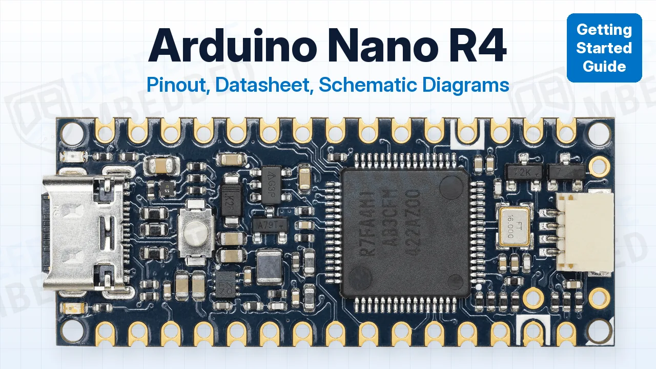
In this guide, you’ll find the Arduino Nano R4 pinout diagram, its datasheet and schematic diagram, and every pin group explained with its default pins and gotchas. Without further ado, let’s get right into it!
The Arduino Nano R4 puts the UNO R4’s Renesas RA4M1, a 48MHz Arm Cortex-M4F with 256KB of flash and 32KB of SRAM, into the classic Nano footprint. It keeps 5v logic on all 20 I/O pins, and adds a USB-C port, a 12-bit DAC, an op-amp, CAN, and a 3.3v Qwiic connector.
Arduino Nano R4 Pinout Diagram
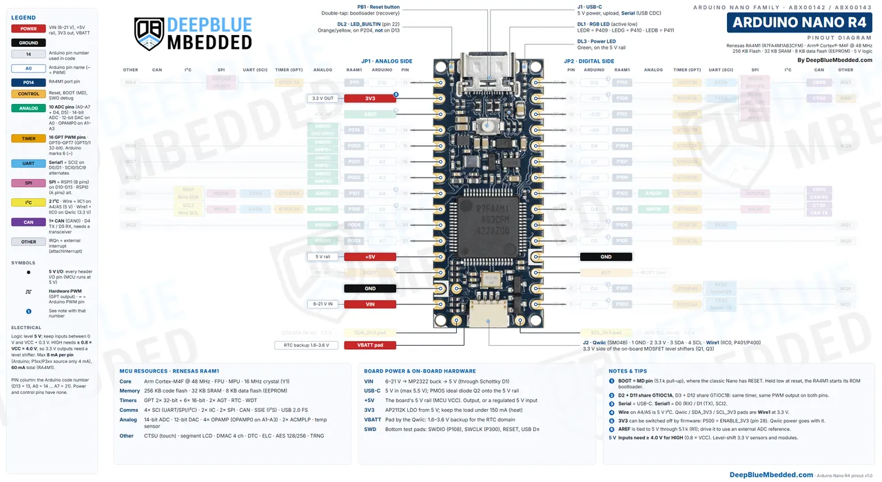
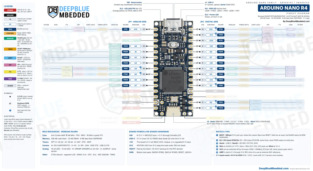
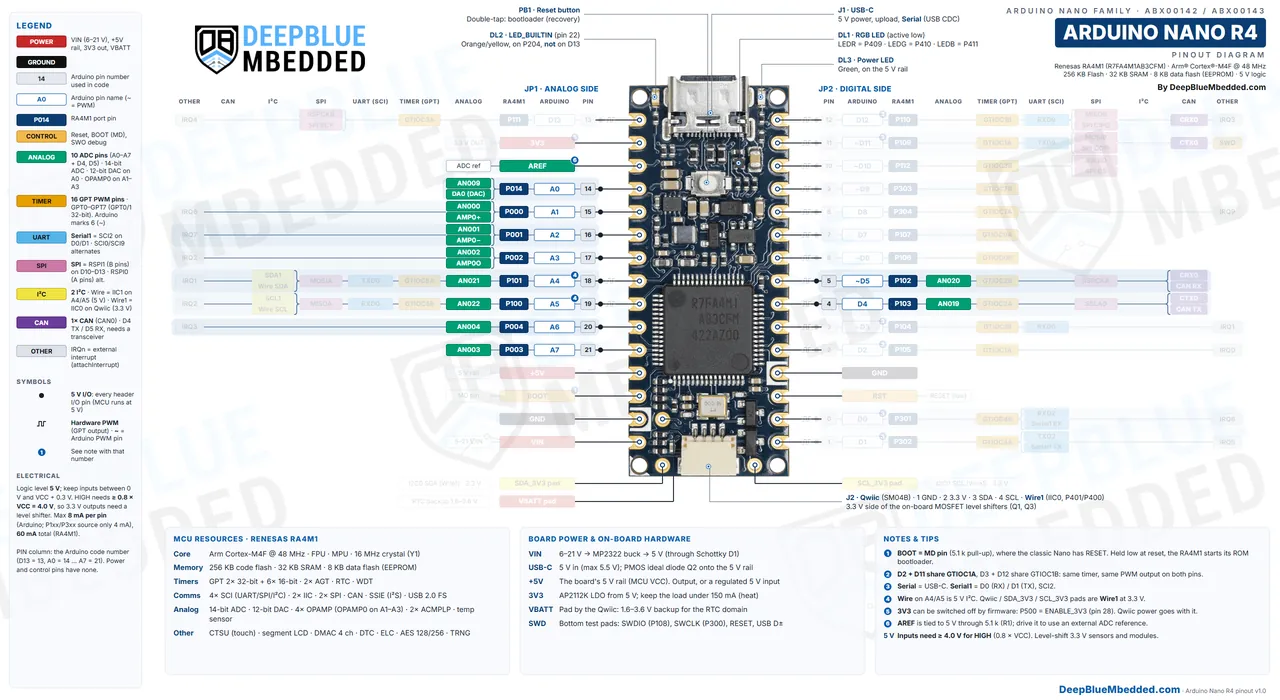
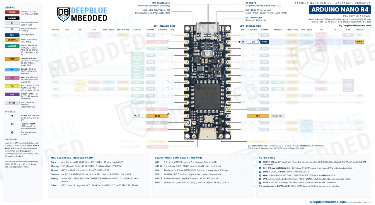
Here is a detailed Arduino Nano R4 Pinout Diagram with colored labels and legends to help you easily identify the functionalities that each pin can perform. It shows both 15-pin headers (JP1, the analog side, and JP2, the digital side), the Qwiic connector and the three extra pads next to it, with the Arduino pin numbers, the RA4M1 port pins, and every pin’s ADC, DAC, op-amp, PWM timer, UART, SPI, I2C and CAN functions.
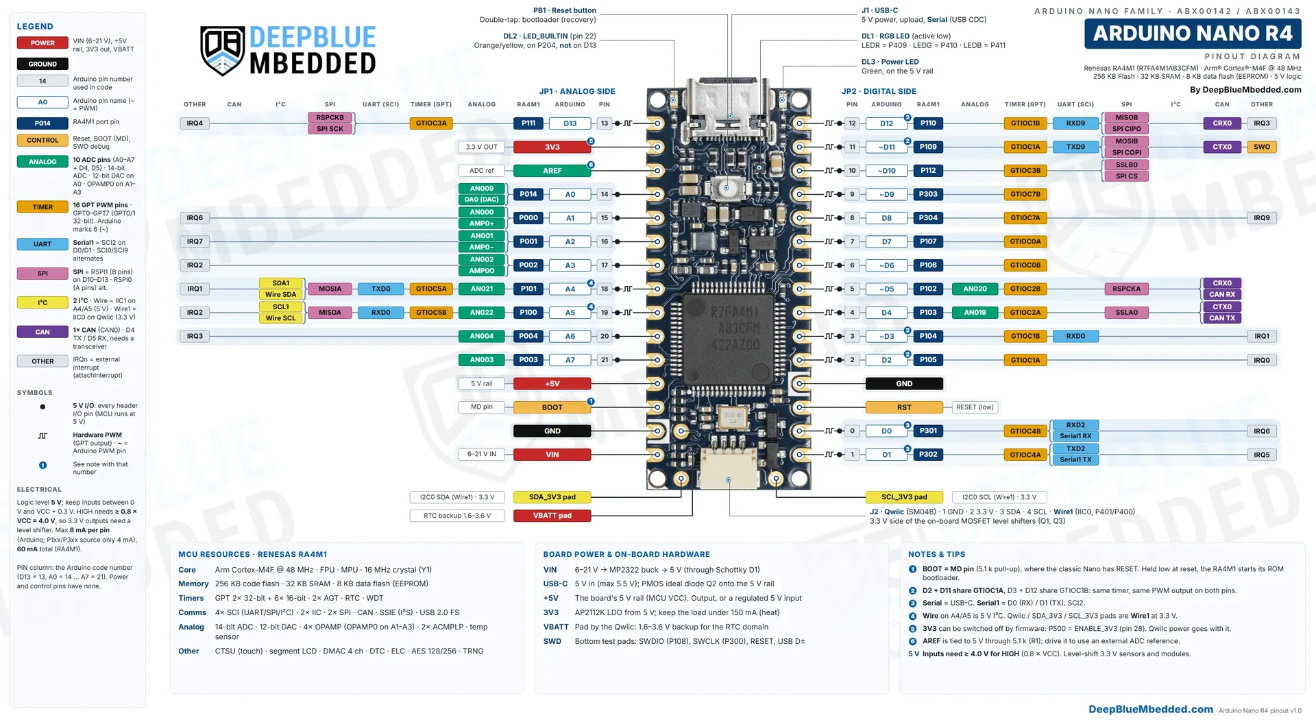
Each row shows the Arduino pin number the core uses (D0–D13 are 0–13, A0–A7 are 14–21), the pin name, the RA4M1 port (P014, P101…), and its functions, color-coded by peripheral. Power and control pins (3V3, AREF, +5V, BOOT, RST, VIN) have no number. The dot symbol means the pin runs at 5v logic, the PWM symbol marks a hardware timer output, and the numbered badges point to the notes at the bottom of the diagram.
With the USB-C connector at the top, JP1 (left) runs from D13 (pin 1) down to VIN (pin 15), and JP2 (right) runs from D1/TX (pin 1, bottom) up to D12 (pin 15, top), as in Arduino’s datasheet and schematic. The rows are 15.24mm (600 mil) apart, like every Nano, and the Qwiic connector sits at the end opposite the USB-C port.
Buy an Arduino Nano R4: If you don’t have one yet, you can get the genuine Arduino board (ABX00143, with headers) from Amazon or AliExpress. It runs the same Arduino core as the UNO R4, so most UNO R4 sketches and libraries work on it right away.
Download Arduino Nano R4 Pinout Diagram (Full Resolution)
The Arduino Nano R4 pinout diagram (JP1 and JP2 headers, Qwiic connector and extra pads) in full resolution (5120×2800 px WebP), in one ZIP file. Print it, zoom in, or keep it next to your bench. Please consider supporting my work if it helped you.
Arduino Nano R4 Datasheet
This development board is built around the Renesas RA4M1 microcontroller (R7FA4M1AB3CFM, LQFP64), the same chip as the UNO R4 Minima and UNO R4 WiFi. So the Arduino Nano R4 datasheet set has two parts: Arduino’s documents for the board and Renesas’s for the chip. Here are the official documents you’ll need, linked to their original sources:
| Document | ID | Revision | What You’ll Use It For | Link |
|---|---|---|---|---|
| Arduino Nano R4 datasheet | ABX00142 / ABX00143 | Rev 4 (20 Oct 2026) | Board specs, power options, current limits, header pin lists | |
| Arduino Nano R4 schematic | ABX00142 | V1.2 (29 May 2025) | The full board circuit (see the next section) | |
| Arduino Nano R4 full pinout | ABX00142 | Nov 2025 | Arduino’s pin map, including the bottom test pads | |
| Arduino Nano R4 user manual | Arduino Docs | Sep 2026 | Core features: RGB LED, DAC, OPAMP, RTC, CAN, Qwiic, HID, bootloader | Web |
| RA4M1 Group datasheet | R01DS0355EJ0110 | Rev.1.10 (Sep 2023) | Pin functions (multiplexing), electrical limits, drive current, input levels | |
| RA4M1 Group User’s Manual: Hardware | R01UH0887EJ0110 | Rev.1.10 (Sep 2023) | Registers and every peripheral (GPT, SCI, IIC, CAN, ADC, DAC, boot modes) |
Which document do I need? The Arduino datasheet for the board’s power limits and header map, the schematic for what’s connected to each pin, the RA4M1 datasheet for pin functions and electrical limits, and the hardware manual when you write register-level code. Arduino keeps all its board files on the Arduino Nano R4 product page, and its Nano R4 user manual has the core-specific examples.
Arduino Nano R4 Schematic
The Arduino Nano R4 schematic is Arduino’s ABX00142 drawing, version V1.2 (29 May 2025), shared by the boards with and without headers. It’s one sheet, so here is the full sheet followed by close-ups of each block; click a page to view it full screen.
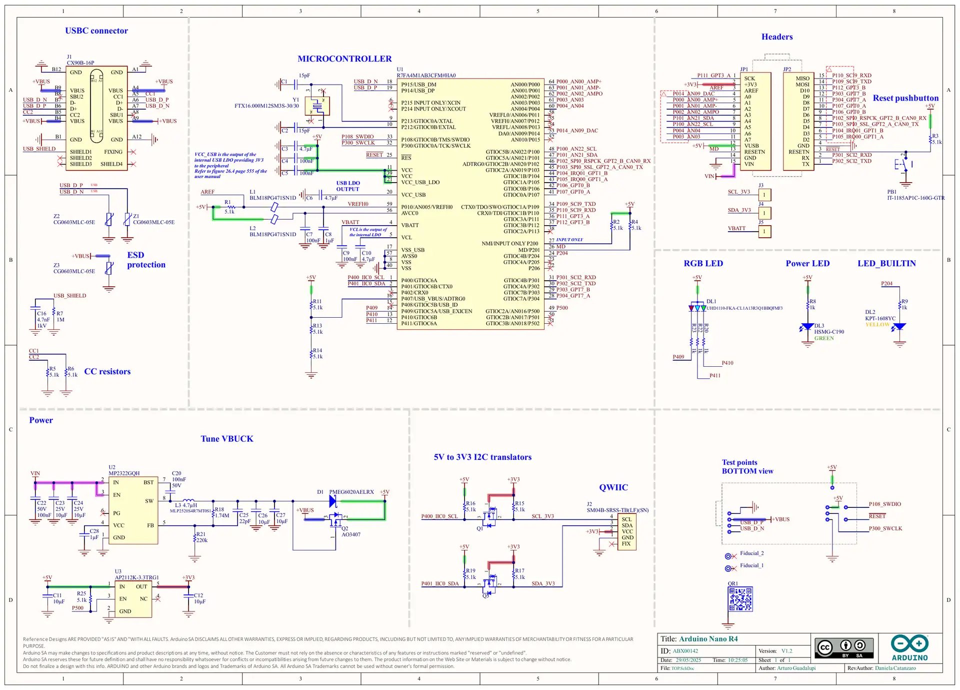
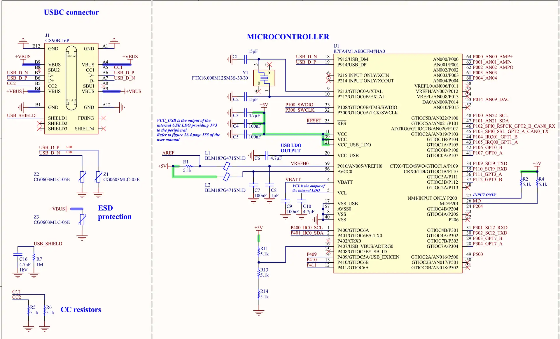
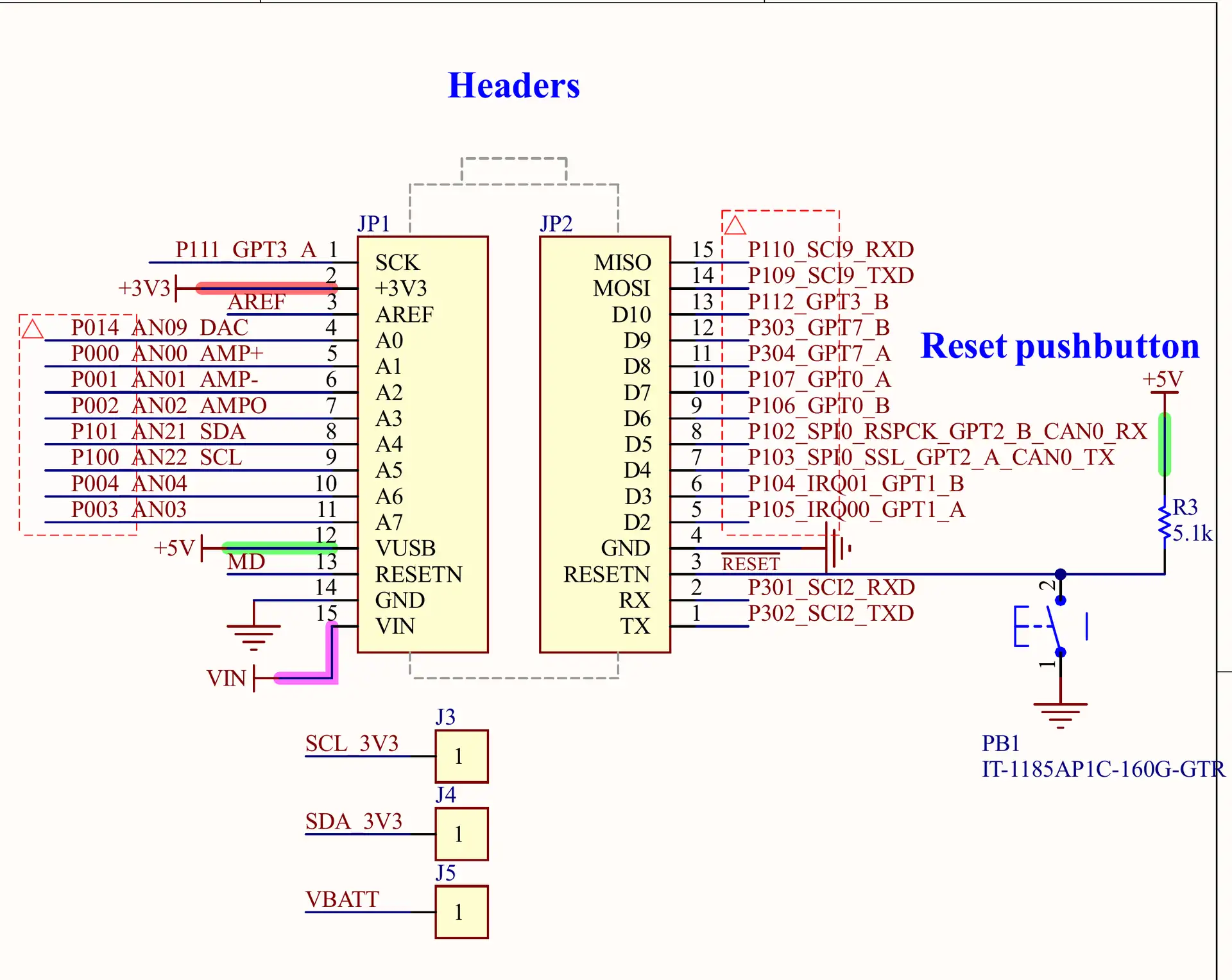
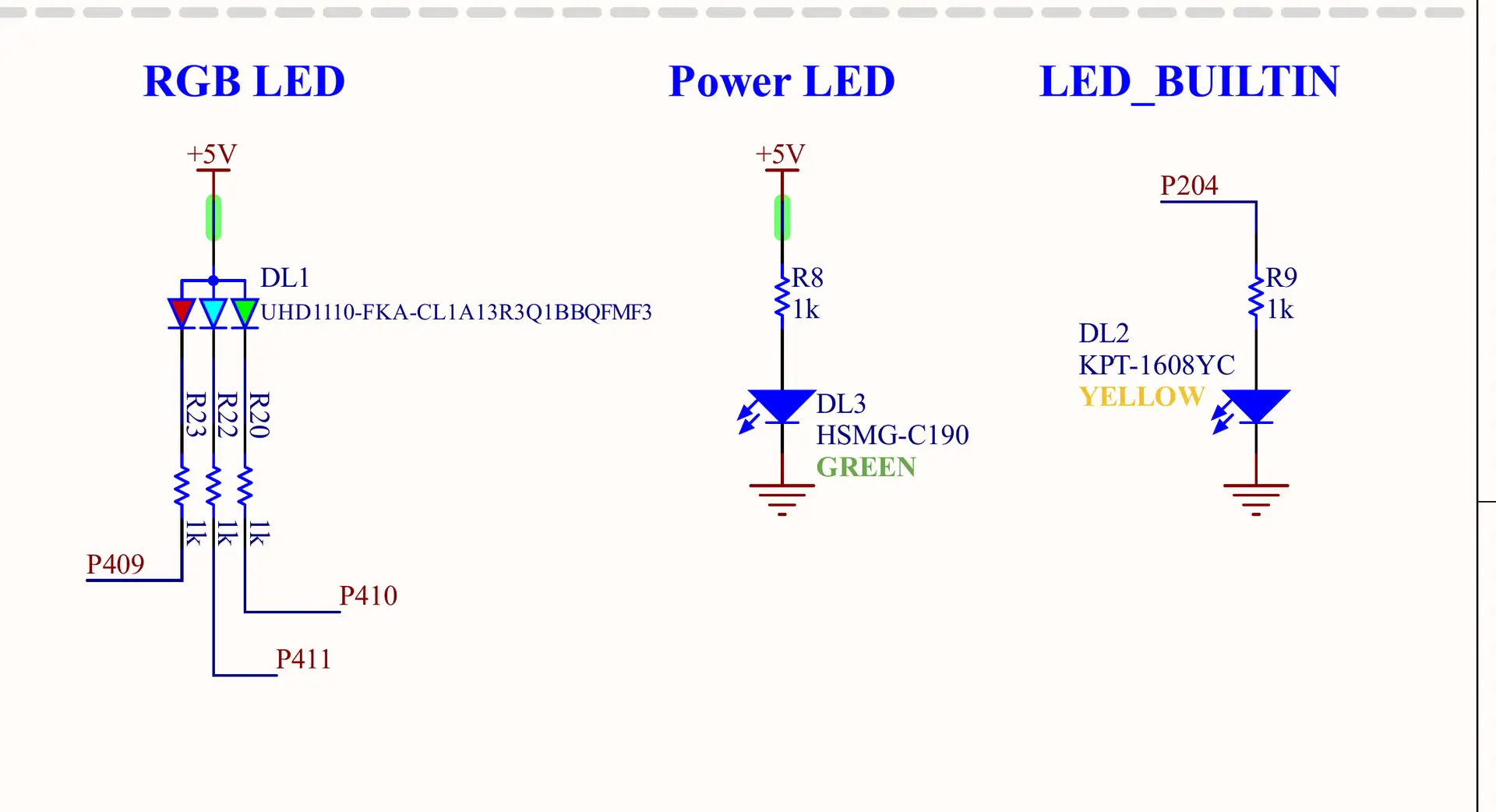
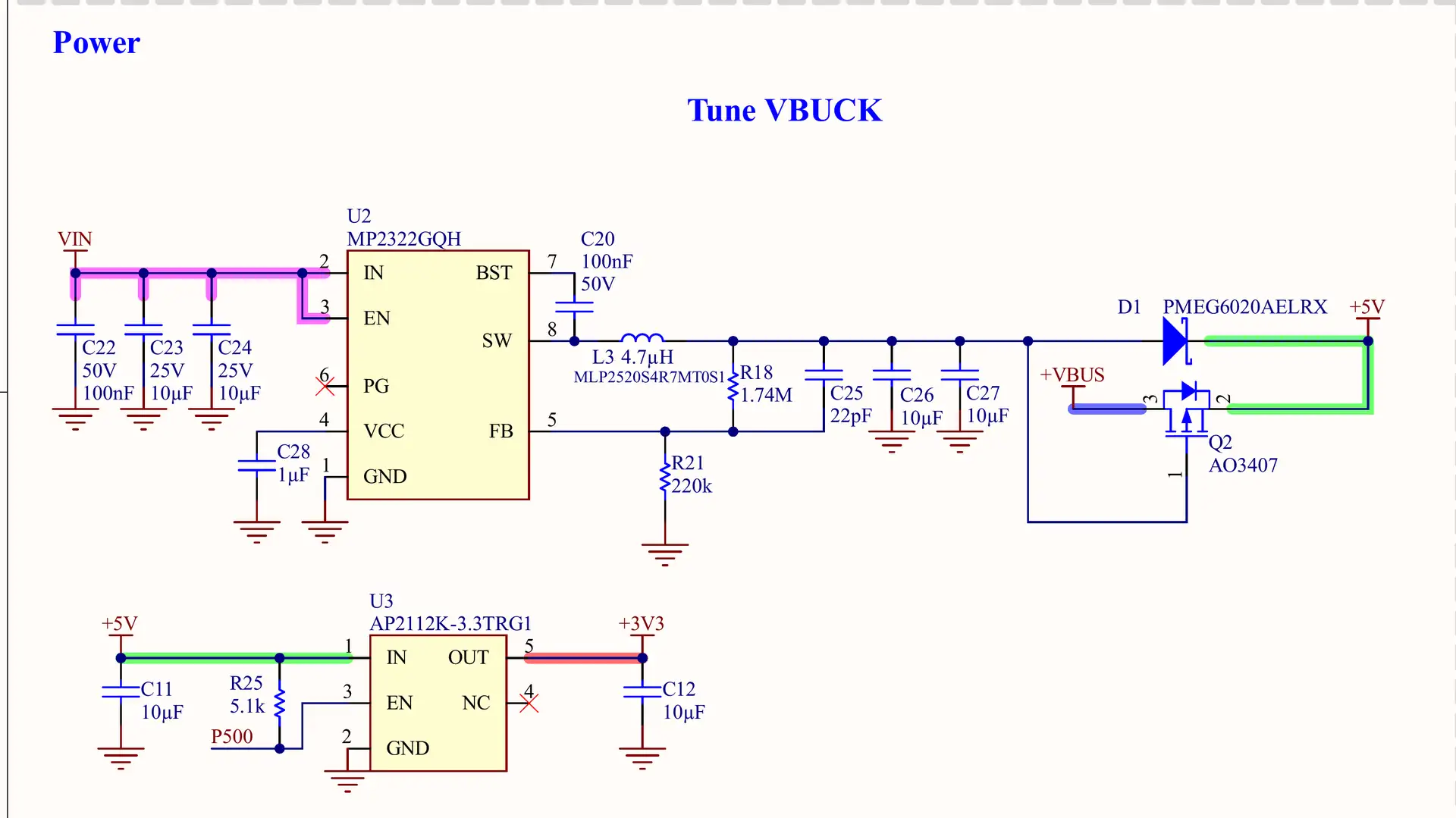
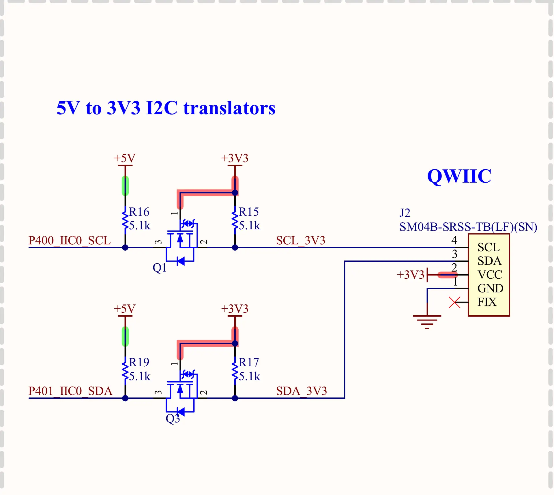
Official source: the Arduino Nano R4 schematic V1.2 (PDF) on Arduino Docs. Here’s what to look at:
- Power path: VIN (6v–21v) feeds the MP2322GQH buck converter (U2), which makes 5v and reaches the +5V rail through the Schottky diode D1 (PMEG6020). USB-C VBUS reaches the same rail through Q2 (AO3407), a P-MOSFET used as an ideal diode. That’s the “power OR” circuit in Arduino’s datasheet.
- 3.3v rail: the AP2112K-3.3 LDO (U3) makes 3.3v from the 5v rail for the 3V3 pin, the Qwiic connector and the 3.3v side of the I2C shifters. Its EN pin is driven by P500 (with a 5.1kΩ pull-up), so a sketch can turn the whole 3.3v rail off.
- RA4M1 (U1): runs from the 5v rail (VCC and AVCC0 = 5v), which is why every header pin is 5v logic. The 16MHz crystal (Y1) sits on P212/P213. XCIN/XCOUT (P214/P215) are not connected: there’s no 32.768kHz crystal. USB D+/D− go straight to the chip’s own USB (P914/P915) through the ESD diodes Z1/Z2.
- AREF: connected to +5V through R1 (5.1kΩ) and to the chip’s VREFH0 through the ferrite bead L1, so the ADC reference is 5v when nothing is connected.
- Headers: JP1 pin 13 is the MD (boot mode) pin with the 5.1kΩ pull-up R4, labelled BOOT on the board; on a classic Nano this position is RESET. RST (JP2-3) has the 5.1kΩ pull-up R3 and the reset button PB1. The schematic names the 5V pin (JP1-12) “VUSB”, but it’s the board’s +5V rail.
- Qwiic (J2): the chip’s second I2C bus, IIC0 on P401 (SDA) and P400 (SCL), goes through two MOSFET level translators (Q1, Q3) with 5.1kΩ pull-ups on both sides. The 3.3v side also comes out on the J3 (SCL_3V3) and J4 (SDA_3V3) pads, next to the J5 VBATT pad.
- LEDs: the common-anode RGB LED (DL1) on P409/P410/P411 through 1kΩ resistors (active LOW), the yellow LED_BUILTIN (DL2) on P204, and the green power LED (DL3) on the 5v rail.
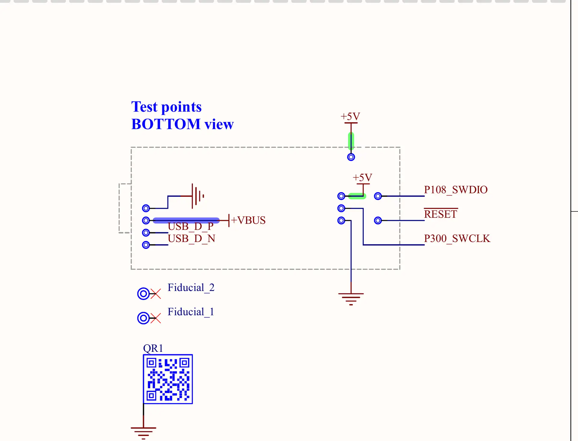
- Test points (bottom): SWDIO (P108), SWCLK (P300), RESET, USB D+/D−, VBUS, +5V and GND, for a debug probe.
Note: The user manual’s digital-pin table lists D0 as P302 (TX) and D1 as P301 (RX), but the schematic, the Arduino core, and the full pinout all say D0 = P301 = RX and D1 = P302 = TX, which is what this article uses. The schematic also labels D11/D12 as SCI9 TXD/RXD, while the core drives them as SPI (RSPI1 MOSIB/MISOB).
Arduino Nano R4 Specs
The Arduino Nano R4 is a Nano-size RA4M1 board from Arduino. Here are its specifications, including the board-level parts that chip-only spec lists usually skip.
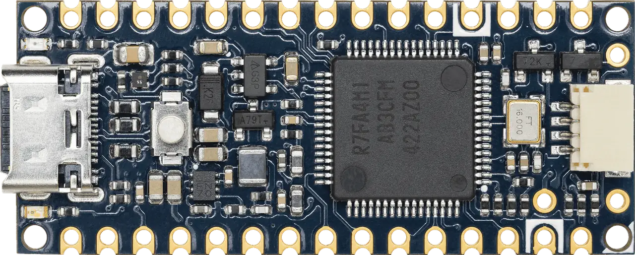
Get an Arduino Nano R4: The genuine Arduino board (ABX00143, with headers) is the one I recommend. Grab it from Amazon or AliExpress.
| Item | Arduino Nano R4 |
|---|---|
| Microcontroller | Renesas RA4M1 (R7FA4M1AB3CFM, LQFP64) |
| CPU | 32-bit Arm Cortex-M4F at 48MHz, with FPU and MPU |
| Memory | 256KB flash, 32KB SRAM, 8KB data flash (used as EEPROM) |
| Logic level | 5v on every header pin; 3.3v only on the Qwiic connector and its two pads |
| I/O pins | 20 on the headers: D0–D13, A0–A7 |
| Analog | 8 ADC inputs (A0–A7, up to 14-bit), 1x 12-bit DAC (A0), 1x op-amp (A1–A3) |
| Board supply | USB-C 5v (4.8v–5.5v, 500mA), or 6v–21v on VIN |
| 5v regulator | MP2322GQH synchronous buck converter (VIN to 5v) |
| 3.3v regulator | AP2112K-3.3 LDO; the board gets very hot above 150mA on the 3V3 pin |
| Pin current | 8mA per pin (Arduino); RA4M1: 60mA total for all outputs |
| Clocks | 16MHz crystal (Y1); no 32.768kHz crystal |
| USB connector | USB-C, wired to the RA4M1’s native USB (upload, Serial, HID keyboard/mouse) |
| Connectors | 2x 15-pin Nano headers, Qwiic (JST SH 4-pin, 3.3v), VBATT/SDA_3V3/SCL_3V3 pads |
| Debug | SWD on the bottom test pads (SWDIO P108, SWCLK P300) |
| User I/O | RGB LED (active LOW), yellow LED_BUILTIN (P204), green power LED, reset button |
| Form factor | Arduino Nano, 18 × 45mm, castellated pads |
| Order codes | ABX00142 (without headers), ABX00143 (with headers) |
| Operating temperature | −40°C to +85°C |
| No | Wi-Fi, Bluetooth, or 32.768kHz RTC crystal |
Arduino Nano R4 Specifications Summary
- The Arduino Nano R4 runs a Renesas RA4M1 (Arm Cortex-M4F) at 48MHz with 256KB flash, 32KB SRAM and 8KB EEPROM (data flash), the same MCU as the UNO R4.
- It has 20 I/O pins on the headers (D0–D13, A0–A7), and they all work at 5v logic: outputs swing to 5v, and a HIGH input needs at least 4.0v.
- It has 8 analog inputs (A0–A7) with a 14-bit ADC (10-bit by default), a 12-bit DAC on A0, and an op-amp on A1 (+), A2 (−), A3 (out).
- analogWrite() gives PWM on 16 pins (D0–D13, A4, A5); Arduino marks 6 of them with “~” (D3, D5, D6, D9, D10, D11).
- Serial is the USB-C port; Serial1 is the hardware UART on D0 (RX) / D1 (TX).
- Wire is on A4 (SDA) / A5 (SCL) at 5v; Wire1 is the Qwiic connector at 3.3v (RA4M1 IIC0).
- SPI is D11 (COPI), D12 (CIPO), D13 (SCK) with D10 as CS.
- The CAN pins are D4 (TX) and D5 (RX); they need an external CAN transceiver.
- 13 pins support attachInterrupt(): D0, D1, D2, D3, D8, D12, D13, A1–A6.
- Power it from USB-C (5v) or VIN (6v–21v); the +5V and 3V3 pins are outputs.
- LED_BUILTIN is on P204 (pin 22), not on D13; the RGB LED is LEDR/ LEDG/ LEDB (active LOW).
- Each pin is rated 8mA by Arduino; keep the total of all outputs under 60mA (Renesas).
Arduino Nano R4 Peripherals: RA4M1 vs On the Headers
The RA4M1 has more peripherals than the Nano headers can expose. This table shows what the chip has and what you can actually reach on the Nano R4.
| Peripheral | RA4M1 | On the Nano R4 |
|---|---|---|
| GPIO | 51 I/O on the LQFP64 | 20 (D0–D13, A0–A7) |
| ADC | 14-bit SAR, up to 25 channels | 8 Arduino inputs (A0–A7); the chip also has AN019/AN020 on D4/D5 |
| DAC | 1x 12-bit (DA0) | A0 |
| Op-amp | 4 (OPAMP0–3) | OPAMP0 complete on A1 (+), A2 (−), A3 (out) |
| PWM timers | 2x 32-bit GPT + 6x 16-bit GPT | 16 GPT outputs: D0–D13, A4, A5 |
| UART (SCI) | 4 (SCI0, SCI1, SCI2, SCI9) | Serial1 = SCI2 on D0/D1 |
| SPI | 2 (RSPI0, RSPI1) | Arduino SPI = RSPI1 on D10–D13 |
| I2C | 2 (IIC0, IIC1) | Wire = IIC1 on A4/A5 (5v); Wire1 = IIC0 on Qwiic (3.3v) |
| CAN | 1 (CAN 2.0B) | D4 (TX), D5 (RX) |
| USB | USB 2.0 Full-Speed | USB-C connector only |
| RTC | Yes (with VBATT domain) | Runs from the internal LOCO oscillator; VBATT pad for backup |
| Touch (CTSU) | Yes | Not supported by the Arduino core on this board |
| Not on the board | – | Wi-Fi, Bluetooth, 32.768kHz crystal |
Arduino Nano R4 Quick Pin Selection Guide
Not sure which pin to use? Here are the Arduino Nano R4 pins I’d pick first for each job, and why.
| Use Case | Recommended Pins | Why |
|---|---|---|
| Serial to the PC | USB-C (Serial) | Native USB CDC; no adapter needed |
| Serial to a module (GPS, GSM…) | D0 (RX), D1 (TX) as Serial1 | The only hardware UART on the headers |
| 5v I2C sensors and displays | A4 (SDA), A5 (SCL) | The Arduino Wire bus, at 5v |
| 3.3v I2C sensors | Qwiic connector (Wire1) | Built-in level shifting and 3.3v power |
| SPI devices | D11 (COPI), D12 (CIPO), D13 (SCK), D10 (CS) | The Arduino SPI pins |
| Analog inputs | A0–A7 (A6, A7 first) | A6/A7 have no other role; A4/A5 are I2C |
| True analog output | A0 (DAC) | 12-bit DAC, a real voltage instead of PWM |
| PWM (LEDs, motors, servos) | D3, D5, D6, D9, D10, D11 | The default “~” pins, each on its own timer output |
| CAN bus | D4 (TX), D5 (RX) | Arduino_CAN library defaults; add a transceiver |
| External interrupt | D2, D8, D13, D1 | Each has its own interrupt channel |
| On-board LEDs | LED_BUILTIN, LEDR / LEDG / LEDB | Pins 22–25; the RGB LED is active LOW |
| Safest general GPIO | D2, D6, D7, D8, D9 | No bus, boot or analog role |
Arduino Nano R4 Pins to Use With Caution
| Pin | Reason | What to Do |
|---|---|---|
| BOOT (JP1-13) | RA4M1 MD pin: LOW at power-up starts the Renesas ROM boot mode | Leave it open; check old Nano shields that use this position as RESET |
| AREF | Tied to 5v through 5.1kΩ on the board | Use a reference source that can drive against 5.1kΩ, or leave it open |
| D0, D1 | Serial1 (UART) | Free them only if you don’t need the hardware UART |
| D2 + D11, D3 + D12 | Same timer output (GTIOC1A, GTIOC1B) | Don’t PWM both pins of a pair with different duty cycles |
| A1, A2, A3 | The op-amp’s pins | Not ADC inputs while OPAMP.begin() is active |
| A0 | The DAC output | Not an ADC input while the DAC is in use |
| A4, A5 | The Wire I2C bus | Don’t use them as analog inputs while I2C runs |
| D11 | SPI COPI and the SWO trace pin | Pick one role |
| All header pins | 5v logic; HIGH needs ≥ 4.0v | Level-shift every 3.3v device (or use Qwiic) |
| 3V3 | LDO gets hot above 150mA; P500 can switch it off | Power bigger 3.3v loads separately |
Arduino Nano R4 Pin Numbering: Arduino Pins vs RA4M1 Ports
In the Arduino IDE, the Arduino Nano R4 uses plain Arduino pin numbers: D0–D13 are 0–13 and A0–A7 are 14–21. The RA4M1 port behind each pin (P301, P105…) only matters when you read the Renesas datasheet or write register-level code. Here is the full map from the core’s NANOR4 variant:
| Pin | Arduino # | RA4M1 Port | Pin | Arduino # | RA4M1 Port |
|---|---|---|---|---|---|
| D0 (RX) | 0 | P301 | A0 (DAC) | 14 | P014 |
| D1 (TX) | 1 | P302 | A1 | 15 | P000 |
| D2 | 2 | P105 | A2 | 16 | P001 |
| D3~ | 3 | P104 | A3 | 17 | P002 |
| D4 (CAN TX) | 4 | P103 | A4 (SDA) | 18 | P101 |
| D5~ (CAN RX) | 5 | P102 | A5 (SCL) | 19 | P100 |
| D6~ | 6 | P106 | A6 | 20 | P004 |
| D7 | 7 | P107 | A7 | 21 | P003 |
| D8 | 8 | P304 | LED_BUILTIN | 22 | P204 |
| D9~ | 9 | P303 | LEDR | 23 | P409 |
| D10~ (CS) | 10 | P112 | LEDG | 24 | P410 |
| D11~ (COPI) | 11 | P109 | LEDB | 25 | P411 |
| D12 (CIPO) | 12 | P110 | Qwiic SCL / SDA | 26 / 27 | P400 / P401 |
| D13 (SCK) | 13 | P111 | ENABLE_3V3 | 28 | P500 |
Arduino Nano R4 Pins Functions
The 30 header pins of the Arduino Nano R4 are divided into the following groups based on the hardware functionality they’re used for. Most I/O pins belong to several groups at once.
- Power Pins: VIN, +5V, 3V3, 2x GND, plus the VBATT pad
- 20x Digital GPIO Pins
- 13x Interrupt Pins
- 8x ADC Analog Input Pins
- 1x DAC Pin & 1x Op-Amp
- 16x PWM Pins (6 marked “~”)
- 1x UART Port (+ USB Serial)
- 2x I2C Buses (A4/A5 and Qwiic)
- 1x SPI Port
- 1x CAN Bus
- 1x Native USB Port (USB-C)
- BOOT, Reset & Debug Pins
We’ll discuss each pin group in the following sections one by one in more detail.
Arduino Nano R4 Power Pins
The Arduino Nano R4 is powered from the USB-C port (5v) or from 6v–21v on VIN. VIN goes through the MP2322GQH buck converter to the 5v rail that runs the RA4M1, and an AP2112K LDO makes 3.3v for the 3V3 pin and the Qwiic connector. The power pins are highlighted in red in the pinout diagram.
| Pin | Header Pin | Range | Notes |
|---|---|---|---|
| VIN | JP1-15 | 6v–21v in | Into the MP2322 buck converter, then the 5v rail through Schottky diode D1 |
| +5V | JP1-12 | 5v | The board’s main 5v rail (MCU supply); output on USB or VIN power |
| 3V3 | JP1-2 | 3.3v out | AP2112K LDO; above 150mA the board gets very hot |
| GND | JP1-14, JP2-4 | 0v | All grounds are common |
| VBATT (pad J5) | Next to the Qwiic connector | 1.6v–3.6v in | Backup supply for the RTC domain; switches in below about 2.09v on VCC |
USB-C must stay within 4.8v–5.5v (500mA max, the USB 2.0 limit), and VIN within 6v–21v. When both are connected, the board’s power-OR circuit (D1 + Q2) picks the supply automatically, so you can leave the USB cable in while the board runs from VIN. Arduino’s user manual also allows feeding a regulated 5v into the +5V pin, as long as you’re careful never to exceed 5.5v.
Note: The 3.3v rail can be switched off by software: the LDO’s enable pin is P500, which the core calls ENABLE_3V3 (pin 28). pinMode(ENABLE_3V3, OUTPUT); digitalWrite(ENABLE_3V3, LOW); turns off the 3V3 pin and the Qwiic power together, which is handy for low-power projects, and puzzling if a sketch does it by accident.
Arduino Nano R4 GPIO Pins
The Arduino Nano R4 has 20 GPIO pins on its headers: D0–D13 and A0–A7 (digital pins 14–21). All of them work at 5v logic, just like a classic Nano or UNO, so 5v sensors, modules and shields connect directly.
Each pin can be INPUT, INPUT_PULLUP or OUTPUT. Here are the electrical limits from the Arduino and Renesas datasheets:
- Logic level 5v; never apply more than 5.5v to any pin.
- A HIGH input needs at least 4.0v (0.8 × VCC, RA4M1 datasheet), so a 3.3v signal is not a guaranteed HIGH.
- Arduino rates each pin at 8mA. The RA4M1 datasheet is stricter for the P1xx/P3xx ports (most D pins): 4mA source and 8mA sink at the default drive, and 60mA total for all outputs together (Arduino’s user manual says 200mA total, which the chip doesn’t back up).
- A6 and A7 are normal digital pins too (20 and 21), even though the user manual calls them “analog input only”.
Note: Because the Arduino Nano R4 is a 5v board, a 3.3v sensor on the headers gets 5v on its inputs and may not read as HIGH on the Nano R4. Use a level shifter for 3.3v devices, or plug I2C ones into the Qwiic connector, which has its own shifters.
Learn more in our Arduino digitalWrite() GPIO Tutorial.
Also Read
Arduino Nano R4 Interrupt Pins
The Arduino Nano R4 has 13 interrupt pins: D0, D1, D2, D3, D8, D12, D13 and A1–A6. attachInterrupt(digitalPinToInterrupt(D2), isr, FALLING) works on any of them, with RISING, FALLING, CHANGE and LOW triggers. D4–D7, D9–D11, A0 and A7 have no external interrupt.
| Pin | IRQ Channel | Shared With | Pin | IRQ Channel | Shared With |
|---|---|---|---|---|---|
| D0 | IRQ6 | A1 | A1 | IRQ6 | D0 |
| D1 | IRQ5 | – | A2 | IRQ7 | – |
| D2 | IRQ0 | – | A3 | IRQ2 | A5 |
| D3 | IRQ1 | A4 | A4 | IRQ1 | D3 |
| D8 | IRQ9 | – | A5 | IRQ2 | A3 |
| D12 | IRQ3 | A6 | A6 | IRQ3 | D12 |
| D13 | IRQ4 | – |
Two pins on the same IRQ channel can’t both be interrupts at the same time: pick D3 or A4, D0 or A1, and so on. And on the R4 core, call pinMode() before attachInterrupt(): users report that an interrupt on D2 never fires without it (Arduino Forum).
|
1 2 3 4 5 6 7 8 9 10 11 12 |
volatile bool pressed = false; void onPress() { pressed = true; } void setup() { Serial.begin(115200); pinMode(D2, INPUT_PULLUP); // button from D2 to GND, pinMode first! attachInterrupt(digitalPinToInterrupt(D2), onPress, FALLING); } void loop() { if (pressed) { pressed = false; Serial.println("Button pressed"); } } |
Learn more in our Arduino External Interrupts Tutorial.
Also Read
Arduino Nano R4 ADC Pins
The Arduino Nano R4 has 8 ADC pins, A0–A7, on the RA4M1’s 14-bit ADC. analogRead() returns 10-bit values (0–1023) by default, and analogReadResolution(12) or (14) gives 0–4095 or 0–16383. The input range is 0v to 5v. The ADC pins are highlighted in green in the pinout diagram.
| Pin | RA4M1 Port | ADC Channel | Also |
|---|---|---|---|
| A0 | P014 | AN009 | DAC output |
| A1 | P000 | AN000 | Op-amp + input |
| A2 | P001 | AN001 | Op-amp − input |
| A3 | P002 | AN002 | Op-amp output |
| A4 | P101 | AN021 | I2C SDA (Wire) |
| A5 | P100 | AN022 | I2C SCL (Wire) |
| A6 | P004 | AN004 | – |
| A7 | P003 | AN003 | – |
The default reference is the 5v rail, through the AREF pin’s 5.1kΩ resistor. analogReference(AR_INTERNAL) switches to the internal reference, about 1.43v in the core (Arduino’s manual rounds it to 1.5v), for small signals. Let’s say you read a 0–1v sensor: with the 5v reference and 14-bit resolution you get about 3,277 steps across its range; with the internal reference you get more than 11,000.
Note: The RA4M1 also has ADC channels on D4 (AN019) and D5 (AN020), and the pinout diagram shows them. But in the Arduino core, analogRead(D4) reads A4: analogRead() treats pin numbers below 14 as A0–A7 (0 = A0), like the classic Nano. So stay with A0–A7 for analog inputs.
There are so many sensors that we can read with the ADC pins, which include: potentiometers, LDRs, analog temperature sensors (LM35, TMP36, NTC thermistors), soil moisture sensors, joysticks, current sensors (ACS712), and much more.
|
1 2 3 4 5 6 7 8 9 10 11 |
void setup() { Serial.begin(115200); analogReadResolution(14); // 0..16383 } void loop() { int raw = analogRead(A6); float volts = raw * 5.0 / 16383.0; // default 5v reference Serial.println(volts, 3); delay(500); } |
Learn more in our Arduino ADC analogRead() Tutorial.
Also Read
Arduino Nano R4 DAC and Op-Amp Pins
The Arduino Nano R4 has a 12-bit DAC on A0 and a built-in op-amp on A1 (+), A2 (−) and A3 (output). Neither exists on the classic Nano or the Nano ESP32.
| Function | Pin | How to Use It |
|---|---|---|
| DAC output (12-bit) | A0 (P014, DA0) | analogWriteResolution(12); analogWrite(DAC, 2048); gives about 2.5v |
| Op-amp + input | A1 (P000) | #include <OPAMP.h>, then OPAMP.begin(OPAMP_SPEED_HIGHSPEED); |
| Op-amp − input | A2 (P001) | Wire the feedback network here |
| Op-amp output | A3 (P002) | The amplified signal, from 0.1v to VCC − 0.1v |
The DAC gives a real analog voltage (0v to the 5v reference), not a PWM square wave, so you can make audio tones, sine waves, or a programmable reference without a filter. The op-amp is a full amplifier: wire A3 to A2 for a voltage follower (buffer), or add two resistors for a non-inverting amplifier (two 10kΩ resistors give a gain of 2). Its output swings from 0.1v to about 4.9v (VCC − 0.1v).
Note: While the DAC runs, A0 isn’t an ADC input, and while OPAMP.begin() is active, A1–A3 aren’t ADC inputs either. Plan your analog inputs on A4–A7 (A6 and A7 if you also use I2C).
Arduino Nano R4 PWM Pins
The Arduino Nano R4 can output PWM on 16 pins: D0–D13, A4 and A5, all driven by the RA4M1’s GPT timers. Arduino marks only 6 of them with “~” (D3, D5, D6, D9, D10, D11), the UNO-style default set, but the core’s analogWrite() sets up a timer for any pin that has a GPT output. The PWM pins are highlighted in orange in the pinout diagram.
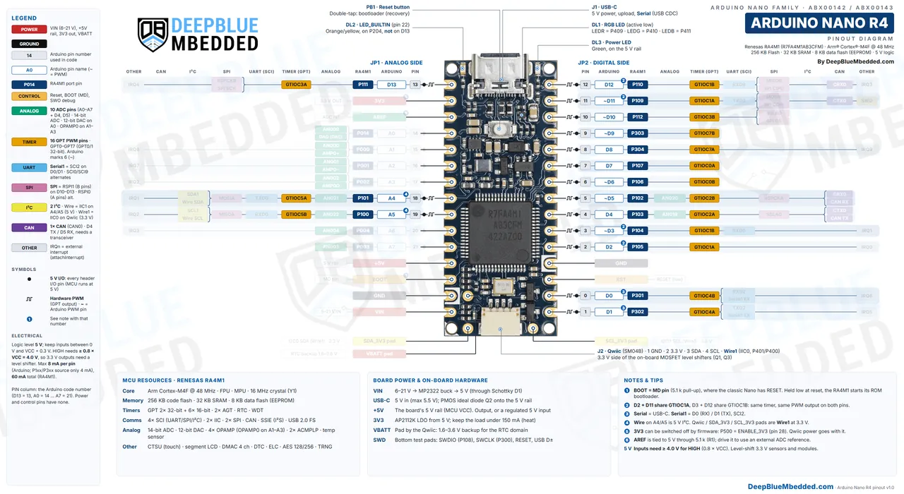
Arduino Nano R4 Default PWM Pins: D3, D5, D6, D9, D10, and D11 (8-bit by default, up to 16-bit with analogWriteResolution(16)).
| GPT Timer | Output A | Output B |
|---|---|---|
| GPT0 (32-bit) | D7 | D6~ |
| GPT1 (32-bit) | D2, D11~ | D3~, D12 |
| GPT2 | D4 | D5~ |
| GPT3 | D13 | D10~ |
| GPT4 | D1 | D0 |
| GPT5 | A4 | A5 |
| GPT7 | D8 | D9~ |
Pins on the same GPT timer share one PWM frequency, and D2/D11 and D3/D12 are even the same output signal (GTIOC1A and GTIOC1B), so they always carry the same duty cycle. That’s why Arduino’s manual notes that D3 and D11 share GPT1. In practice: use the six “~” pins first, and add other pins from different timers when you need more.
Note: The on-board LEDs are PWM-capable too: analogWrite(LED_BUILTIN, 64) dims the yellow LED, and the RGB LED pins (LEDR, LEDG, LEDB) can mix colors. Remember the RGB LED is active LOW, so 255 is off.
There are so many things that we can control with PWM, which include: LED dimming, RGB LEDs, DC motor speed (with a driver), servo motors, buzzers, ESCs for brushless motors, and much more.
Learn more in our Arduino PWM analogWrite() Tutorial.
Also Read
Arduino Nano R4 UART Pins
The Arduino Nano R4 has 1 hardware UART on its headers: Serial1 on D0 (RX) and D1 (TX) (RA4M1 SCI2). Serial is the native USB-C port, which talks to the Serial Monitor. The UART pins are highlighted in blue in the pinout diagram.
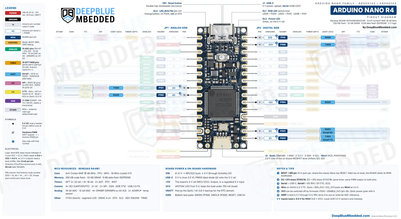
Arduino Nano R4 Default UART Pins: D0 (RX) and D1 (TX) for Serial1.
| Port | Arduino Object | RX Pin | TX Pin | Note |
|---|---|---|---|---|
| USB CDC | Serial | USB-C | USB-C | Serial Monitor over the USB cable |
| SCI2 | Serial1 | D0 (P301) | D1 (P302) | 5v logic, 300 baud to 2Mbaud |
Unlike the classic Nano, D0/D1 aren’t shared with the USB port, so you can talk to a GPS or GSM module on Serial1 and print debug messages to the PC on Serial at the same time.
|
1 2 3 4 5 6 7 8 9 |
void setup() { Serial.begin(115200); // USB-C to the PC Serial1.begin(9600); // D0 = RX, D1 = TX } void loop() { while (Serial1.available()) Serial.write(Serial1.read()); // module -> PC while (Serial.available()) Serial1.write(Serial.read()); // PC -> module } |
Note: Old sketches written for the classic Nano use Serial for D0/D1. On the Nano R4, change them to Serial1, or the module gets nothing. And a 3.3v module’s TX may not reach the 4.0v HIGH level on D0, so add a level shifter.
There are so many modules that we can interface with the UART pins, which include: GPS modules, GSM/LTE modules, fingerprint sensors, RS485 transceivers, DFPlayer Mini, Bluetooth modules (HC-05), other microcontrollers, and much more.
Learn more in our Arduino UART Serial Communication Tutorial.
Arduino Nano R4 I2C Pins
The Arduino Nano R4 has 2 I2C buses. Wire is on A4 (SDA) and A5 (SCL) at 5v (RA4M1 IIC1), the same place as on every Nano. Wire1 is the Qwiic connector at 3.3v (RA4M1 IIC0 on P401/P400), with on-board MOSFET level translators. The I2C pins are highlighted in yellow in the pinout diagram.
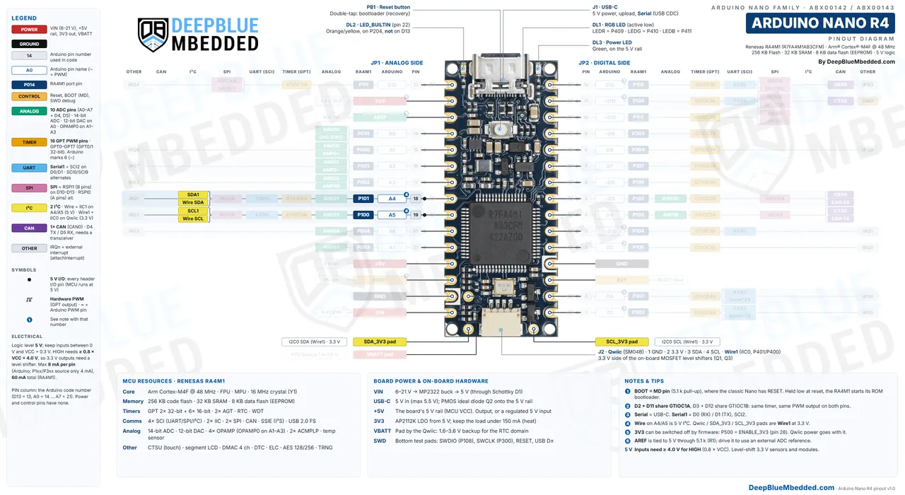
Arduino Nano R4 Default I2C Pins: A4 (SDA) and A5 (SCL) for Wire; the Qwiic connector for Wire1.
| I2C Bus | Arduino Object | SDA | SCL | Level | Note |
|---|---|---|---|---|---|
| IIC1 | Wire | A4 (P101) | A5 (P100) | 5v | Classic Nano position; no pull-ups on the board |
| IIC0 | Wire1 | Qwiic pin 3 / pad J4 (P401) | Qwiic pin 4 / pad J3 (P400) | 3.3v | 5.1kΩ pull-ups on both sides of the shifters |
The Qwiic connector is a JST SH 4-pin (SM04B-SRSS-TB) in the standard order: GND, 3.3v, SDA, SCL. It works with SparkFun Qwiic, Adafruit STEMMA QT and Arduino Modulino boards. If you’d rather solder, the same 3.3v bus comes out on the SDA_3V3 and SCL_3V3 pads next to it.
|
1 2 3 4 5 6 7 8 9 10 11 12 13 |
#include <Wire.h> // gives both Wire and Wire1 (there is no Wire1.h) void setup() { Serial.begin(115200); Wire.begin(); // A4/A5, 5v devices Wire1.begin(); // Qwiic, 3.3v devices for (byte a = 1; a < 127; a++) { Wire1.beginTransmission(a); if (Wire1.endTransmission() == 0) { Serial.print("Qwiic device at 0x"); Serial.println(a, HEX); } } } void loop() {} |
Note: Most Qwiic library examples call Wire; on the Nano R4 the Qwiic port is Wire1, so pass it to the library (for example sensor.begin(Wire1)). And A4/A5 have no pull-ups on the board, so add 4.7kΩ pull-ups to 5v unless your module already has them.
There are so many modules and sensors that we can interface with the I2C bus, which include: OLED displays (SSD1306), I2C LCDs, RTC modules (DS3231), IMUs (MPU6050), BME280 sensors, port expanders, Qwiic and Modulino nodes, and much more.
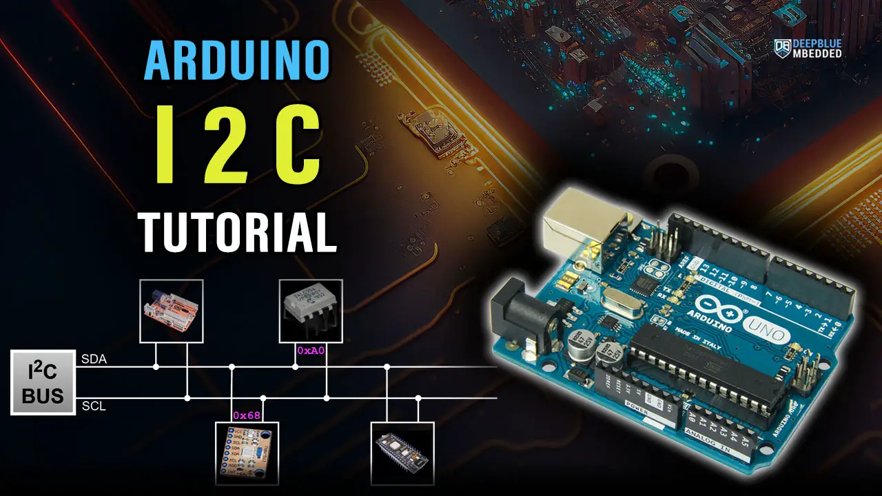
Learn more in our Arduino I2C Tutorial.
Also Read
Arduino Nano R4 SPI Pins
The Arduino Nano R4 has 1 SPI port in the Arduino core (RA4M1 RSPI1). The default SPI pins are D11 (COPI), D12 (CIPO) and D13 (SCK), with D10 as CS, the same as the classic Nano. The SPI pins are highlighted in pink in the pinout diagram.
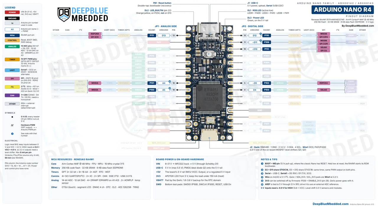
Arduino Nano R4 Default SPI Pins: D11 (COPI/MOSI), D12 (CIPO/MISO), D13 (SCK), and D10 (CS).
| Signal | Pin | RA4M1 Port | Note |
|---|---|---|---|
| SCK | D13 | P111 (RSPCKB) | Not loaded by an LED on this board |
| CIPO (MISO) | D12 | P110 (MISOB) | |
| COPI (MOSI) | D11 | P109 (MOSIB) | Also SWO |
| CS (SS) | D10 | P112 (SSLB0) | Any GPIO can be an extra CS |
The chip’s second SPI (RSPI0) is also on the headers (SCK on D5, MISO on A5, MOSI on A4, SS on D4), but the Arduino core doesn’t create an object for it, and those pins are your I2C and CAN pins anyway.
There are so many modules that we can interface with the SPI bus, which include: TFT displays (ILI9341, ST7789), SD card modules, LoRa radios (SX1276), nRF24L01 radios, MAX7219 LED drivers, W5500 Ethernet modules, and much more.
Arduino Nano R4 CAN Pins
The Arduino Nano R4 has 1 CAN 2.0B controller. Its default pins are D4 (CAN TX) and D5 (CAN RX), up to 1Mbps, with standard (11-bit) and extended (29-bit) IDs. It needs an external CAN transceiver, since the board has none. The CAN pins are highlighted in purple in the pinout diagram.
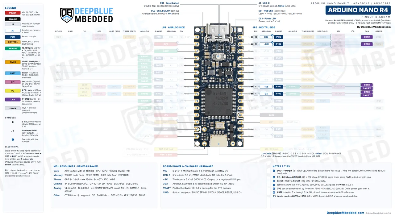
Arduino Nano R4 Default CAN Pins: D4 (TX) and D5 (RX), used by the Arduino_CAN library that comes with the core.
Because the board is 5v, you can use a 5v transceiver like the MCP2551 or TJA1050 directly. A 3.3v transceiver like the SN65HVD230 outputs only 3.3v on RXD, below the 4.0v HIGH level of D5, so it isn’t a safe match. Wire the transceiver’s TXD to D4 and RXD to D5, and terminate the bus with 120Ω at both ends.
|
1 2 3 4 5 6 7 8 9 10 11 12 |
#include <Arduino_CAN.h> void setup() { Serial.begin(115200); if (!CAN.begin(CanBitRate::BR_500k)) { Serial.println("CAN init failed"); while (1); } } void loop() { uint8_t data[] = {0xCA, 0xFE}; CAN.write(CanMsg(CanStandardId(0x20), sizeof(data), data)); delay(1000); } |
Arduino Nano R4 USB Pins
The Arduino Nano R4’s USB-C connector is wired straight to the RA4M1’s native USB (P914 D−, P915 D+). There’s no USB-UART chip: the same port does the uploads, the Serial port, and USB device modes like HID keyboard and mouse ( Keyboard.h, Mouse.h).
| Signal | RA4M1 Pin | On This Board |
|---|---|---|
| USB D− | P914 | USB-C connector (and a bottom test pad) |
| USB D+ | P915 | USB-C connector (and a bottom test pad) |
| VBUS | – | Into the 5v rail through Q2 |
Because USB is handled by the RA4M1 itself, a sketch that crashes early can make the port disappear. That’s what the double-tap reset in the next section is for.
Arduino Nano R4 BOOT, Reset and Debug Pins
The Arduino Nano R4 has a BOOT pin (JP1-13) and a RST pin (JP2-3). BOOT is the RA4M1’s MD pin: if it’s LOW when the chip comes out of reset, the RA4M1 starts its Renesas ROM boot mode instead of your sketch. RST resets the board when pulled LOW, like the reset button.
| Pin | RA4M1 | Role | On the Board |
|---|---|---|---|
| BOOT (JP1-13) | MD (P201) | LOW at reset = ROM (SCI/USB) boot mode | 5.1kΩ pull-up to 5v |
| RST (JP2-3) | RES | Reset, active LOW | 5.1kΩ pull-up, reset button PB1 |
| SWDIO / SWCLK | P108 / P300 | SWD debug | Bottom test pads only |
| D11 | P109 | SWO trace output (alternate) | Shared with SPI COPI |
Arduino Nano R4 Bootloader Recovery Steps
If your Arduino Nano R4 isn’t detected anymore (no port after an upload), try these steps, in this order:
- Double-tap reset: press the reset button twice quickly. The board stays in the Arduino bootloader (the yellow LED fades), so you can upload a working sketch.
- ROM boot mode (if the bootloader is damaged): connect BOOT to GND, then plug in the USB cable. Flash dfu_nano.hex (in the core’s bootloaders/NANOR4 folder) with the Renesas Flash Programmer, remove the wire, and reset. Arduino walks through it in its Nano R4 bootloader recovery tutorial.
Note: On a classic Nano, JP1-13 is a second RESET pin. A Nano shield or expansion board that connects that position to a reset circuit can hold BOOT LOW at power-up, and the Nano R4 then sits in ROM boot mode instead of running your sketch. Check what your shield does with that pin before plugging the board in.
Arduino Nano R4 On-Board Features
Besides the headers, the Arduino Nano R4 has 3 LEDs (one of them RGB), a reset button, a crystal, the Qwiic connector, and a real-time clock. Here’s what each one does.
| Part | Pin / Connection | What It Does |
|---|---|---|
| RGB LED (DL1) | LEDR P409 (23), LEDG P410 (24), LEDB P411 (25) | Common anode, active LOW: digitalWrite(LEDR, LOW) turns red on |
| Yellow LED (DL2) | P204 (22) | LED_BUILTIN, active HIGH; fades while the bootloader waits |
| Green power LED (DL3) | 5v rail | On whenever 5v is present |
| Reset button (PB1) | RES to GND | One press resets; a double-tap enters the bootloader |
| 16MHz crystal (Y1) | P212 / P213 | Accurate main clock (for USB and timing) |
| Qwiic connector (J2) | IIC0 (P401/P400) via level shifters | 3.3v I2C bus, Wire1 |
| RTC | Internal, clocked by LOCO | Date and time with RTC.h; VBATT pad for backup |
A note on the RTC: the board has no 32.768kHz crystal, so the core’s RTC.h runs the RTC from the RA4M1’s internal LOCO oscillator. Renesas specifies LOCO at 27.85kHz–37.68kHz (32.768kHz typical, about ±15%), so the clock can drift a lot over a day. It’s fine for timestamps that get corrected from the PC or a network, but for an accurate clock, add a DS3231 module on the Qwiic or A4/A5 bus.
Here’s a first test that cycles the RGB LED and blinks the yellow LED. Note the inverted logic of the RGB LED:
|
1 2 3 4 5 6 7 8 9 10 11 12 13 14 15 |
void setup() { pinMode(LEDR, OUTPUT); pinMode(LEDG, OUTPUT); pinMode(LEDB, OUTPUT); pinMode(LED_BUILTIN, OUTPUT); } void show(bool r, bool g, bool b) { // the RGB LED is active LOW digitalWrite(LEDR, !r); digitalWrite(LEDG, !g); digitalWrite(LEDB, !b); } void loop() { show(1, 0, 0); delay(400); show(0, 1, 0); delay(400); show(0, 0, 1); delay(400); digitalWrite(LED_BUILTIN, !digitalRead(LED_BUILTIN)); } |
Getting Started With Arduino Nano R4
You can program the Arduino Nano R4 with the Arduino IDE (or Arduino Cloud) and PlatformIO, all over the USB-C cable. No external programmer is needed.
- Arduino IDE 2: in the Boards Manager, install “Arduino UNO R4 Boards” (the same core as the UNO R4 Minima and WiFi), then select Arduino Nano R4. Uploads go over USB with no button to press.
- Libraries: the core includes OPAMP.h, RTC.h, Arduino_CAN.h, EEPROM.h, Keyboard.h/ Mouse.h (HID), and the usual Wire and SPI.
- Most UNO R4 Minima code runs as is. Just check the pins that differ: LED_BUILTIN isn’t on D13, and the Qwiic port is Wire1.
| Arduino Name | Pin | Default |
|---|---|---|
Serial | USB-C | USB CDC to the Serial Monitor |
Serial1 | D0 (RX), D1 (TX) | SCI2 |
Wire | A4 (SDA), A5 (SCL) | IIC1, 5v |
Wire1 | Qwiic connector | IIC0, 3.3v |
SPI | D11 / D12 / D13, SS = D10 | RSPI1 |
CAN | D4 (TX), D5 (RX) | CAN0 |
LED_BUILTIN | 22 (P204) | Yellow LED, active HIGH |
LEDR / LEDG / LEDB | 23 / 24 / 25 | RGB LED, active LOW |
DAC | A0 | 12-bit DAC |
Arduino Nano R4 Common Problems & Fixes
Why doesn’t LED_BUILTIN blink on D13? Because it isn’t on D13. The yellow LED is on P204 (pin 22). Use LED_BUILTIN in your code, and D13 stays free for SPI SCK (Arduino Forum).
Why doesn’t my GPS or Bluetooth module work on D0/D1? Use Serial1, not Serial. On the Nano R4, Serial is the USB port.
Why isn’t my Qwiic sensor found? The Qwiic port is Wire1. Use #include <Wire.h> (there’s no Wire1.h), call Wire1.begin(), and pass Wire1 to the sensor library. Also check that no sketch turned off ENABLE_3V3.
Why does attachInterrupt() never fire? Call pinMode(pin, INPUT) or INPUT_PULLUP first, and make sure the pin is one of the 13 interrupt pins and doesn’t share its IRQ channel with another interrupt you use.
Why does analogRead(D4) return the A4 reading? The core maps pin numbers 0–7 to A0–A7 in analogRead(). Use A0–A7 for analog inputs.
Why do two of my PWM pins change together? D2/D11 and D3/D12 are the same timer outputs. Move one of them to a pin on another GPT timer.
Why does my RTC lose minutes? The board has no 32.768kHz crystal, so the RTC runs on the internal LOCO oscillator. Sync it regularly, or use a DS3231.
Why won’t the board start on my Nano shield? The shield may pull JP1-13 (BOOT on the Nano R4, RESET on a classic Nano) LOW at power-up, which starts the ROM boot mode. Check the shield’s wiring for that pin.
Why isn’t my Nano R4 detected after an upload? Double-tap the reset button and upload a working sketch. If that fails, restore the bootloader with BOOT to GND and the Renesas Flash Programmer (see the recovery steps above).
Arduino Nano R4 vs Arduino Nano vs Nano ESP32
The Arduino Nano R4 is the 32-bit upgrade of the classic Nano that keeps its 5v logic. Here’s how it compares with the classic Nano and the Nano ESP32:
| Feature | Arduino Nano R4 | Arduino Nano (classic) | Arduino Nano ESP32 |
|---|---|---|---|
| MCU | Renesas RA4M1 (Cortex-M4F) | ATmega328P (AVR) | ESP32-S3 (NORA-W106) |
| Clock | 48MHz | 16MHz | 240MHz, dual-core |
| Flash / RAM | 256KB / 32KB | 32KB / 2KB | 16MB / 512KB + 8MB PSRAM |
| Logic level | 5v | 5v | 3.3v |
| ADC | 8 pins, up to 14-bit | 8 pins, 10-bit | 16 pins, 12-bit |
| DAC / op-amp | Yes / Yes | No / No | No / No |
| CAN | Yes (needs a transceiver) | No | Yes (TWAI, any pins) |
| Wireless | None | None | Wi-Fi + Bluetooth LE |
| Qwiic connector | Yes (3.3v, Wire1) | No | No |
| USB | USB-C, native | Mini-USB, USB-UART chip | USB-C, native |
| JP1-13 (classic RESET position) | BOOT (MD) | RESET | B1 (GPIO0) |
Pick the Arduino Nano R4 when your project is full of 5v sensors, modules and Nano shields and you want more speed, memory, a DAC, CAN, or Qwiic. Pick the Arduino Nano ESP32 when you need Wi-Fi or Bluetooth and can live with 3.3v logic. The classic Nano is still fine for simple 5v projects, but the Nano R4 does everything it does and more.
Arduino Nano R4 Pin Details
Here is every Arduino Nano R4 header pin in physical order, with its Arduino number, RA4M1 port, main functions, all its alternate functions from the Renesas datasheet, and a short description. With the USB-C connector at the top, JP1 is the left (analog) header, numbered from the USB end, and JP2 is the right (digital) header, numbered from the far end (JP2-1 is D1/TX).
Arduino Nano R4 JP1 Analog Header Pins
| Pin | Label | Arduino # | RA4M1 Port | Main Functions | All Alternate Functions | Logic Level | Description |
|---|---|---|---|---|---|---|---|
| JP1-1 | D13 | 13 | P111 | SPI SCK, GTIOC3A | IRQ4, GTIOC3A, SCK2, SCK9, RSPCKB, CAPH, TS12 | 5v | The SPI SCK pin (RSPI1); not the LED pin on this board, so it’s free for SPI or general I/O. |
| JP1-2 | 3V3 | – | – | 3.3v out | – | – | 3.3v output of the AP2112K LDO; keep the load under 150mA, and note a sketch can switch it off (P500). |
| JP1-3 | AREF | – | VREFH0 | ADC reference | – | – | ADC reference input, tied to the 5v rail through 5.1kΩ, so an external reference must be able to drive against that resistor. |
| JP1-4 | A0 | 14 | P014 | ADC, DAC, AN009, DA0 | AN009, DA0 | 5v | Analog input and the 12-bit DAC output: analogWrite(A0, x) gives a real analog voltage, not PWM. |
| JP1-5 | A1 | 15 | P000 | AN000, AMP0+ | IRQ6, AN000, AMP0+, TS21 | 5v | Analog input and the op-amp’s non-inverting input (OPAMP0 +). |
| JP1-6 | A2 | 16 | P001 | AN001, AMP0− | IRQ7, AN001, AMP0−, TS22 | 5v | Analog input and the op-amp’s inverting input (OPAMP0 −). |
| JP1-7 | A3 | 17 | P002 | AN002, AMP0O | IRQ2, AN002, AMP0O | 5v | Analog input and the op-amp’s output (OPAMP0 out). |
| JP1-8 | A4 | 18 | P101 | Wire SDA, AN021, GTIOC5A | KR01/IRQ1, AGTEE0, GTETRGB, GTIOC5A, TXD0/MOSI0/SDA0, CTS1/RTS1/SS1, SDA1, MOSIA, AN021, CMPREF0, VL2 | 5v | The default I2C SDA pin (Wire, 5v); also an analog input and a PWM-capable pin. |
| JP1-9 | A5 | 19 | P100 | Wire SCL, AN022, GTIOC5B | KR00/IRQ2, AGTIO0, GTETRGA, GTIOC5B, RXD0/MISO0/SCL0, SCK1, SCL1, MISOA, AN022, CMPIN0, VL1 | 5v | The default I2C SCL pin (Wire, 5v); also an analog input and a PWM-capable pin. |
| JP1-10 | A6 | 20 | P004 | AN004 | IRQ3, AN004, AMP2O | 5v | Analog input that also works as digital pin 20. |
| JP1-11 | A7 | 21 | P003 | AN003 | AN003, AMP1O | 5v | Analog input that also works as digital pin 21 (no interrupt). |
| JP1-12 | +5V | – | – | 5v rail | – | – | The board’s 5v rail: an output when powered from USB or VIN, or a regulated 5v input (with care). |
| JP1-13 | BOOT | – | MD (P201) | Boot mode select (MD) | – | – | The RA4M1 MD pin with a 5.1kΩ pull-up; held LOW at power-up it starts the Renesas ROM boot mode for bootloader recovery. |
| JP1-14 | GND | – | – | – | – | – | Ground. |
| JP1-15 | VIN | – | – | 6v–21v in | – | – | External supply input, 6v to 21v, into the MP2322 buck converter. |
Arduino Nano R4 JP2 Digital Header Pins
| Pin | Label | Arduino # | RA4M1 Port | Main Functions | All Alternate Functions | Logic Level | Description |
|---|---|---|---|---|---|---|---|
| JP2-15 | D12 | 12 | P110 | SPI CIPO, GTIOC1B | IRQ3, GTOVLO, GTIOC1B, CRX0, CTS2/RTS2/SS2, RXD9/MISO9/SCL9, MISOB, VCOUT, SEG24 | 5v | The SPI CIPO (MISO) pin; it also has CAN RX as an alternate function. |
| JP2-14 | ~D11 | 11 | P109 | SPI COPI, GTIOC1A | GTOVUP, GTIOC1A, CTX0, SCK1, TXD9/MOSI9/SDA9, MOSIB, SEG23, TS10 | 5v | The SPI COPI (MOSI) pin and a default PWM pin; it’s also the SWO trace pin. |
| JP2-13 | ~D10 | 10 | P112 | SPI CS, GTIOC3B | GTIOC3B, TXD2/MOSI2/SDA2, SCK1, SSLB0, SSIBCK0, CAPL, TSCAP | 5v | The SPI CS pin and a default PWM pin. |
| JP2-12 | ~D9 | 9 | P303 | GTIOC7B | GTIOC7B, SEG03/COM7, TS02 | 5v | A default PWM pin (GPT7 B) with no other default role. |
| JP2-11 | D8 | 8 | P304 | GTIOC7A | IRQ9, GTIOC7A, SEG20, TS11 | 5v | General-purpose I/O with its own interrupt channel (IRQ9); PWM-capable through analogWrite(). |
| JP2-10 | D7 | 7 | P107 | GTIOC0A | KR07, GTIOC0A, COM3 | 5v | General-purpose I/O; PWM-capable through analogWrite() (GPT0 A). |
| JP2-9 | ~D6 | 6 | P106 | GTIOC0B | KR06, GTIOC0B, SSLA3, COM2 | 5v | A default PWM pin (GPT0 B) with no other default role. |
| JP2-8 | ~D5 | 5 | P102 | CAN RX, AN020, GTIOC2B | KR02, AGTO0, GTOWLO, GTIOC2B, CRX0, SCK0, TXD2/MOSI2/SDA2, RSPCKA, AN020/ADTRG0, CMPIN1, VL3 | 5v | The CAN RX pin (CAN0) and a default PWM pin. |
| JP2-7 | D4 | 4 | P103 | CAN TX, AN019, GTIOC2A | KR03, GTOWUP, GTIOC2A, CTX0, CTS0/RTS0/SS0, SSLA0, AN019, CMPREF1, VL4 | 5v | The CAN TX pin (CAN0); PWM-capable through analogWrite() (GPT2 A). |
| JP2-6 | ~D3 | 3 | P104 | GTIOC1B | KR04/IRQ1, GTETRGB, GTIOC1B, RXD0/MISO0/SCL0, SSLA1, COM0, TS13 | 5v | A default PWM pin and an interrupt pin (IRQ1, shared with A4). |
| JP2-5 | D2 | 2 | P105 | GTIOC1A | KR05/IRQ0, GTETRGA, GTIOC1A, SSLA2, COM1, TS34 | 5v | The recommended interrupt pin (IRQ0, its own channel); PWM-capable through analogWrite(). |
| JP2-4 | GND | – | – | – | – | – | Ground. |
| JP2-3 | RST | – | RES | Reset (active low) | – | – | Reset input (active LOW) with a 5.1kΩ pull-up; pulling it LOW resets the board, like the button. |
| JP2-2 | D0 | 0 | P301 | Serial1 RX, GTIOC4B | IRQ6, AGTIO0, GTOULO, GTIOC4B, RXD2/MISO2/SCL2, CTS9/RTS9/SS9, SSLB2, SEG01/COM5, TS09 | 5v | Serial1 RX (SCI2 RXD, port P301); free when you use the USB Serial port only. |
| JP2-1 | D1 | 1 | P302 | Serial1 TX, GTIOC4A | IRQ5, GTOUUP, GTIOC4A, TXD2/MOSI2/SDA2, SSLB3, SEG02/COM6, TS08 | 5v | Serial1 TX (SCI2 TXD, port P302). |
Wrap Up
To conclude this guide article, the Arduino Nano R4 is a very solid upgrade for anyone who loves the classic Nano. It gives you a 48MHz Cortex-M4F with 256KB of flash, a 14-bit ADC, a 12-bit DAC, an op-amp, CAN, and a Qwiic port, while keeping 5v logic and the familiar Nano footprint. Just remember the board-level gotchas: LED_BUILTIN isn’t on D13, the Qwiic port is Wire1, D0/D1 are Serial1, JP1-13 is BOOT, and the RTC has no crystal.
We hope it’s been a helpful guide to help you decide which pins to use for your project. For more boards, check out the Pinouts, Datasheets & Schematic Diagrams Library. Follow this Arduino Series of Tutorials to learn more about Arduino programming.
If you’re just getting started with Arduino, you need to check out the Arduino Getting Started Ultimate Guide below.
The complete beginner’s guide to Arduino programming: installing the IDE, your first sketch, and the Arduino tutorials series step by step.
