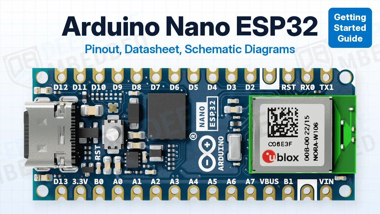
In this guide, you’ll find the Arduino Nano ESP32 pinout diagram (both Nano headers with the Arduino pin names and the ESP32-S3 GPIO numbers), the datasheet and schematic, and every pin group explained with its default pins and gotchas. Without further ado, let’s get right into it!
The Arduino Nano ESP32 (ABX00083) is the first Arduino board built on an ESP32. It packs u-blox’s NORA-W106 module with the ESP32-S3, a dual-core 240MHz Xtensa LX7 with Wi-Fi and Bluetooth LE, 16MB of flash and 8MB of PSRAM, into the classic Nano footprint with a USB-C port. It has 24 GPIO pins, all at 3.3v.
Arduino Nano ESP32 Pinout Diagram
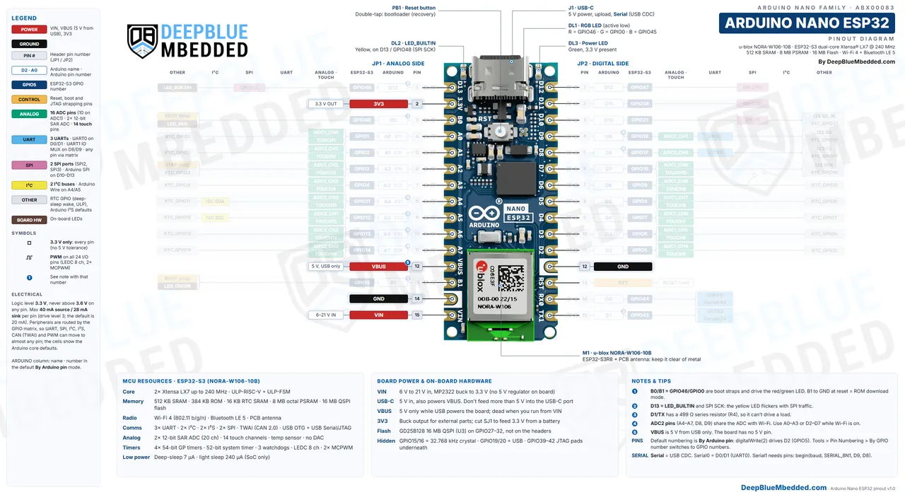
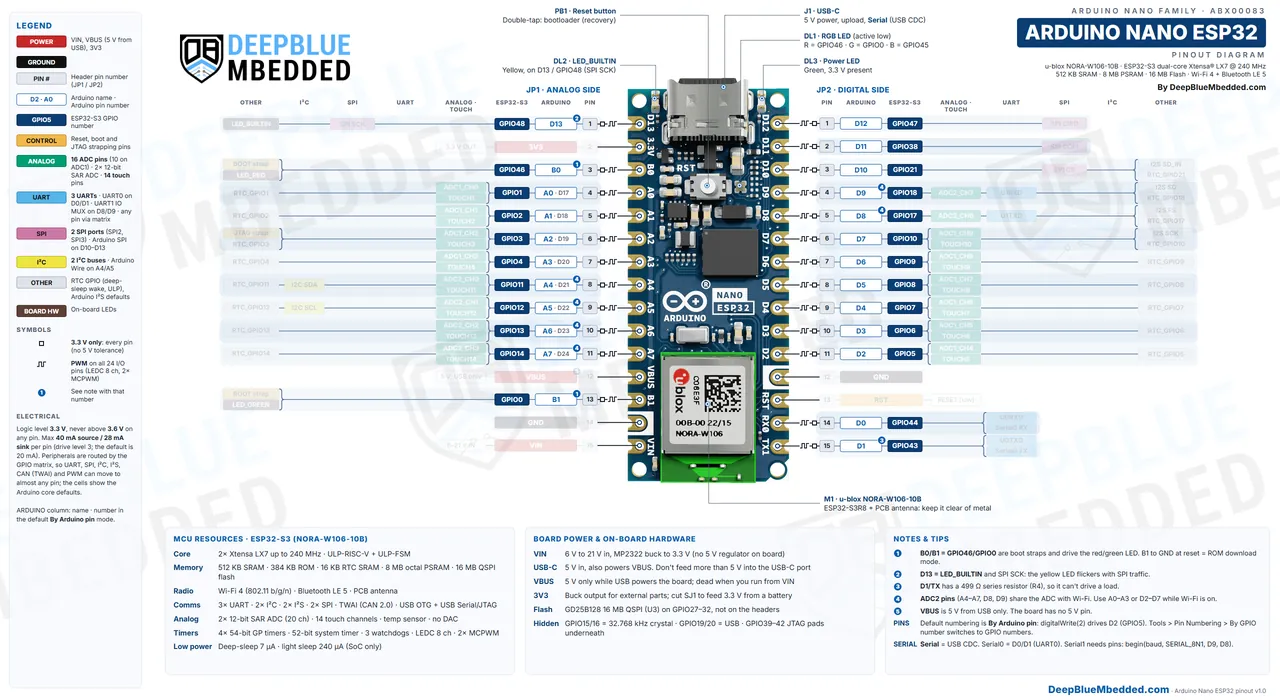
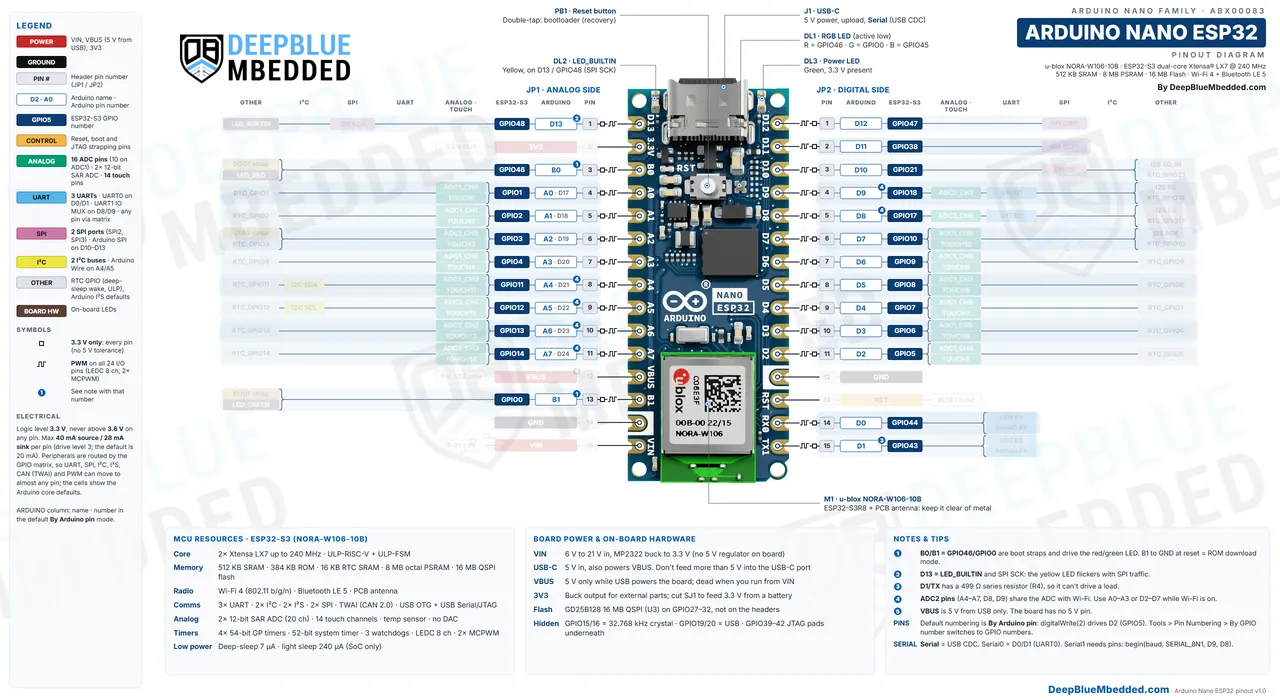
Here is a detailed Arduino Nano ESP32 Pinout Diagram with colored labels and legends to help you easily identify the functionalities that each pin can perform. It shows both 15-pin headers (JP1, the analog side, and JP2, the digital side) with the Arduino pin names, the ESP32-S3 GPIO numbers, and every pin’s ADC, touch, UART, SPI, I2C, PWM and strapping functions.
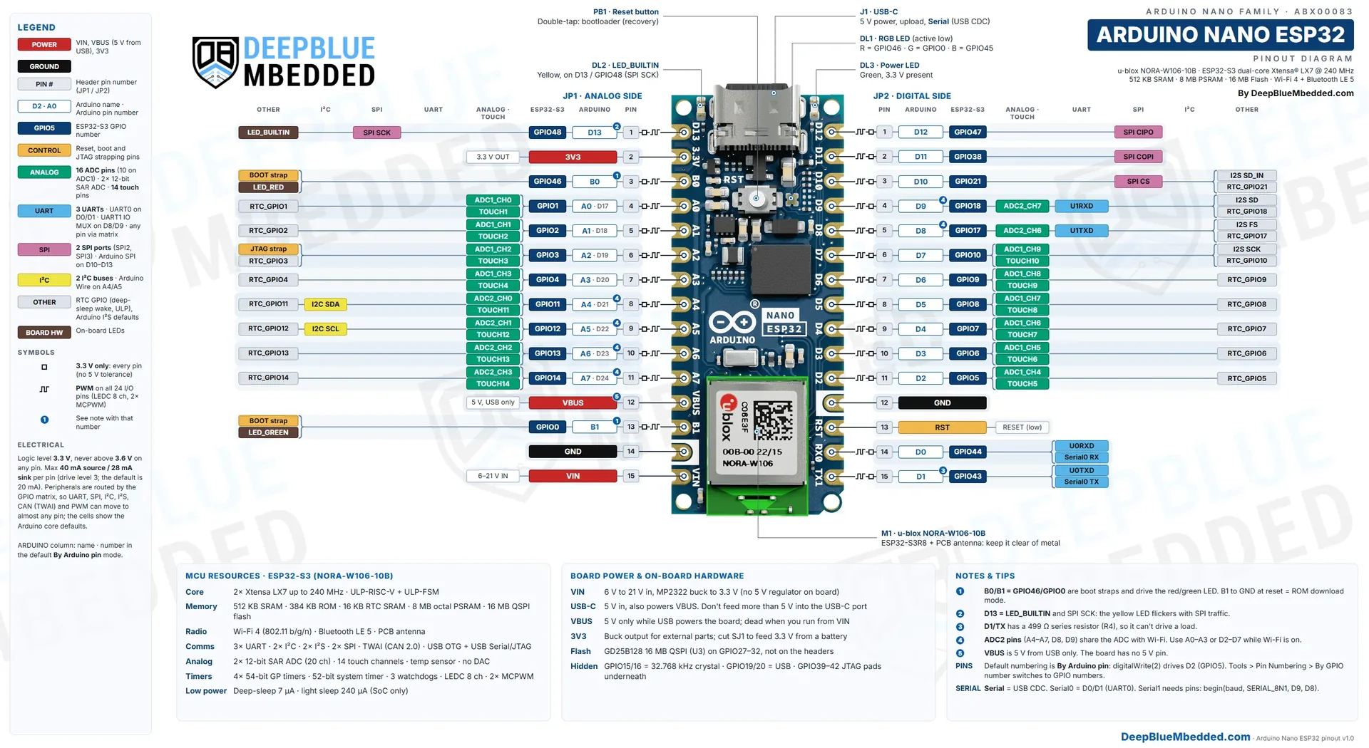
Each row shows the header pin number, the Arduino pin name (D2, A4…), the ESP32-S3 GPIO number, and its functions, color-coded by peripheral. The ARDUINO column is the number the Arduino IDE uses in its default pin-numbering mode (A2 is D19, for example). The square symbol means every pin is 3.3v only, the PWM symbol means every I/O can output PWM, and the numbered badges point to the notes at the bottom of the diagram.
With the USB-C connector at the top, JP1 (left) runs from D13 (pin 1) down to VIN (pin 15), and JP2 (right) runs from D12 (pin 1) down to D1/TX (pin 15), following the numbering in Arduino’s datasheet. The two rows are 15.24mm (600 mil) apart, like every Nano, so the board fits a breadboard and most Nano sockets.
Buy an Arduino Nano ESP32: If you don’t have one yet, you can get the genuine Arduino board (ABX00083, with headers) from Amazon or AliExpress. It runs the Arduino core, MicroPython and ESP-IDF right out of the box.
Download Arduino Nano ESP32 Pinout Diagram (Full Resolution)
The Arduino Nano ESP32 pinout diagram (JP1 and JP2 headers) in full resolution (5120×2800 px WebP), in one ZIP file. Print it, zoom in, or keep it next to your bench. Please consider supporting my work if it helped you.
Arduino Nano ESP32 Datasheet
This development board is built around the ESP32-S3 SoC, inside u-blox’s NORA-W106-10B module. So the Arduino Nano ESP32 datasheet set has three parts: Arduino’s documents for the board, Espressif’s for the chip, and u-blox’s for the module. Here are the official documents you’ll need, linked to their original sources:
| Document | ID | Revision | What You’ll Use It For | Link |
|---|---|---|---|---|
| Arduino Nano ESP32 datasheet (user manual) | ABX00083 | Rev 12 (Oct 2026) | Board specs, power options (VIN, VBUS, 3V3), pin current, header pin lists | |
| Arduino Nano ESP32 schematic | ABX00083 / ABX00092 | V0.3 (Jul 2023) | The full board circuit (see the next section) | |
| Arduino Nano ESP32 full pinout | ABX00083 | Dec 2023 | Arduino’s 4-page pin map, incl. the bottom test pads and the SJ1 jumper | |
| ESP32-S3 Series datasheet | Espressif | v2.2 | Pin functions (IO MUX, RTC, ADC, touch), strapping pins, electrical limits | |
| ESP32-S3 technical reference manual | Espressif | latest | Registers and how every peripheral and the GPIO matrix work | |
| ESP32-S3 Series SoC errata | Espressif | v1.3 | Silicon limitations (for example, no DMA on ADC2) | Web |
| NORA-W10 series data sheet | UBX-21036702 | R05 (Apr 2025) | The module: antenna, RF, temperature range, PSRAM |
Which document do I need? The Arduino datasheet for the board’s power limits and header map, the schematic for what’s connected to each pin, the ESP32-S3 datasheet for pin functions and electrical limits, and the technical reference manual when you write register-level code. Arduino keeps all its board files on the Arduino Nano ESP32 product page, and its Nano ESP32 user manual (cheat sheet) has the core-specific details.
Arduino Nano ESP32 Schematic
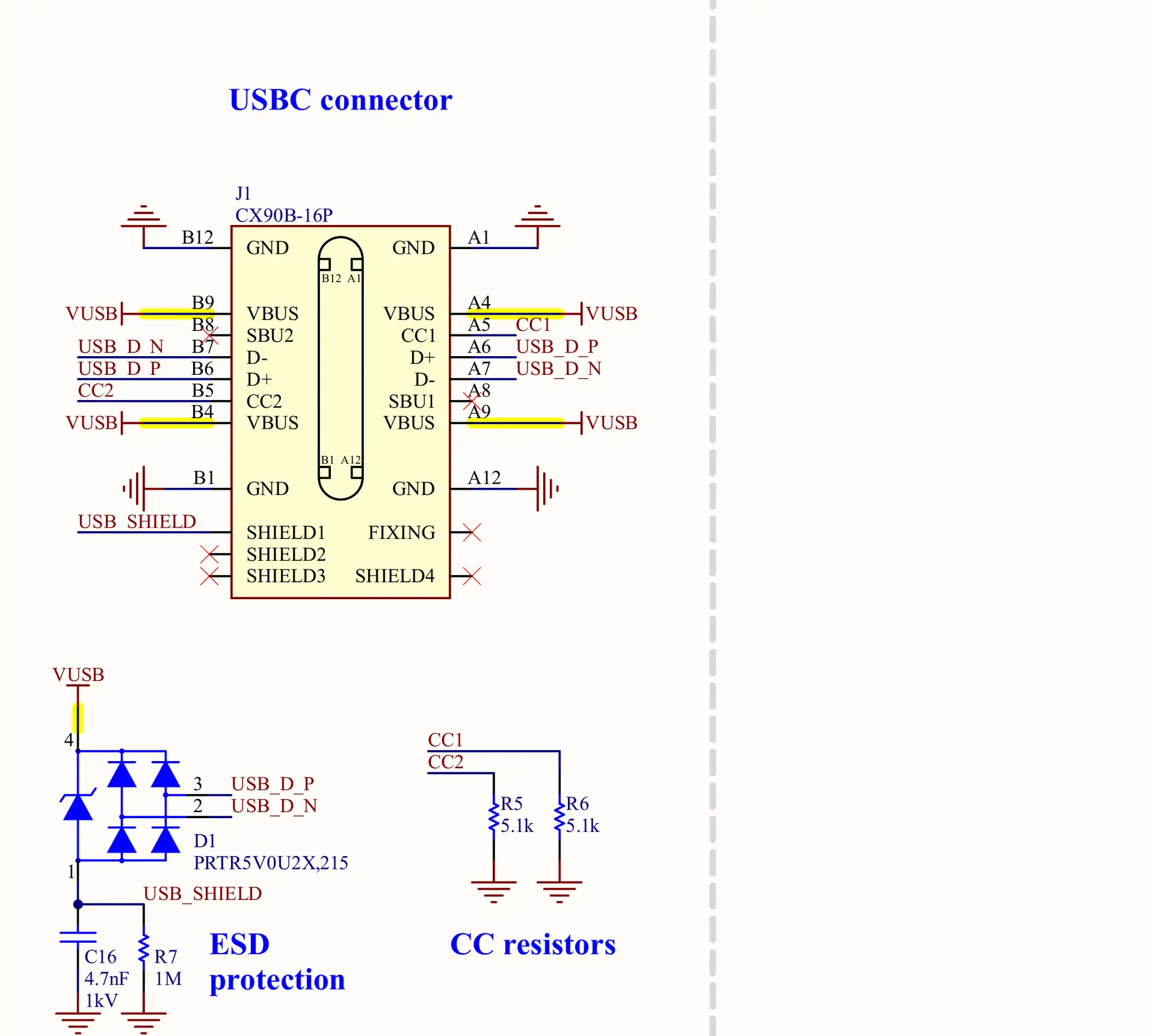
The Arduino Nano ESP32 schematic is Arduino’s ABX00083 / ABX00092 drawing, version V0.3 (7 Nov 2023), shared by the boards with and without headers. It’s one sheet, so here is the full sheet followed by close-ups of each block; click a page to view it full screen.
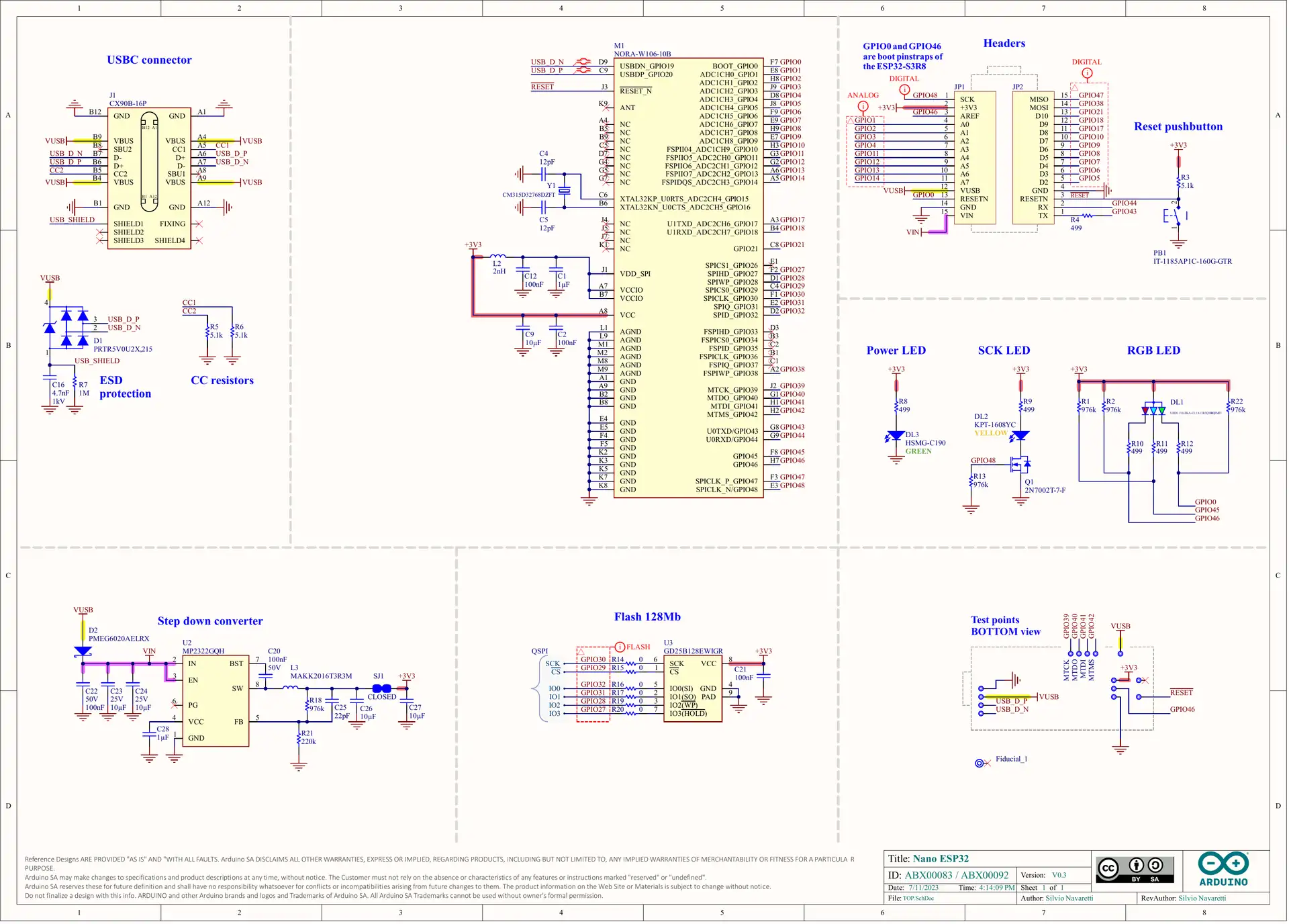
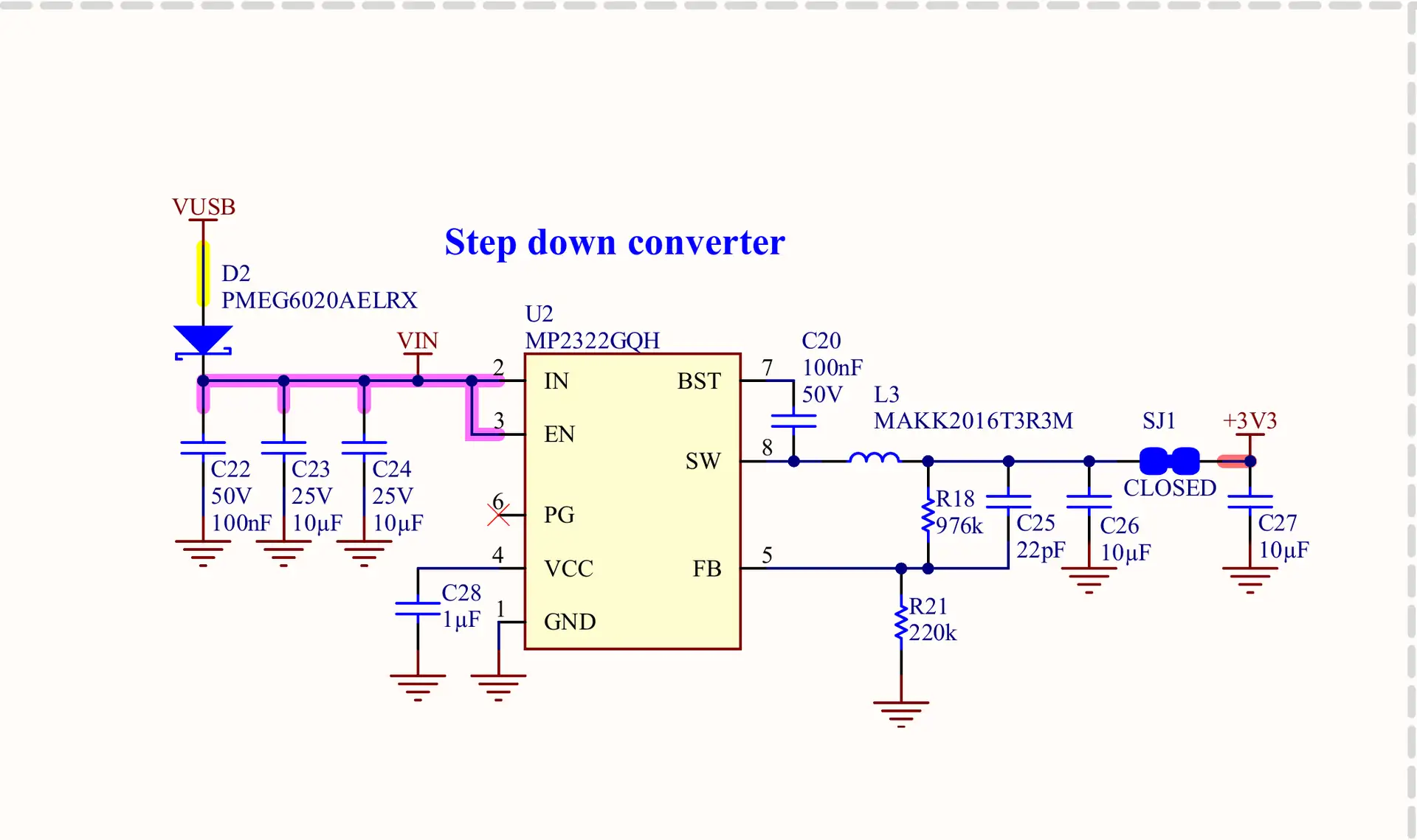
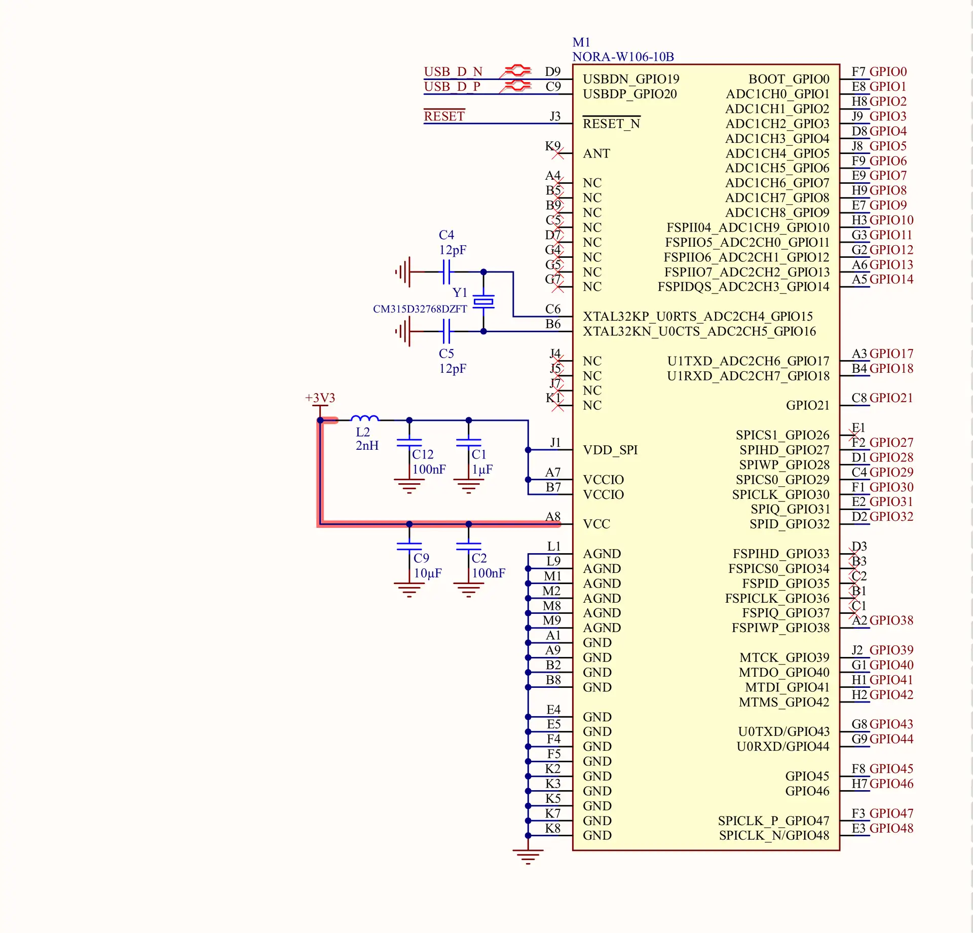
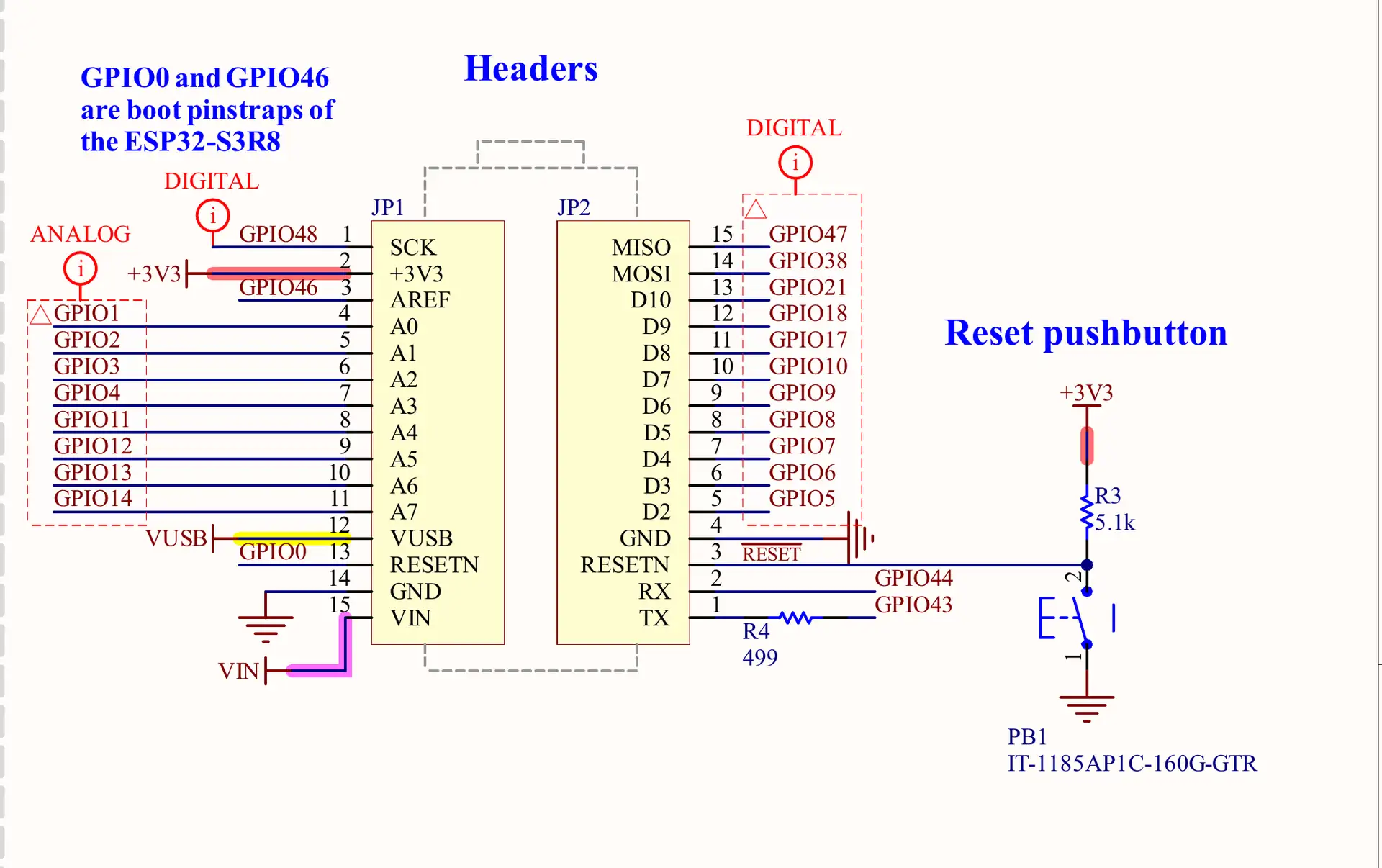
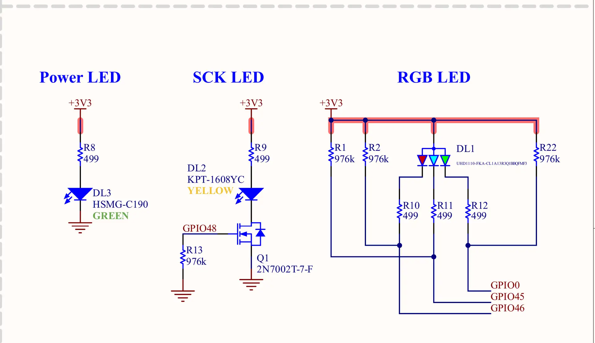
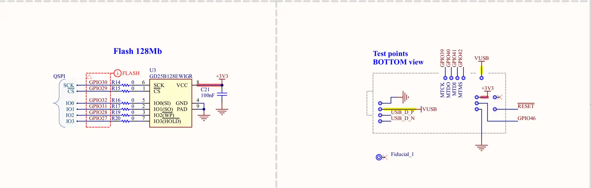
Official source: the Arduino Nano ESP32 schematic V0.3 (PDF) on Arduino Docs. Here’s what to look at:
- Power path: USB-C VBUS (net VUSB) and VIN (through the Schottky diode D2, PMEG6020) both feed the MP2322GQH step-down converter (U2), which makes the 3.3v rail for the module, the flash, the LEDs and the 3V3 pin. There’s no 5v regulator on the board.
- SJ1: a closed solder jumper between the buck output and the 3.3v rail. Cutting it lets you run the board from a battery on the 3V3 pin (Arduino’s full pinout, page 4).
- USB-C (J1): D+/D− go straight to the ESP32-S3’s own USB on GPIO19/GPIO20 through the PRTR5V0U2X ESD protection (D1), and CC1/CC2 have 5.1kΩ pull-downs, so any USB-C charger or port gives you 5v. There’s no USB-UART chip.
- NORA-W106-10B (M1): the ESP32-S3R8 with 8MB of octal PSRAM inside. The 32.768kHz crystal (Y1) sits on GPIO15/GPIO16, and the 16MB GD25B128EWIGR QSPI flash (U3) is on the internal flash pins, so none of those are on the headers.
- Headers: JP1 pin 3 (AREF on a classic Nano) is GPIO46 and JP1 pin 13 (RESET on a classic Nano) is GPIO0; the schematic notes that both are ESP32-S3 boot straps. D1/TX has the 499Ω series resistor R4, and RST has a 5.1kΩ pull-up (R3) and the reset button PB1.
- LEDs: the green power LED (DL3) on 3.3v, the yellow SCK LED (DL2) driven by the 2N7002 MOSFET Q1 from GPIO48 (so it doesn’t load the SPI clock), and the common-anode RGB LED (DL1) on GPIO46 (red), GPIO0 (green) and GPIO45 (blue), each through 499Ω with a 976kΩ pull-up.
- Test points (bottom): the JTAG pins GPIO39–GPIO42 (MTCK, MTDO, MTDI, MTMS), USB D+/D−, VUSB, 3V3, RESET and GPIO46, for debugging or factory programming.
Note: The schematic numbers JP2 from TX (pin 1) to MISO (pin 15), while the datasheet numbers it from D12 (pin 1) to D1/TX (pin 15); this article and the diagram follow the datasheet. The full pinout lists the RGB LED as D14–D16 on page 1 but swaps green and blue on page 3; the Arduino core says LED_GREEN = 15 and LED_BLUE = 16, so page 1 is right.
Arduino Nano ESP32 Specs
The Arduino Nano ESP32 is a Nano-size ESP32-S3 board from Arduino. Here are its specifications, including the board-level parts that chip-only spec lists usually skip.
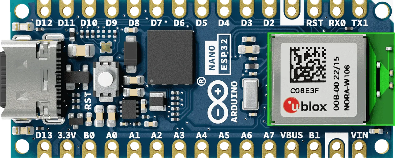
Get an Arduino Nano ESP32: The genuine Arduino board is the one I recommend. Grab it from Amazon or AliExpress.
| Item | Arduino Nano ESP32 |
|---|---|
| Module | u-blox NORA-W106-10B (ESP32-S3R8, PCB antenna) |
| CPU | Dual-core 32-bit Xtensa LX7, up to 240MHz, plus ULP-RISC-V and ULP-FSM coprocessors |
| Memory | 512KB SRAM, 384KB ROM, 16KB RTC SRAM, 8MB octal PSRAM (in the module), 16MB QSPI flash (GD25B128EWIGR) |
| Wireless | Wi-Fi 4 (802.11 b/g/n, 2.4GHz) and Bluetooth LE 5 |
| Logic level | 3.3v on every pin, not 5v tolerant (abs max 3.6v) |
| GPIO pins | 24 on the headers: D0–D13, A0–A7, B0, B1 |
| Board supply | USB-C 5v, or 6v–21v on VIN |
| 3.3v regulator | MP2322GQH synchronous step-down converter (U2); no 5v regulator and no 5V pin |
| Pin current | 40mA source, 28mA sink per GPIO (Arduino datasheet) |
| Clocks | 40MHz crystal in the module, 32.768kHz crystal (Y1) on GPIO15/GPIO16 |
| USB connector | USB-C, wired to the ESP32-S3’s native USB (USB Serial/JTAG + OTG); no USB-UART chip |
| Debugger | Built-in USB Serial/JTAG over the USB-C cable; JTAG test pads on the bottom |
| User I/O | RGB LED (GPIO46/0/45, active low), yellow LED on D13, green power LED, reset button |
| Form factor | Arduino Nano, 18 × 45mm, 2x 15-pin headers (castellated pads) |
| Order codes | ABX00083 (with headers), ABX00092 (without headers) |
| No | DAC, 5v-tolerant pins, 5V output pin (VBUS is 5v only on USB power) |
Arduino Nano ESP32 Specifications Summary
- The Arduino Nano ESP32 runs an ESP32-S3 at up to 240MHz (dual-core Xtensa LX7) with 512KB SRAM, 8MB PSRAM and 16MB flash.
- It has 24 GPIOs on the headers (D0–D13, A0–A7, B0, B1), and every pin is 3.3v only: none of them is 5v tolerant.
- The Arduino core numbers the pins By Arduino pin by default (D2 = 2, A0 = 17); By GPIO number (legacy) switches to raw ESP32-S3 GPIO numbers.
- It has 16 ADC pins (12-bit): 10 on ADC1 (A0–A3, D2–D7), which work with Wi-Fi, and 6 on ADC2 (A4–A7, D8, D9), which can fail while Wi-Fi is on.
- It has 14 capacitive touch pins (A0–A7, D2–D7) and no DAC.
- All 24 I/O pins can output PWM (LEDC with 8 channels, plus 2x MCPWM).
- Serial is USB CDC on the USB-C port; Serial0 is UART0 on D0 (RX) / D1 (TX); Serial1 has no default header pins.
- The Arduino Wire pins are A4 (SDA) and A5 (SCL); SPI is D11 (COPI), D12 (CIPO), D13 (SCK) with D10 as CS.
- Power it from USB-C (5v) or VIN (6v–21v). There’s no 5V pin: VBUS gives 5v only while USB powers the board.
- B0 (GPIO46) and B1 (GPIO0) are boot strapping pins and drive the red and green RGB LED. B1 to GND at reset starts the ROM download mode.
- Each GPIO can source 40mA and sink 28mA, and D1/TX has a 499Ω series resistor.
Arduino Nano ESP32 Peripherals: ESP32-S3 vs On the Headers
The ESP32-S3 routes almost every peripheral through its GPIO matrix, so UART, I2C, SPI, PWM, CAN and I2S can go to nearly any free pin. This table shows what the chip has and what you can actually reach on the Nano headers.
| Peripheral | ESP32-S3 | On the Nano ESP32 Headers |
|---|---|---|
| GPIO | 45 GPIOs | 24 (D0–D13, A0–A7, B0, B1) |
| ADC | 2x 12-bit SAR ADC, 20 channels | 16 pins: 10 on ADC1 (A0–A3, D2–D7), 6 on ADC2 (A4–A7, D8, D9) |
| Touch | 14 capacitive touch pads | all 14 (A0–A7, D2–D7) |
| DAC | none | – |
| UART | 3 | UART0 on D0/D1; UART1 and UART2 on any pin via the matrix (D9/D8 are UART1’s IO MUX pins) |
| SPI (general purpose) | SPI2, SPI3 | Arduino SPI on D10–D13; a second bus on any pins |
| I2C | 2 | Arduino Wire on A4/A5; Wire1 on any pins |
| I2S | 2 | Arduino defaults D7 (SCK), D8 (FS), D9 (SD), D10 (SD in) |
| TWAI (CAN 2.0) | 1 | any pin, with an external CAN transceiver |
| PWM | LEDC (8 channels), 2x MCPWM | all 24 I/O pins |
| USB | USB OTG Full-Speed + USB Serial/JTAG | on the USB-C connector only (GPIO19/GPIO20) |
| RMT, PCNT, LCD, camera, SD/MMC | yes | any free pins |
Arduino Nano ESP32 Quick Pin Selection Guide
Not sure which pin to use? Here are the Arduino Nano ESP32 pins I’d pick first for each job, and why.
| Use Case | Recommended Pins | Why |
|---|---|---|
| Serial to the PC | USB-C (Serial) | USB CDC on the native USB; no adapter needed |
| Serial to a module (GPS, GSM…) | D0 (RX), D1 (TX) as Serial0, or D9/D8 as Serial1 | UART0 is fixed on D0/D1; give Serial1 its pins in begin() |
| I2C sensors and displays | A4 (SDA), A5 (SCL) | The Arduino Wire pins; add 4.7kΩ pull-ups if the module has none |
| SPI devices | D11 (COPI), D12 (CIPO), D13 (SCK), D10 (CS) | The Arduino SPI pins; D13 also blinks the yellow LED |
| Analog inputs with Wi-Fi on | A0, A1, A2, A3, D2–D7 | ADC1 pins keep working while Wi-Fi runs |
| PWM (LEDs, motors, servos) | D2–D9 | Any pin works; these have no strapping or bus role |
| Touch buttons | A0–A3, D2–D7 | Touch pads that don’t clash with I2C |
| External interrupt | Any GPIO (D2–D9 first) | Every ESP32-S3 GPIO can trigger an interrupt |
| On-board LEDs | LED_BUILTIN (D13), LED_RED / LED_GREEN / LED_BLUE | The RGB LED is active low |
| Safest general GPIO | D2–D7 | No strapping role, no board load, ADC1 + touch capable |
Arduino Nano ESP32 Pins to Use With Caution
| Pin | Reason | What to Do |
|---|---|---|
| B1 (GPIO0) | Boot strap: LOW at reset starts ROM download mode; also the green LED | Don’t pull it LOW at reset; use it as an output or a button input with care |
| B0 (GPIO46) | Boot strap (must not be HIGH while GPIO0 is LOW at reset); also the red LED | Don’t pull it HIGH at reset; it also lights the red LED, so it’s best as an output |
| A2 (GPIO3) | JTAG-source strap (only read if the eFuse is set) | Safe for normal use; avoid strong pulls at reset |
| D1 / TX (GPIO43) | 499Ω series resistor on the board | Use it for UART only, not to drive LEDs or loads |
| D13 (GPIO48) | SPI SCK and the yellow LED (via MOSFET) | Fine as SCK; the LED blinks with SPI traffic |
| A4–A7, D8, D9 | ADC2 pins: reads can fail while Wi-Fi is on | Use ADC1 pins for analog with Wi-Fi |
| All pins | 3.3v only, no 5v tolerance | Level-shift every 5v signal |
| VBUS | Only 5v when USB powers the board | Don’t count on it with VIN power |
Arduino Nano ESP32 Pin Numbering: Arduino Pins vs ESP32-S3 GPIO Numbers
The Arduino Nano ESP32 has two pin-numbering modes in the Arduino IDE. By default (Tools > Pin Numbering > By Arduino pin), the numbers follow the Nano silkscreen: digitalWrite(2, HIGH) drives D2, which is GPIO5. In By GPIO number (legacy) mode, the same number means the raw ESP32-S3 GPIO, so 2 is GPIO2, which is A1.
| Board Pin | Arduino Number (Default) | ESP32-S3 GPIO (Legacy Mode) | Board Pin | Arduino Number (Default) | ESP32-S3 GPIO (Legacy Mode) |
|---|---|---|---|---|---|
| D0 / RX0 | 0 | GPIO44 | A0 | 17 | GPIO1 |
| D1 / TX | 1 | GPIO43 | A1 | 18 | GPIO2 |
| D2 | 2 | GPIO5 | A2 | 19 | GPIO3 |
| D3 | 3 | GPIO6 | A3 | 20 | GPIO4 |
| D4 | 4 | GPIO7 | A4 (SDA) | 21 | GPIO11 |
| D5 | 5 | GPIO8 | A5 (SCL) | 22 | GPIO12 |
| D6 | 6 | GPIO9 | A6 | 23 | GPIO13 |
| D7 | 7 | GPIO10 | A7 | 24 | GPIO14 |
| D8 | 8 | GPIO17 | B0 / LED_RED | 14 | GPIO46 |
| D9 | 9 | GPIO18 | B1 / LED_GREEN | 15 | GPIO0 |
| D10 (CS) | 10 | GPIO21 | LED_BLUE (no pin) | 16 | GPIO45 |
| D11 (COPI) | 11 | GPIO38 | |||
| D12 (CIPO) | 12 | GPIO47 | |||
| D13 (SCK) | 13 | GPIO48 |
The safe habit is to always write the pin names ( D2, A0, LED_RED) instead of bare numbers. The core defines those constants for both modes (arduino_nano_nora variant), so your sketch drives the same pin either way.
Note: Libraries that talk to the ESP-IDF directly (OneWire/DS18B20, some Servo, LED strip and stepper libraries) expect GPIO numbers. In the default mode they can drive the wrong pin, which is the most common “half my pins don’t work” report on the Arduino forum. Switch to By GPIO number (legacy) for those sketches, or update the library (Arduino: Nano ESP32 pin setup). In arduino-cli, the board option is PinNumbers=byGPIONumber.
Arduino Nano ESP32 Pins Functions
The 30 header pins of the Arduino Nano ESP32 are divided into the following groups based on the hardware functionality they’re used for. Thanks to the ESP32-S3’s GPIO matrix, most pins belong to several groups at once.
- Power Pins: VIN, VBUS, 3V3, 2x GND, RST
- 24x Digital GPIO Pins
- 24x Interrupt Pins (every GPIO)
- 16x ADC Analog Input Pins (10x ADC1, 6x ADC2)
- 14x Capacitive Touch Pins
- 24x PWM Pins
- 3x UART Ports (+ USB CDC)
- 2x I2C Buses
- 2x SPI Ports
- 2x I2S & 1x CAN (TWAI)
- 1x Native USB Port (USB-C)
- Strapping & Boot Pins: B0, B1, A2
We’ll discuss each pin group in the following sections one by one in more detail.
Arduino Nano ESP32 Power Pins
The Arduino Nano ESP32 is powered from the USB-C port (5v) or from 6v–21v on VIN. Both go into the MP2322GQH step-down converter, which makes the 3.3v rail. There’s no 5V pin: the VBUS pin gives 5v only while USB powers the board. The power pins are highlighted in red in the pinout diagram.
| Pin | Header Pin | Range | Notes |
|---|---|---|---|
| VIN | JP1-15 | 6v–21v in | Through Schottky diode D2 into the buck converter (Arduino datasheet 11.3) |
| VBUS | JP1-12 | 5v out (USB only) | Straight from the USB-C connector; off when you power the board from VIN |
| 3V3 | JP1-2 | 3.3v out | Buck converter output, for sensors and modules; battery input if you cut SJ1 |
| GND | JP1-14, JP2-12 | 0v | All grounds are common |
| RST | JP2-13 | 3.3v logic | Pull LOW to reset (5.1kΩ pull-up on the board) |
The buck converter is efficient: Arduino quotes more than 90% at a 4.5v input, 85–90% at 12v and below 85% at 18v. So a 7.4v or 12v battery on VIN is a much better choice than it is on a classic Nano’s linear regulator. Don’t feed more than 5v into the USB-C port, and never more than 21v into VIN.
Note: The Nano ESP32 is the first Nano without a 5V pin. If you move a project from a classic Nano, any module wired to “5V” must now go to VBUS (USB power only) or to its own 5v supply. And every signal pin is 3.3v: a 5v sensor output needs a level shifter or a voltage divider.
For battery projects, the ESP32-S3 draws about 7µA in deep sleep and 240µA in light sleep (SoC only; the board’s LEDs and buck converter add to that).
Learn more in our ESP32 Sleep Modes & Power Consumption Guide.
Arduino Nano ESP32 GPIO Pins
The Arduino Nano ESP32 has 24 GPIO pins on its headers: D0–D13, A0–A7, B0 and B1. They all work at 3.3v, and none of them is 5v tolerant. A0–A7 are also digital pins 17–24 in the default numbering mode.
Each GPIO can be an input (floating, pull-up or pull-down, about 45kΩ internal), a push-pull or open-drain output, or almost any peripheral through the GPIO matrix. Here are the limits from the Arduino and Espressif datasheets:
- Logic level 3.3v; never apply more than 3.6v to any pin.
- Up to 40mA source and 28mA sink per pin (at the strongest drive setting). The default drive strength is 20mA, and only 10mA on D8/D9 (GPIO17/GPIO18).
- D1/TX has a 499Ω series resistor, so it can’t drive a load directly.
- The pins you don’t see: GPIO15/16 (32.768kHz crystal), GPIO19/20 (USB), GPIO26–32 (flash), GPIO33–37 (PSRAM) and GPIO39–42 (JTAG pads on the bottom).
Note: The ESP32-S3 has no 5v-tolerant pins at all. Connecting a 5v Arduino module’s output straight to a Nano ESP32 pin can damage the chip, so use a level shifter (or a resistor divider for slow inputs).
Learn more in our ESP32 GPIO Tutorial.

Also Read
Arduino Nano ESP32 Interrupt Pins
Every GPIO pin on the Arduino Nano ESP32 can be an external interrupt pin: all 24 of them support RISING, FALLING, CHANGE, LOW and HIGH triggers. In the Arduino core, attachInterrupt(digitalPinToInterrupt(D2), isr, FALLING) works on any of them.
The RTC GPIOs (A0–A7, B1, D2–D10) can also wake the ESP32-S3 from deep sleep (EXT0/EXT1 wake-up), and the touch pins can wake it with a touch.
|
1 2 3 4 5 6 7 8 9 10 11 12 |
volatile bool pressed = false; void IRAM_ATTR onPress() { pressed = true; } void setup() { Serial.begin(115200); pinMode(D2, INPUT_PULLUP); // button from D2 to GND attachInterrupt(digitalPinToInterrupt(D2), onPress, FALLING); } void loop() { if (pressed) { pressed = false; Serial.println("Button pressed"); } } |
Learn more in our ESP32 External Interrupts Tutorial.
Also Read
Arduino Nano ESP32 ADC Pins
The Arduino Nano ESP32 has 16 ADC pins on two 12-bit SAR ADCs. ADC1 has 10 of them (A0–A3 and D2–D7) and keeps working with Wi-Fi on. ADC2 has the other 6 (A4–A7, D8, D9), and its reads can fail while Wi-Fi is running. The ADC pins are highlighted in green in the pinout diagram.
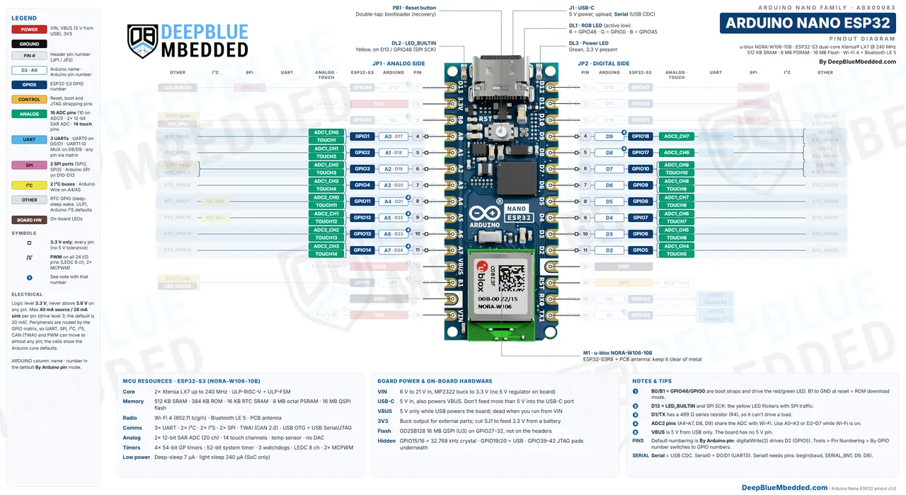
| Pin | GPIO | ADC Channel | Works With Wi-Fi? | Pin | GPIO | ADC Channel | Works With Wi-Fi? |
|---|---|---|---|---|---|---|---|
| A0 | GPIO1 | ADC1_CH0 | Yes | D2 | GPIO5 | ADC1_CH4 | Yes |
| A1 | GPIO2 | ADC1_CH1 | Yes | D3 | GPIO6 | ADC1_CH5 | Yes |
| A2 | GPIO3 | ADC1_CH2 | Yes | D4 | GPIO7 | ADC1_CH6 | Yes |
| A3 | GPIO4 | ADC1_CH3 | Yes | D5 | GPIO8 | ADC1_CH7 | Yes |
| A4 | GPIO11 | ADC2_CH0 | Can fail | D6 | GPIO9 | ADC1_CH8 | Yes |
| A5 | GPIO12 | ADC2_CH1 | Can fail | D7 | GPIO10 | ADC1_CH9 | Yes |
| A6 | GPIO13 | ADC2_CH2 | Can fail | D8 | GPIO17 | ADC2_CH6 | Can fail |
| A7 | GPIO14 | ADC2_CH3 | Can fail | D9 | GPIO18 | ADC2_CH7 | Can fail |
Why ADC2? On the ESP32-S3, the Wi-Fi driver also uses ADC2, so Espressif’s ADC driver says a read “may fail” with a timeout while Wi-Fi holds it. And the S3 errata (ADC-183) says ADC2’s DMA controller doesn’t work, so continuous (DMA) sampling is ADC1 only. analogRead() returns 0 to 4095 (12-bit), and with the default attenuation the datasheet’s accurate range ends at about 2.9v, so readings flatten out near the 3.3v top.
Note: Use A0–A3 or D2–D7 for analog sensors in any Wi-Fi or IoT project. A4/A5 are the default I2C pins too, so on the Arduino Nano ESP32 they’re a poor choice for analog in most projects anyway. Never apply more than 3.3v to an ADC pin; use a voltage divider for higher voltages.
There are so many sensors that we can read with the ADC pins, which include: potentiometers, LDRs, analog temperature sensors (LM35, NTC thermistors), soil moisture sensors, joysticks, current sensors, and much more.
|
1 2 3 4 5 6 7 8 9 10 11 |
void setup() { Serial.begin(115200); analogReadResolution(12); // 0..4095 } void loop() { int raw = analogRead(A0); // ADC1: safe with Wi-Fi int mv = analogReadMilliVolts(A0); // calibrated millivolts Serial.printf("A0: %d (%d mV)\n", raw, mv); delay(500); } |
Learn more in our ESP32 ADC Tutorial.
Also Read
Arduino Nano ESP32 Touch Pins
The Arduino Nano ESP32 has 14 capacitive touch pins: A0–A7 (TOUCH1–4, TOUCH11–14) and D2–D7 (TOUCH5–10). Connect a wire, a copper pad or a piece of foil, and touchRead(D2) returns a value that rises when you touch it (on the ESP32-S3, the opposite of the classic ESP32). They can also wake the board from deep sleep.
Arduino Nano ESP32 PWM Pins
All 24 GPIO pins on the Arduino Nano ESP32 can output PWM. The ESP32-S3’s LEDC peripheral has 8 independent channels, and there are 2 MCPWM units for motor control, routed to any pin through the GPIO matrix. In the Arduino core, analogWrite(D5, 128) just works.
Arduino Nano ESP32 PWM Pins: D0–D13, A0–A7, B0 and B1 (8 LEDC channels at a time).
For more control, use the LEDC API: ledcAttach(D5, 5000, 10) sets 5kHz with 10-bit resolution, and ledcWrite(D5, 512) sets 50% duty. Higher frequencies leave fewer resolution bits. Since there are 8 LEDC channels, you can run up to 8 different PWM outputs at once.
There are so many things that we can control with PWM, which include: LED dimming, RGB LEDs, DC motor speed (with a driver), servo motors, buzzers, ESCs for brushless motors, and much more.
Learn more in our ESP32 PWM Tutorial.
Also Read
Arduino Nano ESP32 UART Pins
The Arduino Nano ESP32 has 3 hardware UARTs, plus the USB CDC port. Serial is the USB-C port (to the Serial Monitor), Serial0 is UART0 on D0 (RX) and D1 (TX), and Serial1/ Serial2 can go to any pins you choose. The UART pins are highlighted in blue in the pinout diagram.
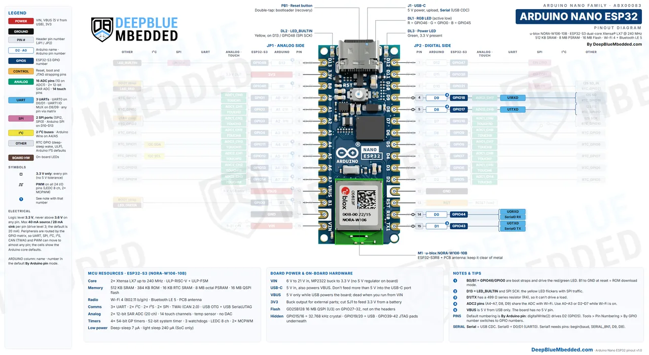
Arduino Nano ESP32 Default UART Pins: D0 (RX) and D1 (TX) for Serial0.
| Port | Arduino Object | RX Pin | TX Pin | Note |
|---|---|---|---|---|
| USB CDC | Serial | USB-C | USB-C | Serial Monitor over the USB cable |
| UART0 | Serial0 | D0 (GPIO44) | D1 (GPIO43) | Fixed IO MUX pins; 499Ω resistor on TX |
| UART1 | Serial1 | D9 (GPIO18) suggested | D8 (GPIO17) suggested | No default header pins: pass them in begin() |
| UART2 | Serial2 | any free pin | any free pin | Through the GPIO matrix |
The ESP32-S3 core’s default pins for UART1 are GPIO15/GPIO16, and on this board those are the 32.768kHz crystal pins, which aren’t on the headers. So always give Serial1 its pins. D9/D8 are UART1’s own IO MUX pins, and Arduino’s pinout labels them RX1/TX1:
|
1 2 3 4 5 6 7 8 9 |
void setup() { Serial.begin(115200); // USB-C to the PC Serial1.begin(9600, SERIAL_8N1, D9, D8); // RX = D9, TX = D8 } void loop() { while (Serial1.available()) Serial.write(Serial1.read()); // module -> PC while (Serial.available()) Serial1.write(Serial.read()); // PC -> module } |
Note: Use the pin constants (D9, D8) in begin(), not the numbers 9 and 8: the core maps the constants correctly in both pin-numbering modes. And remember the logic level: a 5v module’s TX needs a level shifter before it reaches a Nano ESP32 RX pin.
There are so many modules that we can interface with the UART pins, which include: GPS modules, GSM/LTE modules, fingerprint sensors, RS485 transceivers, DFPlayer Mini, other microcontrollers, and much more.
Learn more in our ESP32 Serial Print Tutorial.
Also Read
Arduino Nano ESP32 I2C Pins
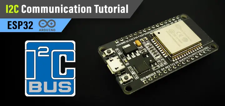
The Arduino Nano ESP32 has 2 I2C buses. The default Arduino Wire pins are A4 (SDA) and A5 (SCL), the same place as on every Nano. The second bus, Wire1, can use any free pins. The I2C pins are highlighted in yellow in the pinout diagram.
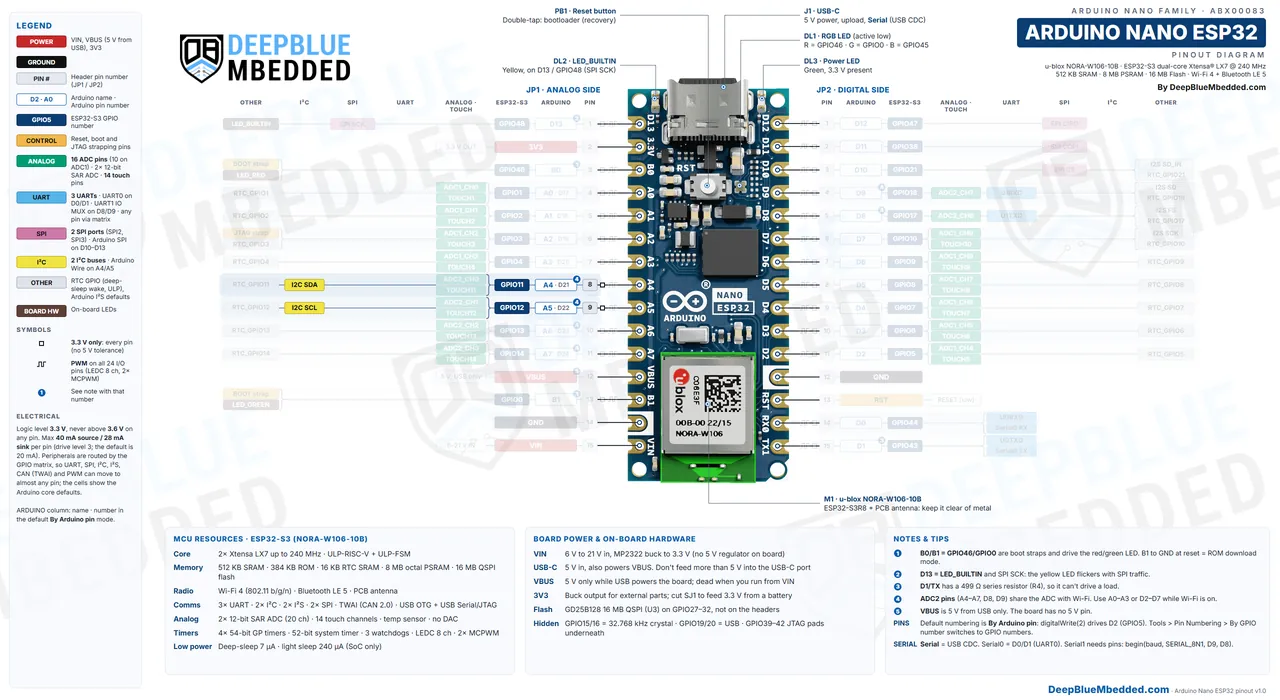
Arduino Nano ESP32 Default I2C Pins: A4 (SDA) and A5 (SCL).
| I2C Bus | Arduino Object | SDA | SCL | Note |
|---|---|---|---|---|
| I2C0 | Wire | A4 (GPIO11) | A5 (GPIO12) | Default; most libraries assume it |
| I2C1 | Wire1 | any free pin | any free pin | For example D4 (SDA) and D5 (SCL) |
|
1 2 3 4 5 6 7 8 |
#include <Wire.h> void setup() { Wire.begin(); // SDA = A4, SCL = A5 Wire1.begin(D4, D5); // second bus: SDA = D4, SCL = D5 } void loop() {} |
Note: There are no I2C pull-up resistors on the Nano ESP32, so add 4.7kΩ pull-ups to 3.3v (not 5v) unless your module already has them. A4 and A5 are also ADC2 pins, so you can’t use them for analog while the I2C bus is on them.
There are so many modules and sensors that we can interface with the I2C bus, which include: OLED displays (SSD1306), I2C LCDs, RTC modules (DS3231), IMUs (MPU6050), BME280 sensors, port expanders, and much more.
Learn more in our ESP32 I2C Tutorial.
Also Read
Arduino Nano ESP32 SPI Pins
The Arduino Nano ESP32 has 2 general-purpose SPI ports (SPI2 and SPI3). The default Arduino SPI pins are D11 (COPI), D12 (CIPO) and D13 (SCK), with D10 as CS, matching the classic Nano. The SPI pins are highlighted in pink in the pinout diagram.
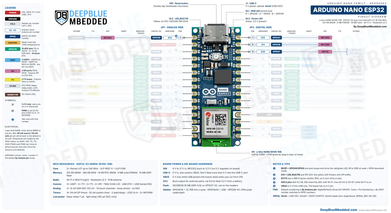
Arduino Nano ESP32 Default SPI Pins: D11 (COPI/MOSI), D12 (CIPO/MISO), D13 (SCK), and D10 (CS).
| Signal | Pin | GPIO | Note |
|---|---|---|---|
| SCK | D13 | GPIO48 | Also LED_BUILTIN (yellow LED, through a MOSFET) |
| CIPO (MISO) | D12 | GPIO47 | |
| COPI (MOSI) | D11 | GPIO38 | |
| CS (SS) | D10 | GPIO21 | Any GPIO can be an extra CS |
The second SPI port can go to any free pins: create an SPIClass on the other host and call begin(sck, miso, mosi, cs) with the pin constants. The 16MB flash and the PSRAM use the chip’s separate memory SPI bus, so both SPI ports are free for you.
Note: The yellow LED on D13 blinks with every SPI transfer. That’s normal, and because a MOSFET drives the LED, it doesn’t slow down or load the SCK line.
There are so many modules that we can interface with the SPI bus, which include: TFT displays (ILI9341, ST7789), SD card modules, LoRa radios (SX1276), nRF24L01 radios, MAX7219 LED drivers, W5500 Ethernet modules, and much more.
Arduino Nano ESP32 I2S and CAN (TWAI) Pins
The Arduino Nano ESP32 has 2 I2S controllers for digital audio and 1 TWAI controller (CAN 2.0, no CAN FD). Both go through the GPIO matrix. The Arduino core’s default I2S pins are D7 (SCK), D8 (FS), D9 (SD) and D10 (SD in).
| Interface | Default / Suggested Pins | Note |
|---|---|---|
| I2S SCK (BCLK) | D7 (GPIO10) | Core default |
| I2S FS (WS / LRCLK) | D8 (GPIO17) | Core default |
| I2S SD (data out) | D9 (GPIO18) | Core default |
| I2S SD in | D10 (GPIO21) | Core default; clashes with SPI CS if you use both |
| CAN TX / RX (TWAI) | any two free pins, for example D4 / D5 | Needs a 3.3v CAN transceiver (SN65HVD230 or similar) |
I2S is how you connect I2S microphones (INMP441), DACs and amplifiers (MAX98357A, PCM5102). The TWAI controller talks to CAN buses in cars and industrial gear, but it needs an external transceiver, since the board has none.
Arduino Nano ESP32 USB Pins
The Arduino Nano ESP32’s USB-C connector is wired straight to the ESP32-S3’s native USB on GPIO19 (D−) and GPIO20 (D+). There’s no USB-UART chip: the same port does the uploads (DFU), the Serial port (CDC), debugging (USB Serial/JTAG), and USB device modes like HID keyboard and mouse.
| Signal | GPIO | On This Board |
|---|---|---|
| USB D− | GPIO19 | USB-C connector only (not on the headers) |
| USB D+ | GPIO20 | USB-C connector only (not on the headers) |
| VBUS | – | VBUS pin (JP1-12) and the buck converter input |
Because USB is handled by the ESP32-S3 itself, a sketch that crashes early or uses the USB pins wrongly can make the port disappear. That’s what the double-tap reset and the bootloader recovery in the next section are for.
Arduino Nano ESP32 Strapping and Boot Pins
The Arduino Nano ESP32 has 3 strapping pins on its headers: B1 (GPIO0), B0 (GPIO46) and A2 (GPIO3). The ESP32-S3 reads them at reset to pick the boot mode, so an external circuit that forces them LOW or HIGH at power-up can stop the board from booting. The fourth strap, GPIO45, is the blue RGB LED line.
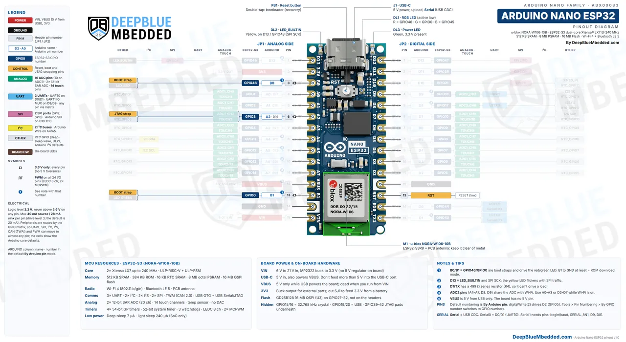
| Pin | GPIO | Strapping Role | On the Board |
|---|---|---|---|
| B1 | GPIO0 | LOW at reset = ROM download (serial/USB) boot | 976kΩ pull-up, green LED (499Ω) |
| B0 | GPIO46 | Must not be HIGH while GPIO0 is LOW at reset | 976kΩ pull-up, red LED (499Ω) |
| A2 | GPIO3 | JTAG source select (only if the eFuse is set) | Free analog/touch pin |
| (blue LED) | GPIO45 | VDD_SPI voltage select | 976kΩ pull-up (weaker than the internal pull-down) |
| RST | RESET_N | Reset | 5.1kΩ pull-up, RST button to GND |
B0 and B1 sit exactly where a classic Nano has AREF and RESET. That’s why some Nano shields and I/O expansion boards that tie those positions to something can keep a Nano ESP32 from booting or being recognized: check what your shield does with AREF and RESET before you plug the board in.
Arduino Nano ESP32 Bootloader Recovery Steps
If your Arduino Nano ESP32 isn’t detected anymore (no COM port after uploading a sketch), use these two steps, in this order:
- Double-tap reset: press the RST button twice quickly, right after plugging the board in. The RGB LED starts fading, and the board stays in the Arduino bootloader (DFU), so you can upload a working sketch.
- ROM download mode (if the bootloader is damaged): short B1 to GND with a jumper wire, press RST, then remove the wire (the RGB LED turns green). In the Arduino IDE, select Tools > Programmer > Esptool, then Tools > Burn Bootloader. Press RST when it’s done, and upload a sketch as usual.
Arduino describes the same procedure in its Help Center article Reset the Arduino bootloader on the Nano ESP32.
Note: Debugging also runs over the USB-C cable: the ESP32-S3’s built-in USB Serial/JTAG works with OpenOCD in Arduino IDE 2 (Sketch > Optimize for Debugging, then Start Debugging). The JTAG pins GPIO39–42 are only on test pads under the board.
Arduino Nano ESP32 On-Board Features
Besides the headers, the Arduino Nano ESP32 has 3 LEDs (one of them RGB), a reset button, two crystals, and a solder jumper. Here’s what each one does.
| Part | Pin / Connection | What It Does |
|---|---|---|
| RGB LED (DL1) | Red GPIO46 (B0), green GPIO0 (B1), blue GPIO45 | Common anode, active LOW: digitalWrite(LED_RED, LOW) turns red on |
| Yellow LED (DL2) | D13 / GPIO48 via MOSFET Q1 | LED_BUILTIN, active HIGH; blinks with SPI SCK |
| Green power LED (DL3) | 3.3v rail | On whenever 3.3v is present |
| Reset button (PB1) | RESET_N to GND | One press resets; a double-tap enters the bootloader |
| 32.768kHz crystal (Y1) | GPIO15 / GPIO16 | Low-power clock for the RTC |
| SJ1 (bottom) | Buck output to the 3.3v rail | Closed by default; cut it to power the board from a battery on 3V3 |
| NORA-W106 antenna | End of the board opposite USB-C | Keep metal and ground planes away from it |
Here’s a first test that cycles the RGB LED and blinks the yellow LED. Note the inverted logic of the RGB LED:
|
1 2 3 4 5 6 7 8 9 10 11 12 13 14 15 |
void setup() { pinMode(LED_RED, OUTPUT); pinMode(LED_GREEN, OUTPUT); pinMode(LED_BLUE, OUTPUT); pinMode(LED_BUILTIN, OUTPUT); } void show(bool r, bool g, bool b) { // the RGB LED is active LOW digitalWrite(LED_RED, !r); digitalWrite(LED_GREEN, !g); digitalWrite(LED_BLUE, !b); } void loop() { show(1, 0, 0); delay(400); show(0, 1, 0); delay(400); show(0, 0, 1); delay(400); digitalWrite(LED_BUILTIN, !digitalRead(LED_BUILTIN)); } |
Note: Arduino notes that some boards from the first production batch have the green and blue LEDs swapped. If blue lights when you expect green, that’s your board, not your code.
Getting Started With Arduino Nano ESP32
You can program the Arduino Nano ESP32 with the Arduino IDE, MicroPython, PlatformIO or Espressif’s ESP-IDF, all over the USB-C cable. No external programmer is needed.
- Arduino IDE 2: in the Boards Manager, install “Arduino ESP32 Boards” (by Arduino), then select Arduino Nano ESP32. Uploads use DFU, so nothing needs to be pressed. Check Tools > Pin Numbering before you start (By Arduino pin is the default).
- Espressif’s Arduino core: the board is also in Espressif’s “esp32” package as Arduino Nano ESP32, using the same arduino_nano_nora variant.
- MicroPython: Arduino’s MicroPython Installer flashes it in one click; in MicroPython you use the GPIO numbers ( Pin(46) is B0).
- PlatformIO: board ID arduino_nano_esp32, with the Arduino or ESP-IDF framework.
- ESP-IDF: target esp32s3, with GPIO numbers everywhere.
| Arduino Name | Pin | Default |
|---|---|---|
Serial | USB-C | USB CDC to the Serial Monitor |
Serial0 | D0 (RX), D1 (TX) | UART0 |
Wire | A4 (SDA), A5 (SCL) | I2C0 |
SPI | D11 / D12 / D13, SS = D10 | SPI2 (FSPI) |
LED_BUILTIN | D13 | Yellow LED, active HIGH |
LED_RED / LED_GREEN / LED_BLUE | GPIO46 / GPIO0 / GPIO45 | RGB LED, active LOW |
Since the Arduino Nano ESP32 runs the ESP32 Arduino core, almost every ESP32 tutorial applies to it: just remember the pin names. Wi-Fi and BLE work out of the box with the WiFi and BLE libraries.
Learn more in our ESP32 WiFi Tutorial.
Also Read
Arduino Nano ESP32 Common Problems & Fixes
Why does my library drive the wrong pin (or only half my pins work)? It’s the pin-numbering mode. The default is By Arduino pin, but some libraries (OneWire, older ESP32Servo, LED strip and stepper libraries) use GPIO numbers. Switch to Tools > Pin Numbering > By GPIO number (legacy), or update the library, and always write pin names like D2 in your own code.
Why doesn’t Serial1 work? It has no default header pins: its core default (GPIO15/16) is the crystal on this board. Pass the pins: Serial1.begin(9600, SERIAL_8N1, D9, D8).
Why does analogRead() return 0 or garbage with Wi-Fi on? You’re on an ADC2 pin (A4–A7, D8, D9), which Wi-Fi shares. Move the sensor to an ADC1 pin: A0–A3 or D2–D7.
Why isn’t my Nano ESP32 detected after an upload? Double-tap the RST button to enter the bootloader and upload a working sketch. If that fails, short B1 to GND, press RST, and use Esptool + Burn Bootloader (see the recovery steps above).
Why won’t it boot on my Nano shield or I/O board? B0 and B1 are in the AREF and RESET positions of a classic Nano and are boot straps. A shield that pulls those positions LOW or HIGH can stop the boot. Check the shield’s AREF/RESET wiring.
Where is the 5V pin? There isn’t one. VBUS gives 5v only while USB powers the board. When you run from VIN, power your 5v modules from their own supply.
Why does the RGB LED turn on when I write LOW? It’s a common-anode LED wired to 3.3v, so it’s active LOW: digitalWrite(LED_RED, LOW) turns red on.
Arduino Nano ESP32 vs Arduino Nano vs Nano Every
The Arduino Nano ESP32 keeps the Nano footprint, but it’s a very different board from the classic 5v Nanos. Here’s how it compares:
| Feature | Arduino Nano ESP32 | Arduino Nano (classic) | Arduino Nano Every |
|---|---|---|---|
| MCU | ESP32-S3 (NORA-W106) | ATmega328P | ATmega4809 |
| Clock | 240MHz, dual-core | 16MHz | 20MHz |
| Flash / RAM | 16MB / 512KB + 8MB PSRAM | 32KB / 2KB | 48KB / 6KB |
| Logic level | 3.3v | 5v | 5v |
| Wireless | Wi-Fi + Bluetooth LE | none | none |
| 5V pin | No (VBUS on USB only) | Yes | Yes |
| USB | USB-C, native | Mini-USB, USB-UART chip | Micro-USB, USB-UART chip |
| Pins 3/13 of the analog side | B0 / B1 (GPIO46 / GPIO0) | AREF / RESET | AREF / RESET |
Pick the Arduino Nano ESP32 for anything connected (Wi-Fi, BLE, IoT dashboards) or anything that needs more speed and memory. Stay with a 5v Nano when your project is full of 5v modules and shields, because the Arduino Nano ESP32’s 3.3v pins would need level shifters. If you’re coming from the UNO, the Arduino UNO Pinout guide covers the 5v side of the family.
Arduino Nano ESP32 Pin Details
Here is every Arduino Nano ESP32 header pin in physical order, with its Arduino number, ESP32-S3 GPIO, main functions, all its IO MUX and analog functions, and a short description. With the USB-C connector at the top, JP1 is the left (analog) header and JP2 the right (digital) one; pin 1 of each is at the USB end.
Arduino Nano ESP32 JP1 Analog Header Pins
| Pin | Label | Arduino # | GPIO | Main Functions | All Alternate Functions | 5v Tolerant | Description |
|---|---|---|---|---|---|---|---|
| JP1-1 | D13 | 13 | GPIO48 | SPI SCK, LED_BUILTIN | SPICLK_N_DIFF, SUBSPICLK_N_DIFF | No (3.3v) | The SPI SCK pin and LED_BUILTIN: it also drives the yellow LED through a MOSFET, so the LED flickers with SPI traffic. |
| JP1-2 | 3V3 | – | – | 3.3v out | – | – | 3.3v output of the MP2322 buck converter, for powering sensors and modules. |
| JP1-3 | B0 | 14 (LED_RED) | GPIO46 | Boot strap, red RGB LED | – | No (3.3v) | GPIO46, a boot strapping pin and the red channel of the RGB LED; it sits where AREF is on other Nano boards, so keep shields from pulling it. |
| JP1-4 | A0 | 17 | GPIO1 | ADC1_CH0, TOUCH1, DTR alias | RTC_GPIO1, sar_i2c_sda_0, TOUCH1, ADC1_CH0 | No (3.3v) | ADC1 channel 0 and touch pad 1; a safe analog input that works with Wi-Fi on. |
| JP1-5 | A1 | 18 | GPIO2 | ADC1_CH1, TOUCH2 | RTC_GPIO2, sar_i2c_scl_1, TOUCH2, ADC1_CH1 | No (3.3v) | ADC1 channel 1 and touch pad 2; a safe analog input that works with Wi-Fi on. |
| JP1-6 | A2 | 19 | GPIO3 | ADC1_CH2, TOUCH3 | RTC_GPIO3, sar_i2c_sda_1, TOUCH3, ADC1_CH2 | No (3.3v) | ADC1 channel 2 and touch pad 3; also the JTAG-source strapping pin (only used if that eFuse is set). |
| JP1-7 | A3 | 20 | GPIO4 | ADC1_CH3, TOUCH4 | RTC_GPIO4, TOUCH4, ADC1_CH3 | No (3.3v) | ADC1 channel 3 and touch pad 4; a safe analog input that works with Wi-Fi on. |
| JP1-8 | A4 | 21 | GPIO11 | ADC2_CH0, TOUCH11, Wire SDA | FSPIIO5, SUBSPID, FSPID, RTC_GPIO11, TOUCH11, ADC2_CH0 | No (3.3v) | The default I2C SDA pin (Wire), plus ADC2 channel 0 and touch pad 11. |
| JP1-9 | A5 | 22 | GPIO12 | ADC2_CH1, TOUCH12, Wire SCL | FSPIIO6, SUBSPICLK, FSPICLK, RTC_GPIO12, TOUCH12, ADC2_CH1 | No (3.3v) | The default I2C SCL pin (Wire), plus ADC2 channel 1 and touch pad 12. |
| JP1-10 | A6 | 23 | GPIO13 | ADC2_CH2, TOUCH13 | FSPIIO7, SUBSPIQ, FSPIQ, RTC_GPIO13, TOUCH13, ADC2_CH2 | No (3.3v) | ADC2 channel 2 and touch pad 13; analog reads can fail while Wi-Fi is on. |
| JP1-11 | A7 | 24 | GPIO14 | ADC2_CH3, TOUCH14 | FSPIDQS, SUBSPIWP, FSPIWP, RTC_GPIO14, TOUCH14, ADC2_CH3 | No (3.3v) | ADC2 channel 3 and touch pad 14; analog reads can fail while Wi-Fi is on. |
| JP1-12 | VBUS | – | – | 5v out | – | – | 5v straight from the USB-C connector; it is only live when the board is powered over USB. |
| JP1-13 | B1 | 15 (LED_GREEN) | GPIO0 | Boot strap, green RGB LED | RTC_GPIO0, sar_i2c_scl_0 | No (3.3v) | GPIO0, the main boot strapping pin and the green channel of the RGB LED; short it to GND during reset for ROM download mode. |
| JP1-14 | GND | – | – | – | – | – | Ground. |
| JP1-15 | VIN | – | – | 6v–21v in | – | – | External supply input, 6v to 21v, through a Schottky diode into the buck converter. |
Arduino Nano ESP32 JP2 Digital Header Pins
| Pin | Label | Arduino # | GPIO | Main Functions | All Alternate Functions | 5v Tolerant | Description |
|---|---|---|---|---|---|---|---|
| JP2-1 | D12 | 12 | GPIO47 | SPI CIPO (MISO) | SPICLK_P_DIFF, SUBSPICLK_P_DIFF | No (3.3v) | The SPI CIPO (MISO) pin; a general-purpose GPIO otherwise. |
| JP2-2 | D11 | 11 | GPIO38 | SPI COPI (MOSI) | FSPIWP, SUBSPIWP | No (3.3v) | The SPI COPI (MOSI) pin; a general-purpose GPIO otherwise. |
| JP2-3 | D10 | 10 | GPIO21 | SPI CS (SS), I2S SD_IN | RTC_GPIO21 | No (3.3v) | The SPI CS (SS) pin and the default I2S data-in pin; an RTC GPIO that can wake the chip from deep sleep. |
| JP2-4 | D9 | 9 | GPIO18 | ADC2_CH7, I2S SD | U1RXD, CLK_OUT3, RTC_GPIO18, ADC2_CH7 | No (3.3v) | The UART1 RX pin of the IO MUX (RX1 on Arduino’s pinout), ADC2 channel 7, and the default I2S data pin. |
| JP2-5 | D8 | 8 | GPIO17 | ADC2_CH6, I2S FS | U1TXD, RTC_GPIO17, ADC2_CH6 | No (3.3v) | The UART1 TX pin of the IO MUX (TX1 on Arduino’s pinout), ADC2 channel 6, and the default I2S frame-sync pin. |
| JP2-6 | D7 | 7 | GPIO10 | ADC1_CH9, TOUCH10, I2S SCK | FSPIIO4, SUBSPICS0, FSPICS0, RTC_GPIO10, TOUCH10, ADC1_CH9 | No (3.3v) | ADC1 channel 9 and touch pad 10; the default I2S clock (SCK) pin. |
| JP2-7 | D6 | 6 | GPIO9 | ADC1_CH8, TOUCH9 | SUBSPIHD, FSPIHD, RTC_GPIO9, TOUCH9, ADC1_CH8 | No (3.3v) | ADC1 channel 8 and touch pad 9; a free general-purpose pin. |
| JP2-8 | D5 | 5 | GPIO8 | ADC1_CH7, TOUCH8 | SUBSPICS1, RTC_GPIO8, TOUCH8, ADC1_CH7 | No (3.3v) | ADC1 channel 7 and touch pad 8; a free general-purpose pin. |
| JP2-9 | D4 | 4 | GPIO7 | ADC1_CH6, TOUCH7, DSR alias | RTC_GPIO7, TOUCH7, ADC1_CH6 | No (3.3v) | ADC1 channel 6 and touch pad 7; a free general-purpose pin (DSR alias in the core). |
| JP2-10 | D3 | 3 | GPIO6 | ADC1_CH5, TOUCH6, CTS alias | RTC_GPIO6, TOUCH6, ADC1_CH5 | No (3.3v) | ADC1 channel 5 and touch pad 6; a free general-purpose pin (CTS alias in the core). |
| JP2-11 | D2 | 2 | GPIO5 | ADC1_CH4, TOUCH5 | RTC_GPIO5, TOUCH5, ADC1_CH4 | No (3.3v) | ADC1 channel 4 and touch pad 5; a free general-purpose pin. |
| JP2-12 | GND | – | – | – | – | – | Ground. |
| JP2-13 | RST | – | – | Reset (active low) | – | – | Reset input (active low) with a 5.1kΩ pull-up; pulling it LOW resets the ESP32-S3, like the RST button. |
| JP2-14 | D0 / RX0 | 0 | GPIO44 | Serial0 RX | U0RXD, CLK_OUT2 | No (3.3v) | UART0 RX (Serial0), the hardware serial port on the header; free when you use USB for Serial. |
| JP2-15 | D1 / TX | 1 | GPIO43 | Serial0 TX | U0TXD, CLK_OUT1 | No (3.3v) | UART0 TX (Serial0), with a 499Ω series resistor on the board, so don’t use it to drive LEDs or loads. |
Wrap Up
To conclude this guide article, the Arduino Nano ESP32 is a very solid board for connected projects. It gives you a 240MHz dual-core ESP32-S3 with Wi-Fi, Bluetooth LE, 16MB of flash and 8MB of PSRAM in the familiar Nano footprint. Just remember the board-level gotchas: every pin is 3.3v only, there’s no 5V pin, B0/B1 are boot straps, ADC2 pins don’t mix well with Wi-Fi, and the IDE has two pin-numbering modes.
We hope it’s been a helpful guide to help you decide which pins to use for your project. For more boards, check out the Pinouts, Datasheets & Schematic Diagrams Library. Follow this ESP32 Series of Tutorials to learn more about programming ESP32 boards with the Arduino core.
If you’re just getting started with ESP32, you need to check out the ESP32 Getting Started Ultimate Guide below.
The complete beginner’s guide to ESP32 programming with the Arduino IDE: installing the core, your first project, and the ESP32 tutorials series step by step.
