This article is an overview of the TDA2611A Audio Amplifier IC. You’ll also find a download link for the TDA2611A datasheet pdf file as well as a pinout diagram, and schematic diagram of an example 5W audio amplifier project based on the TDA2611A IC.
Table of Contents
- TDA2611A Specifications & Features
- TDA2611A Datasheet PDF Download
- TDA2611A Equivalent / Alternative ICs
- TDA2611A Pinout Diagram
- Typical Applications & Use Cases
- TDA2611A Circuit Diagram (5W Audio Amplifier)
- More TDA2611A Circuit Schematics & Projects
- Wrap Up
TDA2611A Specifications & Features
This is a summary of the TDA2611A IC’s specs and features.
| VCC Range | 6v To 35v |
| Peak Output Current | 1.5A |
| Output Power | Typical: 4.5W Maximum: 5W |
| THD | Power<2W: 0.3% THD |
| Channels | 1 (Mono) |
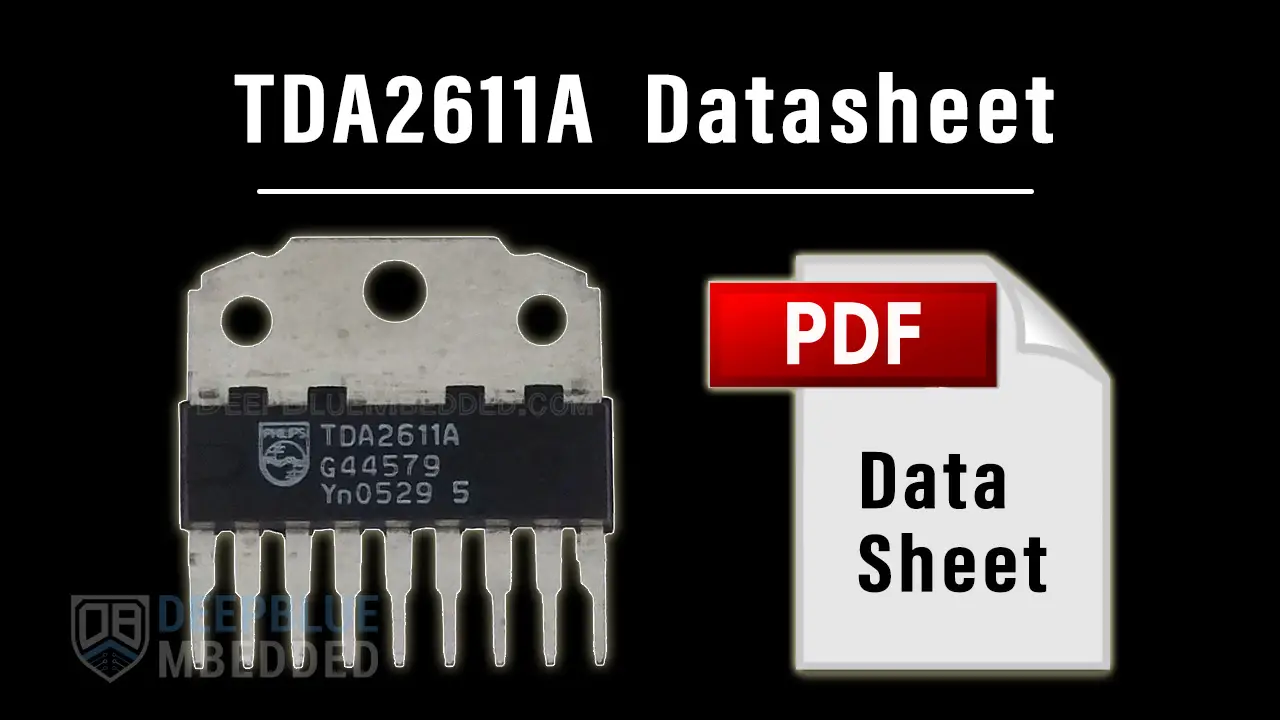
TDA2611A Datasheet PDF Download
There are two manufacturers who are sharing the datasheet of the TDA2611A online. Namely, NXP (Philips, formerly) and UTC. You can download the TDA2611A datasheet pdf file using the link below.
TDA2611A Equivalent / Alternative ICs
To find an equivalent/alternative IC for the TDA2611A, it needs to have the following requirements:
- VCC Range: 6v To 35v (or more)
- Output Power: 4.5W (or more)
By applying the above specs to the filtering system on mouser.com, I could easily find more than 5 alternative ICs to the TDA2611A. You can check it yourself here and select your desired specs.
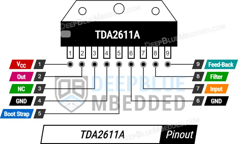
TDA2611A Pinout Diagram
Here is the TDA2611A pinout diagram.

Typical Applications & Use Cases
- TV Audio Amplifier
- Car Audio Amplifier
- Musical Instruments
- HMI Applications
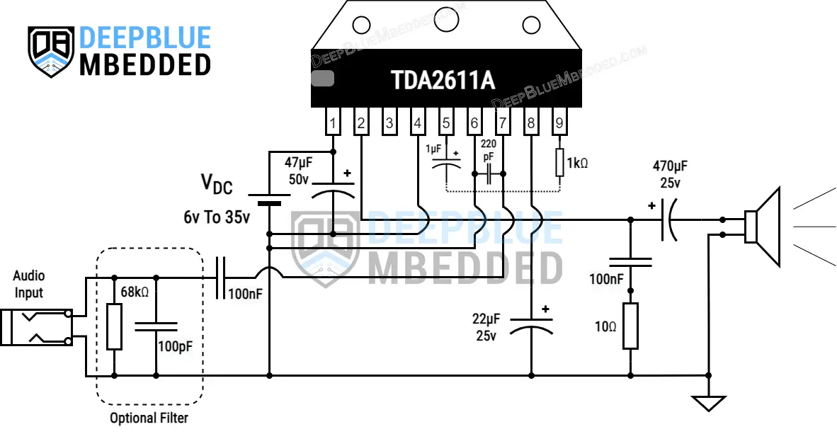
TDA2611A Circuit Diagram (5W Audio Amplifier)
This is the Audio Amplifier Circuit Diagram That I’ve implemented based on the information found in the TDA2611A datasheet. I’ve just added an additional (optional) input filtering for RFI protection.

For more information about building this circuit diagram shown above and how to test it practically, check the project article in the next section below.
More TDA2611A Circuit Schematics & Projects
Here are some more projects based on the TDA2611A audio amplifier IC that will give more in-depth information about designing audio power amplifiers. As well as some other Audio Power Amplifier ICs that are worth checking out.
Wrap Up
This was a quick round-up for the TDA2611A audio power amplifier IC that overviews its features, pinout, and application circuit diagram example project. As well as how to test it & find suitable equivalent alternative ICs for replacement. If you find this helpful, you’d definitely need to check out our other Audio Amplifier ICs articles.


