
This project is a 5W Audio Amplifier based on the TDA2611A IC. We’ll discuss the fundamental elements of audio power amplifier circuit design based on the TDA2611A, and how to test it in practice. You’ll learn how to properly set up & test the TDA2611A audio amplifier circuit in this project.
Table of Contents
- TDA2611A 5W Audio Amplifier IC
- TDA2611A Audio Amplifier Circuit Schematic Diagram
- More TDA2611A Circuits & Audio Projects
- Wrap Up
TDA2611A 5W Audio Amplifier IC
The TDA2611A is a 5W mono Audio Power Amplifier IC. It’s got a wide input supply voltage range (6v to 35v) and a typical output power of 4.5W to 5W. Below is the pinout diagram for the TDA2611A IC.

You can check the TDA2611A Datasheet for more specifications information and a typical application circuit.
Typical Applications & Use Cases:
- TV Audio Amplifier
- Car Audio Amplifier
- Musical Instruments
- HMI Applications
TDA2611A Audio Amplifier Circuit Schematic Diagram
This is the Audio Amplifier Circuit Diagram That I’ve implemented based on the information found in the TDA2611A datasheet. I’ve just added an additional (optional) input filtering for RFI protection.
Required Components
| QTY. | Component Name | Buy |
| 1 | TDA2611A | Amazon.com |
| 1 | Resistors Kit | Amazon.com |
| 1 | Capacitors Kit | Amazon.com |
| 1 | Input Audio Jack | Amazon.com |
| 1 | Audio Aux Cable | Amazon.com |
| 1 | Test Speaker | Amazon.com |
| 1 | BreadBoard | Amazon.com |
| 1 | Jumper Wire Kit | Amazon.com |
You can check this DeepBlueMbedded Storefront Page for a complete list of the test equipment that you’ll need to build your own electronics lab at home. No need to rush for these items, we typically get them one by one over the years.
Schematic Diagram

The 100nF input capacitor is preferred to be a ceramic capacitor (avoid electrolytic). Add the input RFI filter if needed, in case you’re hearing a static noise (hissing) while the amplifier is IDLE.
The speaker I’ve used in this project is a 5W/4Ω speaker. Across the speaker, you can see a (100nF + 10Ω) network that’s known as the “Zobel Network” which keeps the speaker load impedance constant across the operating frequency range.
Wiring Diagram
Here is the wire-up for the TDA2611A audio power amplifier on a breadboard.

TDA2611A Amplifier Testing
The testing setup that I’ve used for this project is shown below.

To measure the output power, I’ve used a dummy load instead of a speaker to avoid generating excessive noise in my lab room and also to protect my speaker if something goes wrong during the test. The function generator is used to generate a fixed tone (1kHz sine wave) with controllable magnitude.
The output at the load is monitored on the oscilloscope screen. We’ll increase the input sine wave’s amplitude up to the point where the amplifier starts saturating and distorting the output waveform. This is the maximum output power that it can generate at that level of Vcc before it starts clipping.
I’ve repeated that test multiple times at different Vcc voltage levels to measure the maximum output power of the TDA2611A amplifier. I’ve managed to achieve the 5W characteristic power rating of the amplifier at a Vcc level of 15v. Here is a summary of the test results below.
The Audio Amplifier Output Power (Average Power) is calculated using the formula below:
Pout(Avg) = (VP)2 / 2(RL)
Where, VP is the peak output voltage, and RL is the load resistance.
| Test Case 1 | Test Case 2 |
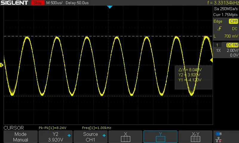 | 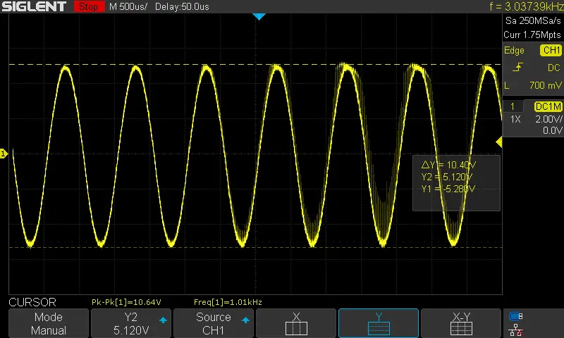 |
| Vcc = 9v Vp = 4v Output Power = (4)2/2(4Ω) = 2W | Vcc = 12v Vp = 5.2v Output Power = (5.2)2/2(4Ω) = 3.5W |
TDA2611A Audio Amplifier Demo
Here is a demo video for the TDA2611A audio power amplifier test using a 4Ω/5W speaker.
More TDA2611A Circuits & Audio Projects
More TDA2611A circuits and projects are linked below. There are more Audio Power Amplifier Projects here on our website if you’d like to check them out.
Wrap Up
This was a quick round-up for the TDA2611A audio power amplifier IC that overviews its features, pinout, and application circuit diagram example project. As well as how to test it & find suitable equivalent alternative ICs for replacement. If you find this helpful, you’d definitely need to check out our other Audio Projects articles.