I didn’t have the chance, or time, to share this old project from May 2018. It’s a PIC development board based on the PIC18F2550 microcontroller. This small PCB is amazing for quick prototyping of your projects or just to practice all the LABs while you’re learning from my Embedded Systems with Microchip PIC MCUs Course.
In this article, I’ll show you the features of this PIC development board PCB, how to order it, and get your boards fabricated at a very low cost. And how to assemble and solder it, then run your first blinking LED example firmware on it. Let’s get right into it.
[toc]
Board Features
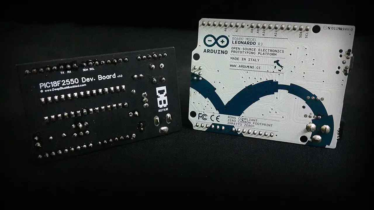
This board is much smaller than the well-known Arduino board (4cm x 6.5cm), yet it has very impressive features which are listed down below:
|
 |
Prototyping Sample Projects
This development board can be used alongside with all tutorials of my free embedded systems course to practice all LABs and projects much more easily. It does also reduce the time to set up all the necessary circuitry that you need to get started including power, oscillator, programming port, etc. Here are some example projects prototyping using this PIC18F development board.
1 LED Blinking on PIC Development Board
The first project is a very simple LED blinking example code running on the PIC18F2550 development board. Here is a short demo video showing the board in real life view.
2 Distance Meter With PIC Development Board
The next project is a simple distance meter using an ultrasonic sensor and an LCD with the PIC18F development board. You can check out the full tutorial (Distance Meter) for the explanation, schematics, and code listing. And here is the short demo video for the testing of this project.
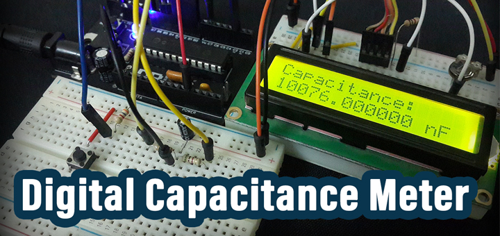
3 Digital Capacitance Meter
The next project is a digital capacitance meter using the PIC18F development board with an LCD to measure and display the capacitance of unknown capacitors. You can also check out the full tutorial (Capacitance Meter) for a complete explanation of the capacitance measurement technique, schematics, and code listing. And here are the final results for that project.
4 CapTouch Sensor With PIC Development Board
One last project to show off on this PIC development board is a capacitive touch button to switch ON/OFF an LED by implementing the CVD (Capacitive Voltage Divider) Technique on PIC18F2550 microcontroller. Here is the demo video for this project.
If you’re interested in the capacitive touch sensing application and would like to learn how to design CapTouch based embedded solutions, then you should grab your copy of ESM Issue1. It’s now on sale for only 1.99$ so don’t miss this out and check out the contents & reviews of the eBook to have a closer look at its scope.

Board Fabrication Steps @ JLCPCB
I’ve chosen to go with JLCPCB when I first designed this board and still highly recommend this service to anyone. It’s by far the best I’ve ever used in terms of quality, speed, and low cost. Its competitive price point makes it a market-leading company in this area. You can use this promo code “JLC-REBE” which is permanent (never expires) to get 2$ offer fabrication for your 5 boards.
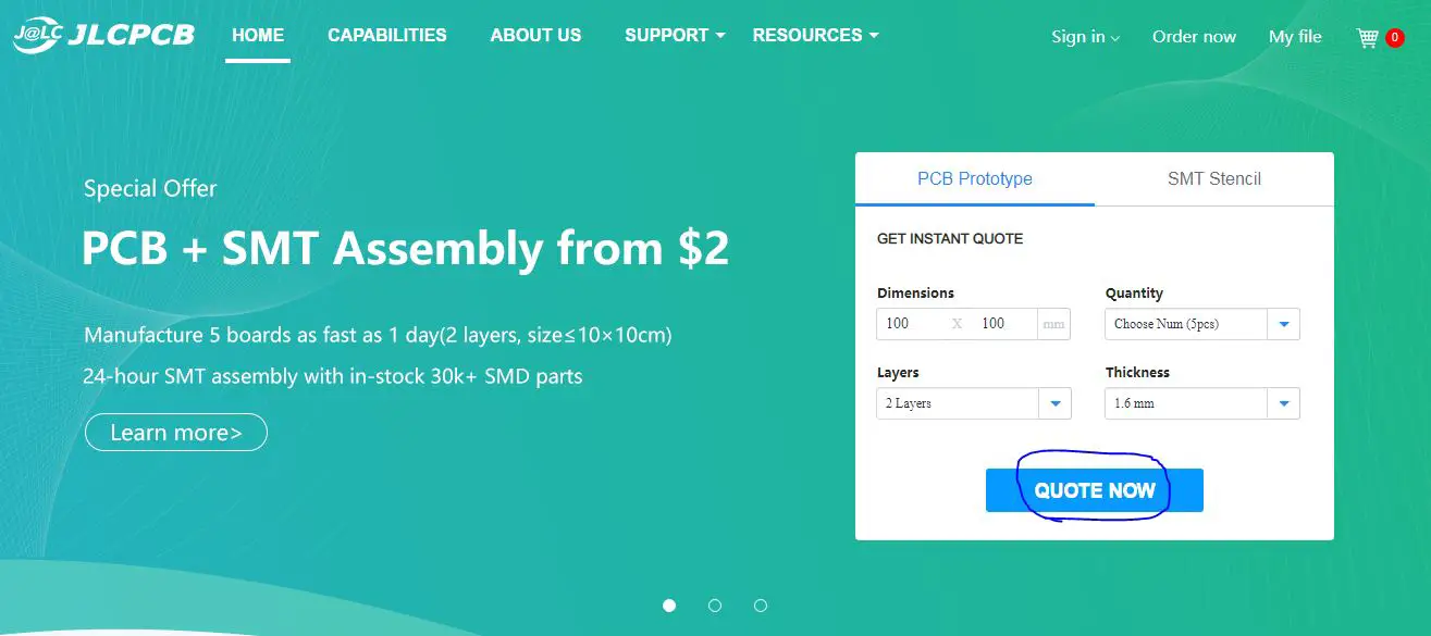
Step1: Go to JLCPCB.com & Click on “Quote Now”
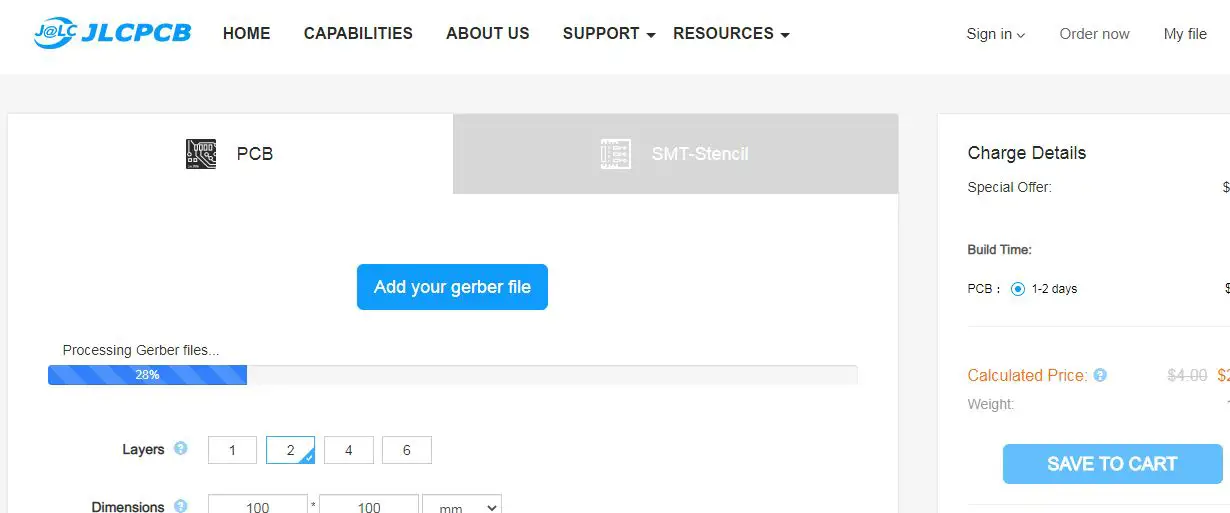
Step2: Upload the Gerber files to JLCPCB
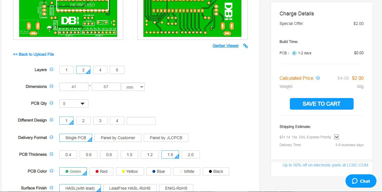
Step3: Choose the board color, fabrication options, and quantity
Step4: Place the order, Write Your Shipping Address, and Pay the due amount
Now, you’ll have to wait the turnaround time for JLCPCB fabrication which can be 24hours for standard options. And maybe up to 3 days in case you choose fancy options for your board like the matte black color finish which I absolutely love for all of my boards <3
PIC Development Board Soldering & Assembly
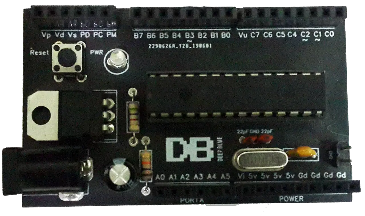
All the components you’ll need to are listed in the picture down below. This board is all THT components that are very easy to solder for beginners and require no skills at all. The board silkscreen layer includes the components’ names for easier identification while assembling it.
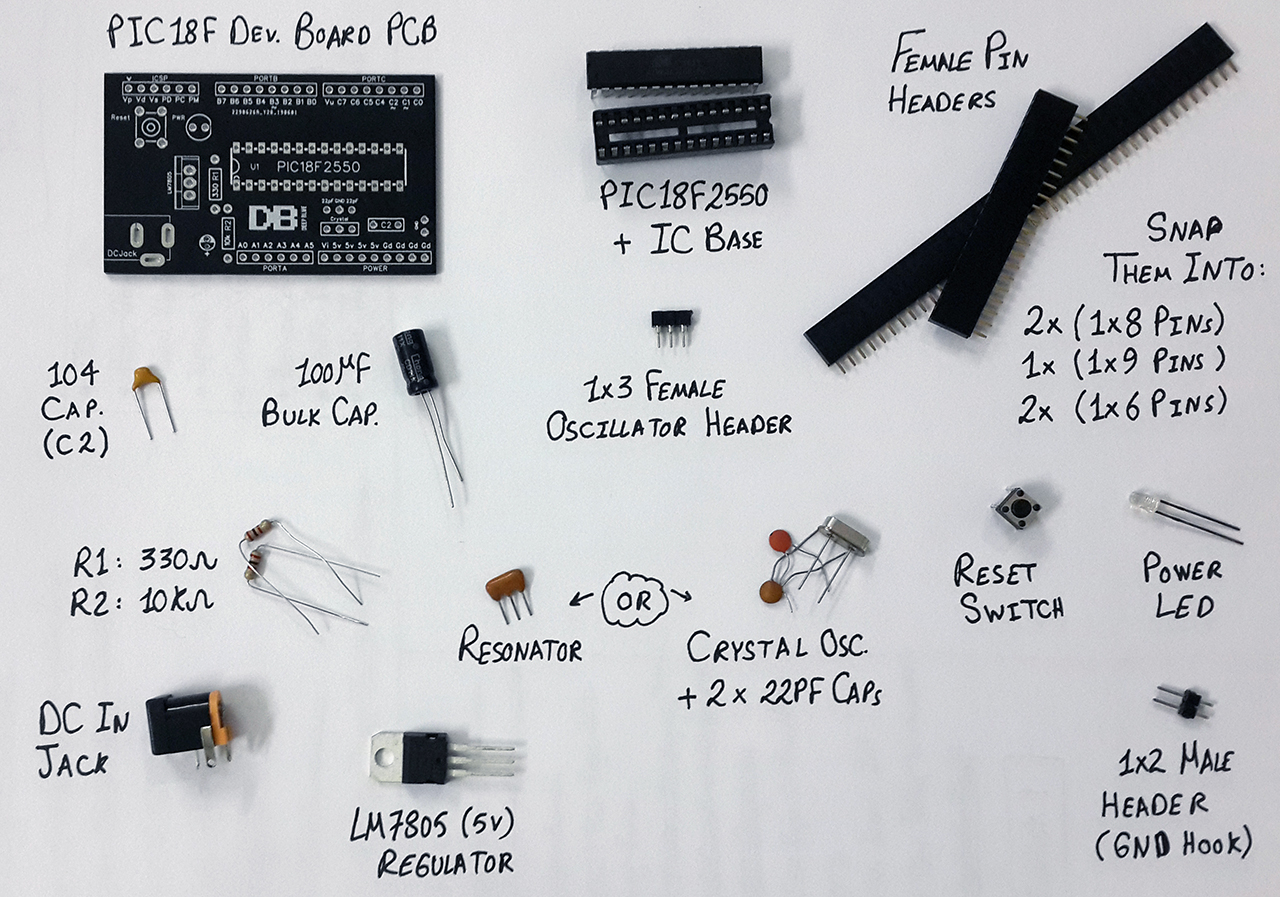
Now, you should have all these components around. Then, start snapping the female pin headers into the specified sizes for all ports on the board. The oscillator is not fixed you can change it however you want, or you can use the 3-pin resonator instead of a crystal as well.
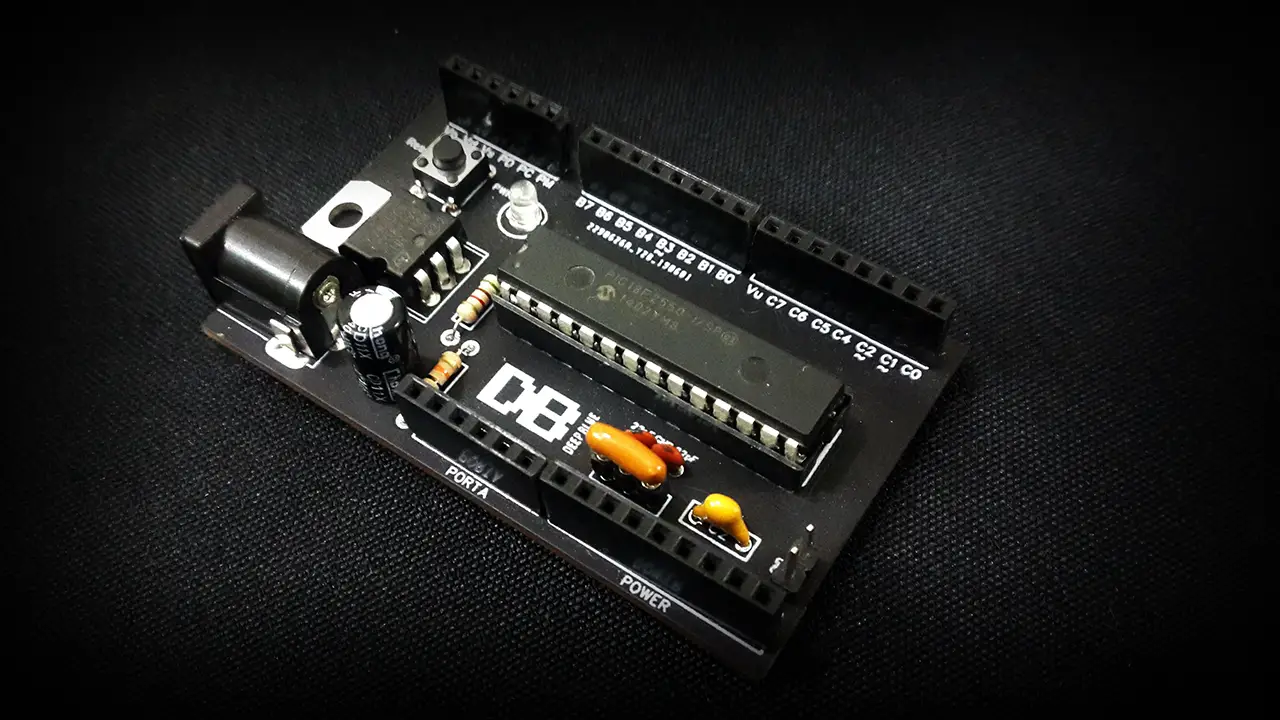
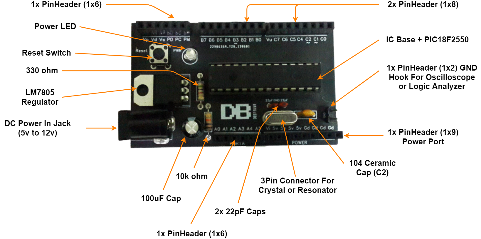
The next step is to start placing the THT components into the PCB board one by one and solder them in place using your iron and use the following image below as a reference for all parts on the board and the correct placement of each one.
And finally, we’ll be ready to do some tests and burn our first firmware example code on the PIC development board and see how if it works as expected or there is an issue in soldering to be solved.
Testing LED Blinking Example
After getting your copy of the board Gerber files from DeepBlue Shop, you’ll also find a demo example code in the same folder. Just for testing the board functionality after booting up for the first time. And it should be able to blink an LED as shown below.
Here is the code listing for the test example
|
1 2 3 4 5 6 7 8 9 10 11 12 13 |
void main(void) { TRISB = 0x00; PORTB = 0x00; while(1) { PORTB = 0xFF; __delay_ms(50); PORTB = 0x00; __delay_ms(50); } return; } |
And here is the demo video for testing
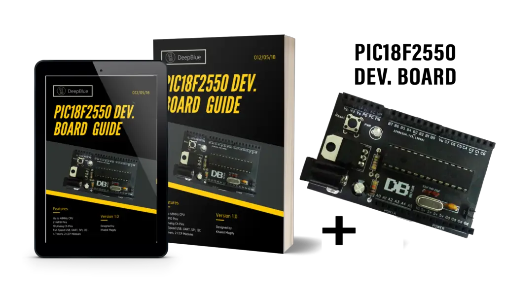
Get Your PIC Development Board Now!
If you’re interested in playing around with this board to ease prototyping your projects, check it out on DeepBlue Shop! it’s on sale right now for 50% discount, so don’t miss this out.
Don’t also forget to use this promo code for your orders from JLCPCB to get 2$ offer, it’s “JLC-REBE” and it’s permanent (doesn’t expire). Good luck with your projects!