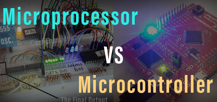
Microprocessor vs Microcontroller: Key Differences
Microprocessors and microcontrollers are two terms that are often used interchangeably. However, they have distinct differences that set them apart from one another. In this article, we will explore the differences between microprocessors and microcontrollers, and provide a comprehensive understanding of their individual functionalities with practical examples.
Microprocessors (MPUs):
A microprocessor unit (MPU) is a central processing unit (CPU) that is designed to process data and execute instructions. It is the heart of a computer system and is responsible for executing instructions that are stored in memory. A microprocessor is a single chip that contains an arithmetic logic unit (ALU), a control unit, and registers that hold internal CPU data. And most importantly, it doesn’t run on its own. It’s always part of a full computer system.
One of the key features of a microprocessor is its ability to process data at a high speed. It is designed to perform complex mathematical calculations and logical operations quickly and efficiently. Microprocessors are commonly used in personal computers, servers, and other computing devices.
Microcontrollers (MCUs):
A microcontroller unit (MCU) is a compact computer system that is designed to perform specific functions. It consists of a microprocessor, memory, and input/output (I/O) peripherals on a single chip. Unlike microprocessors, microcontrollers are designed for embedded systems and are used in a variety of applications such as automobiles, medical devices, and industrial control systems.
One of the key features of a microcontroller is its ability to control and monitor external devices. It is designed to interact with the environment and perform specific tasks based on inputs from sensors and other peripherals. Microcontrollers are commonly used in systems that require real-time operation and low power consumption.
[toc]
Types of Microprocessors & Microcontrollers
Here are some types of microprocessors & microcontrollers available in the market today.
Types of Microprocessors:
-
x86 Microprocessors: These microprocessors are based on the x86 architecture and are commonly used in personal computers and servers. Popular examples include Intel Pentium and AMD Ryzen processors.
-
ARM Microprocessors: These microprocessors are based on the ARM architecture and are commonly used in mobile devices and embedded systems. Popular examples include ARM Cortex-A and Cortex-M processors.
-
PowerPC Microprocessors: These microprocessors are based on the PowerPC architecture and are commonly used in embedded systems and high-performance computing. Popular examples include IBM PowerPC processors.
-
RISC-V Microprocessors: These microprocessors are based on the open-source RISC-V architecture and are gaining popularity in embedded systems and IoT applications.
Types of Microcontrollers:
-
8-bit Microcontrollers: These microcontrollers have an 8-bit architecture and are commonly used in simple embedded systems that require low power consumption and low cost.
-
16-bit Microcontrollers: These microcontrollers have a 16-bit architecture and are commonly used in more complex embedded systems that require higher performance and more memory.
-
32-bit Microcontrollers: These microcontrollers have a 32-bit architecture and are commonly used in high-performance embedded systems that require advanced features such as real-time processing, connectivity, and security.
-
ARM Cortex-M Microcontrollers: These microcontrollers are based on the ARM Cortex-M architecture and are commonly used in IoT applications, wearable devices, and industrial control systems.
-
PIC Microcontrollers: These microcontrollers are produced by Microchip Technology and are commonly used in automotive, industrial, and consumer applications.
-
AVR Microcontrollers: These microcontrollers are produced by Atmel and are commonly used in consumer electronics, automotive, and industrial applications.
-
MSP Microcontrollers: These microcontrollers are produced by Texas Instruments and are commonly used in industrial control systems, medical devices, and automotive applications.
- And much more…
Features of Microprocessors & Microcontrollers
Here are some features for both microprocessors and microcontrollers that set each device apart from the other.
Features of Microprocessors:
-
General-purpose: Microprocessors are designed to execute a wide range of general-purpose computing tasks, including arithmetic operations, logical operations, data manipulation, and control flow.
-
Complex instruction set architecture (CISC): Microprocessors typically have a large instruction set that supports complex operations, making them suitable for high-level programming languages.
-
High clock speed: Microprocessors are typically designed to operate at high clock speeds, ranging from a few hundred megahertz to several gigahertz, to achieve high performance.
-
Multiple execution units: Microprocessors typically have multiple execution units, such as arithmetic logic units (ALUs) and floating-point units (FPUs), to perform multiple operations simultaneously.
-
External memory: Microprocessors rely on external memory to store data and instructions, which can be accessed through a memory bus.
-
Operating system support: Microprocessors typically run on operating systems, such as Windows, macOS, and Linux, that provide a rich set of software libraries and tools for software development.
Features of Microcontrollers:
-
Embedded systems: Microcontrollers are optimized for embedded systems that have specific requirements, such as real-time processing, low power consumption, and small form factor.
-
Reduced instruction set architecture (RISC): Microcontrollers typically have a reduced instruction set that supports basic operations, making them suitable for low-level programming languages.
-
Low clock speed: Microcontrollers are typically designed to operate at low clock speeds, ranging from a few kilohertz to a few hundred megahertz, to conserve power.
-
Single execution unit: Microcontrollers typically have a single execution unit, such as an ALU, to perform one operation at a time.
-
On-chip memory: Microcontrollers have on-chip memory, including flash memory for storing instructions and data, and SRAM for storing data during runtime.
-
No operating system support: Microcontrollers do not typically run on operating systems and instead rely on low-level programming languages, such as assembly and C, for software development.
Microprocessors VS Microcontrollers
Here are the summarized differences between Microprocessor VS Microcontroller.
| Feature | Microprocessors | Microcontrollers |
|---|---|---|
| Processing power | High | Low |
| Additional features | Limited | Widely Available |
| Memory | Typically requires external memory for storage | On-chip memory |
| Cost | Expensive | Cost-effective |
| Application | General purpose, used in computers, servers, and high-end electronics | Specific tasks, used in embedded systems such as medical devices, consumer electronics, and industrial control systems |
| Power consumption | High | Low |
| Processing speed | High | Low |
| Interrupt handling | Can handle multiple interrupts simultaneously, but requires additional circuitry | Handles interrupts quickly and efficiently, typically without additional circuitry |
| Ease of use | Requires more complex programming and system design | Requires less complex programming and system design |
| Size | Typically larger | Typically smaller |
| I/O interface | Usually has a separate I/O interface | On-chip I/O interface |
| Real-time processing | Not designed for real-time processing | Designed for real-time processing |
| Number of peripherals | Fewer | More |
| Architecture | Von Neumann or Harvard architecture | Harvard architecture |
| Instruction set | Wide variety of instructions | Limited instruction set, often specific to a particular task |
| Debugging | Complex debugging process | Easier debugging process |
Differences Between Microprocessors & Microcontrollers
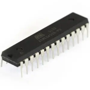
Nobody can tell whether a miscellaneous DIP chip is a microcontroller or a microprocessor by just observing how it looks. The key distinguishing parameter is its functionality, and that’s what we’re going to briefly describe hereafter.
Microcontrollers
A Microcontroller, is a complete and fully-functioning computer on a single chip.
A typical microcontroller has a CPU, RAM, ROM, Peripherals (Counters/Timers, Comparators, ADC, DC, DMA, etc), and IO Ports all on the same IC chip. The majority of modern MCUs, nowadays, come with internal oscillators which means, you can flash your code and hook up the DC power source, et voila! Everything is up and running!
Microcontrollers range on the (Low-end To High-end) spectrum. Therefore, the price is proportional to the total performance and capabilities of each device. The most common factors we pay attention to while choosing a microcontroller are as follows
- Max CPU Frequency
- Memory Size (RAM)
- Bus Width (8-Bit, 16-Bit, 32-Bit)
- IO Pins Count
- ADC (#Channels & SamplingRate)
- DMA Channels
- Serial Ports (UART, SPI, I2C, USB, I2S, CAN)
- Other Peripherals (Timers, IRQ Pins, etc)
The more advanced peripherals a microcontroller has, the more you pay per unit. And the price is also proportional to the CPU performance (in DMIPS). For some applications, especially battery-powered devices, power consumption is the number1 one factor being considered, so it really depends.
There are many families that include a tremendous amount of microcontroller devices ranging from small 8-Bit tiny ones (may cost 20 cents per unit) up to 32-Bit ARM cores and DSPs. The most common ones are (8051, AVR, PIC for 8-Bit, and ARM-based MCUs for 32-Bit devices).
Microprocessors
A Microprocessor is a bare CPU on chip.
A typical microprocessor has a punch of pins coming out of the IC package which represents a CPU unit. These pins should connect to buses (Data and Address) and some of them are control signals that should be also connected to the correct logic circuits on your system’s board.
As you can see, a typical microprocessor chip can do nothing on its own. Just like the processor of your PC, can you have it running out of the motherboard? it just can’t as it has not been designed to operate as a standalone computer system, unlike the microcontroller.
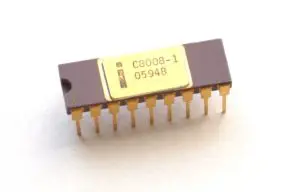
Intel has released the first microprocessor chip ever back in the early 70s which was the 4-Bit intel 4004 MPU (Microprocessor Unit). And it has been in continuous development for these microprocessors. Small microprocessors have been widely used in microcontroller design. While high-performance microprocessors have evolved to form our modern PCs’ processors.
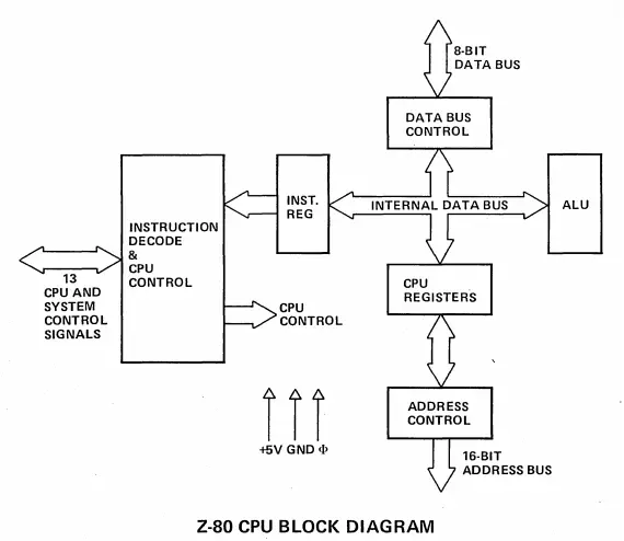
The internal structure of a microprocessor chip includes the following: ALU unit, Buses Control (Data & Address), CPU Registers, Instructions Decode & Control Unit, etc as found in any CPU across the globe.
Remarkable examples of early MPUs (Microprocessors) include: Motorola 6800, Zilog Z80, Ti TMS1000, Intel 8080, IBM 801.
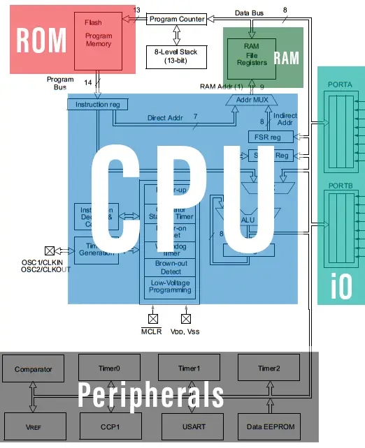
Computers Vs Microcontrollers
Last but not least, we’ll compare a typical microcontroller to a typical personal computer in terms of the internal components which happen to be the same. As we’ve stated earlier, a microcontroller is a complete computer on a single chip. Hence, a microcontroller has all the fundamental components of a common computer but with much fewer resources. Have a look at the following infographic illustration
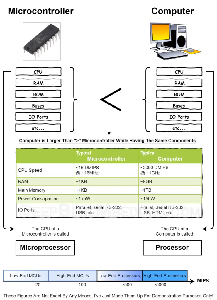
As you might have noticed, a microcontroller has nearly the same components of a large computer but in a very limited amount for each resource of them. The CPU unit of your PC is a high-performance Processor. Whereas, the CPU unit of a small microcontroller is a Microprocessor.
At the end of the infographic, there is an imaginary performance spectrum with non-exact figures. Just to illustrate how microprocessors range in performance. Therefore, the target application, its price, and performance change as well.
Applications of Microprocessors:
Microprocessors are widely used in computing devices such as personal computers, servers, and mobile devices. They are also used in other applications such as military systems, industrial control systems, and telecommunications equipment.
- In the industrial sector, microprocessors are used in programmable logic controllers (PLCs) to control and monitor production processes. They are also used in power management systems and building automation systems.
- In the telecommunications industry, microprocessors are used in routers, switches, and modems to manage network traffic and facilitate communication between devices.
- In the military sector, microprocessors are used to do computational intensive tasks besides some FPGA accelerators to achieve real-time constraints in tracking and guidance tasks.
Applications of Microcontrollers:
Microcontrollers are used in a variety of embedded systems such as medical devices, consumer electronics, and industrial control systems. They are designed to perform specific functions and are optimized for low power consumption.
- In the medical industry, microcontrollers are used in devices such as insulin pumps, pacemakers, and blood glucose monitors. They are also used in diagnostic equipment such as ultrasound machines and X-ray machines.
- In the consumer electronics industry, microcontrollers are used in devices such as remote controls, thermostats, and smart home devices. They are also used in toys and gaming consoles.
- In the industrial sector, microcontrollers are used in motor control systems, robotics, and environmental monitoring systems.
- In the Automotive industry, microcontrollers are used in vehicle sub-systems or electronic control units (ECUs) and internal networking. From door window control & wipers to engine control, airbags, monitoring, diagnostics, and more.
- In IoT and smart wearables, microcontrollers are used to do simple computation tasks, human-machine interfaces (HMI), and battery management for extended periods of operation by running in low-power modes
Microcontroller VS Microprocessor: Example1 (MCU)
A microcontroller unit (MCU) has everything it needs in order to run user-written instructions (Code). And perform any sort of data manipulations, IO operations, or peripherals control. It has been a standard “Hello World!” example in embedded systems to have an “LED Blinking” up and running on your target microcontroller device.
In this section, we’ll blink an LED using a Microcontroller (From Ti)
- Microcontroller: TM4C123G (ARM Cortex M4)
- IDE: Ti CCS (Code Composer Studio)
- Development Board: Tiva C Launchpad
The c-code mentioned below was compiled on CCS and uploaded to the Tiva C board using the USB debugger. The ARM microcontroller has everything it needs to run the code which toggles an io pin that is connected to the onboard LED on the Tiva C board. Here is the code listing which we’ll be testing
|
1 2 3 4 5 6 7 8 9 10 11 12 13 14 15 16 17 18 |
#include <stdbool.h> #include <stdint.h> #include "tm4c123gh6pm.h" void PortF_Init(void); void delay_ms(uint32_t); int main(void) { PortF_Init(); // Initialize The LED IO Pin (Output) while(1) { GPIO_PORTF_DATA_R |= 0x04; // (Turn LED ON) delay_ms(100); // Wait 100ms GPIO_PORTF_DATA_R &= ~(0x04); // (Turn LED OFF) delay_ms(100); // Wait 100ms } } |
Here is the final output for our test code (For The ARM Microcontroller)
Microcontroller VS Microprocessor: Example2 (MPU)
On the other hand, a microprocessor unit (MPU) can’t do anything useful on its own. We’ve to build a complete computer system around it in order to develop any sort of application. In this experiment, we’ll build an 8-LED shifting animation by sending 1’s to the IO port (which we’ll also have to build using registers).
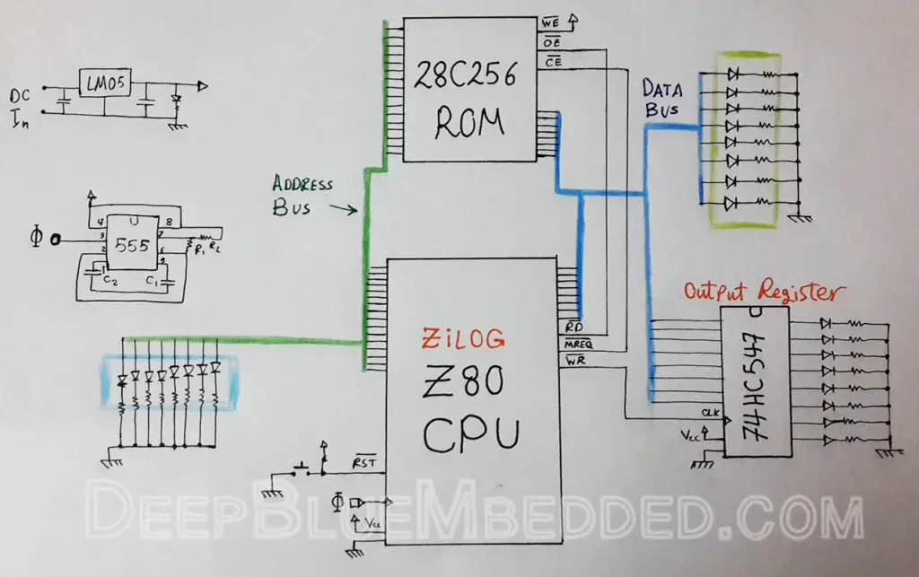
In this section, we’ll develop our project using a Microprocessor (From Zilog)
- Microprocessor: Zilog Z80
- ROM: AT28C256 Parallel EEPROM
- RAM: NO
- IO: 8-Bit Output Register (74HC574)
- Buses: (Address & Data) = Punch of wires + LEDs XD
- Clock Source: Custom 555-Timer Oscillator
- Power: Regulated 5v DC
First of all, we have to connect all those components together. If you’re interested, here is the general schematic diagram for this test circuit.
After connecting everything up…
Here is the assembly code that I’ve written for this example. You should also notice, that you’ll have to convert this code into 0’s and 1’s and write them byte-by-byte in the ROM memory chip on your own. And, yes, this may be tough sometimes!
|
1 2 3 4 5 |
LDA, 1 Loop: OUT (255), A RLC A JR Loop |
Using the datasheet of the Z80 microprocessor, it’s a kind of straightforward process to convert the code above into binary code (0’s & 1’s) and write it to our ROM memory. You can get a proper EEPROM programmer on eBay or build a microcontroller-based programmer with an Arduino maybe or do it in the hard way with some DIP switches!
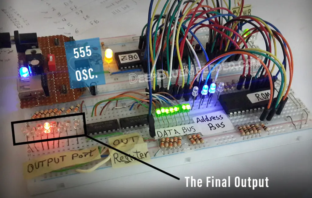
Here is the final output for our test code (For The Z80 Microprocessor)
 |
Conclusion
A Microcontroller is a small computer on a single chip. That you can program to do any tasks you want. They are typically used for control systems, home automation, robotics, avionics, telecommunication, and everywhere else you may think of!
A Microprocessor is a CPU on a chip that can’t do anything on its own. You can build a proper computer system around any given microprocessor to have it perform any instructions (code) you want to. However, it may be more difficult to build a small control system using a bare microprocessor. Yet it’s not a cost-efficient way to go. It only pays off if you’re building a complete motherboard consisting of a microprocessor unit with some memory, buses, and peripherals. Which we can see in the personal computers market and the like.
You can learn microprocessor programming for both the fun of it, and to understand how assembly instructions run on the low level inside a CPU. This skill may not be marketable or much profitable nowadays, but it contributes to making you more knowledgeable about the internals of computer systems hardware & software as well.
To Learn More About Microcontrollers Programming, You Can Start With One of The Following (FREE) Courses!
- PIC Microcontrollers Programming Tutorials
- STM32 ARM-Based Microcontrollers Course
- ESP32 Microcontrollers Tutorials
FAQ & Answers
The main difference between a microprocessor and a microcontroller is that a microprocessor is a general-purpose computing device that requires external memory and peripherals to function, while a microcontroller is a specialized computing device that combines a processor, memory, and input/output peripherals on a single chip. Microcontrollers are optimized for embedded systems that have specific requirements, such as real-time processing, low power consumption, and small form factor.
It depends on the specific requirements of the application. Microcontrollers are better suited for embedded systems that require real-time processing, low power consumption, and a small form factor. Microprocessors are better suited for general-purpose computing tasks, such as running an operating system or executing complex algorithms.
Examples of microcontrollers include the Atmel AVR, Microchip PIC, and Texas Instruments MSP microcontrollers. Examples of microprocessors include the Intel Pentium, AMD Ryzen, and ARM Cortex-A microprocessors.
Arduino is a microcontroller board that uses an Atmel AVR microcontroller as its processing unit. The Arduino board also includes input/output peripherals, such as analog-to-digital converters, digital input/output pins, and serial communication interfaces, making it a complete embedded system development platform.
The Raspberry Pi is a single-board computer that uses an ARM-based microprocessor as its processing unit. The Raspberry Pi also includes input/output peripherals, such as USB ports, HDMI ports, and GPIO pins, making it a complete computing system. While the Raspberry Pi can be used for embedded systems applications, it is not a microcontroller as it does not have the same level of real-time processing and low-power consumption optimizations as microcontrollers.

Do you have a neat, formal schematic for this? I noticed you have on output chip on the schematic and two on the photo. ???