In this project article, I’ll be showing you an interesting project of mine that I wanted to share for quite a long time. It’s a capacitive touch piano project, specifically version 1 of it. It’s designed to be a practical example that shows you how to design an embedded system that incorporates capacitive touch sensors and DDS sound synthesis.
It’s not meant to be “the best piano” in the world. However, it should sound cool and ultimately help you learn some new concepts and techniques. Without further ado, let’s get started!
| This project is sponsored by JLCPCB. One of the market-leading PCB manufacturing services in the entire world with extremely competitive prices starting from 2$/5boards. And a very high-quality PCB fabrication as we’ll see at the end of this project while testing our board. |
[toc]
Project Overview
This project is designed to be 2 versions project. In the first version (v1) of the project, which is this one, we’ll be focusing on the design of the front-end for the CapTouch Piano. Doing the capacitive touch sensors design, scanning, filtering, and all that stuff. And the sound synthesis part will be off-loaded to a PC software with a serial port communication channel in between.
After testing the front-end behavior of the (v1) board, we can confidently incorporate that part into the (v2) board which will have everything on the same board. The piano will have the CapTouch sensing for all buttons, digitally-filtered, then it’ll do the DDS sound synthesis, and finally the audio power amplifier circuitry to output audible sound to speakers port. So you can plug power “or battery” and play!
Scope of CapTouch Piano v1 Project
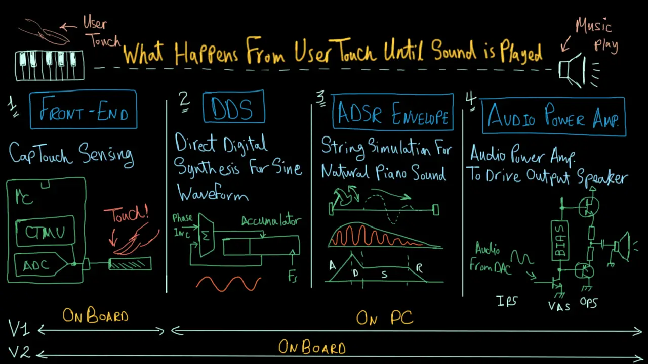
As you can see in the diagram above, the first version (v1) of this project is going to have only the front-end on the PCB board. Which is the capacitive touch piano buttons as well as the microcontroller part that will be scanning through those buttons and filtering-out any noise.
And it should finally send the key states’ data to a PC software that will be handling all other stages. The PC software in (v1) project is going to do the DDS, waveform shaping, and driving the output speaker from your PC soundcard and play the actual music.
Short Demo Test Video
Features Summary For This Bord
Here is a list of the most important features of this project board and also the accompanying firmware code.
 17 CapTouch Piano Keys
- Customizable/Programmable Notes For Each Key
- Reliable Digitally-Filtered Key Scanning Routine
- Relatively Small Size Board With Low Count BOM
- +5v DC input For Normal Operation
- UART Port For PC Communication
- ICSP Port For Flashing Firmware
- Power Indicator LED
- Aux LED For Debugging
- 4 Mounting Holes For External Housing (non-metallic)
System Requirements & Design Specs.
In this section, we’ll wrap up everything that needs to be designed in order to achieve this project’s goals. Starting with the hardware (PCB), then the microcontroller’s firmware, and finally the PC software that plays the sound.
Hardware Requirements
- The Board Shall Be Powered From +5v Adapter
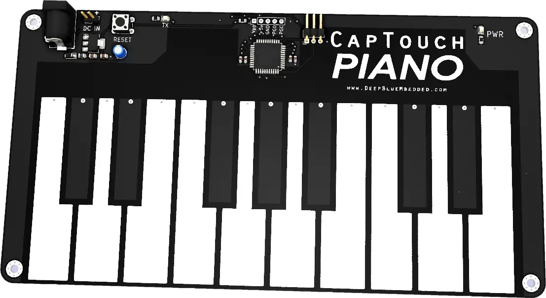
- The Board Shall Have 17 CapTouch Keys Piano-Shaped
- The PCB Shall Have a Power Indicator LED
- The PCB Shall Have a Programming pin-header port
- The PCB Shall Have a UART serial pin-header port
- The PCB Shall Have an AUX LED For Debugging
Firmware Requirements
- The Main uC Shall Scan All 17 CapTouch Keys (at least @ 50Hz)
- The Main uC Shall Digitally-Filter All Readings
- The Main uC Must detect key hold/release states
- The Main uC Shall Send Key States Via UART (@ 115200bps)
Software Requirements
- The PC Software Shall Open Serial Port (USB-TTL)
- The PC Software Shall Always Scan For New Character Received
- If new char is received, the software shall trigger (Pluck) the DDS with the appropriate frequency that corresponds to the piano note being played
- Visualize the sound waves being played on the screen window
Hardware Design
Detailed step-by-step design for this project will be done in a pretty long video that I’m going to published very soon on my English youtube channel. Make sure to subscribe there so you don’t miss that out when it’s published, And I’m also going to published a handful of tutorials as requested by many readers and it’s time to go on YouTube as well. Stay tuned for this!
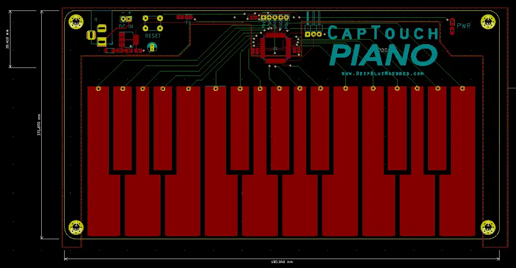
Schematic Design & Capture
The first step in the PCB design is to finalize the schematic design of the board and then do the schematic capture to the CAD software tool. The PCB design tool that I’ve used for this project was KiCAD.
PCB Layout Editing & Routing
Generating Fab.-Ready Output Files (Gerber)
The final step is to generate the fabrication-ready output files (Gerber) to be sent later for manufacturing.
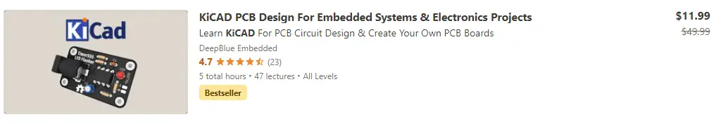
If you’re interested in PCB design with KiCAD, you can check my course on Udemy! it’s on SALE and you can get it for maybe 10$ or something. And in case you can’t enroll for whatever reason, just join my email list to get a 100% FREE coupon whenever I’ve free coupons, I’ll send them to all my list subscribers. So it can be something to consider.
PCB / SMT Order @ JLCPCB
I’ve chosen to go with JLCPCB when I first designed this board and still highly recommend this service to anyone. It’s by far the best I’ve ever used in terms of quality, speed, and low cost. Its competitive price point makes it a market-leading company in this area.
You can use this promo code “JLC-REBE” which is permanent (never expires) to get a 2$ offer fabrication for your 5 boards.
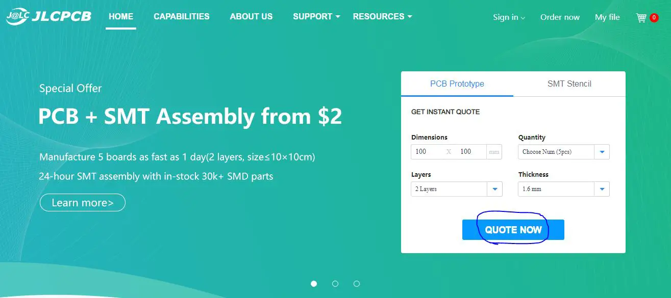
Step1: Go to JLCPCB.com & Click on “Quote Now”
Step2: Upload the Gerber (zipped) file to JLCPCB
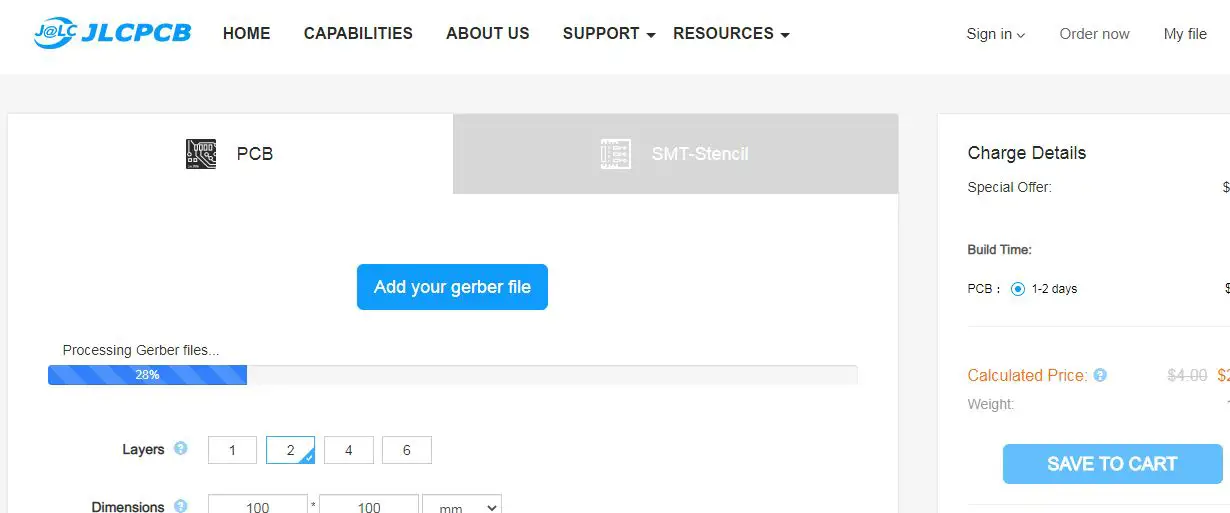
Step3: Choose the board color, fabrication options, and quantity
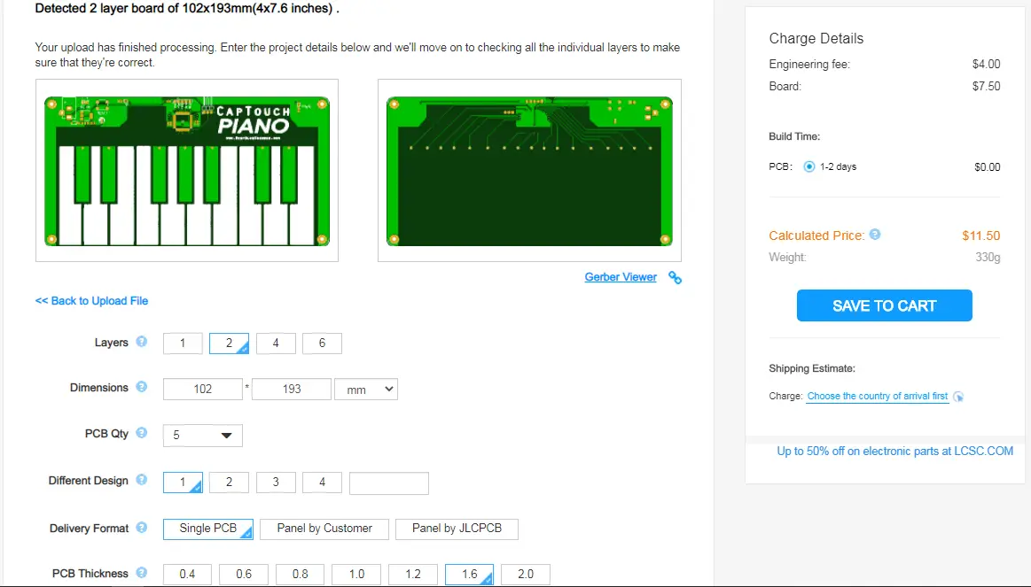
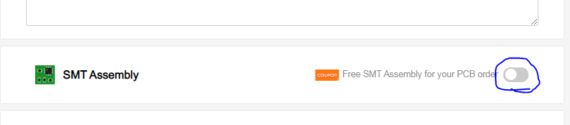
Step4: Scroll Down & Enable SMT Assembly For This Order
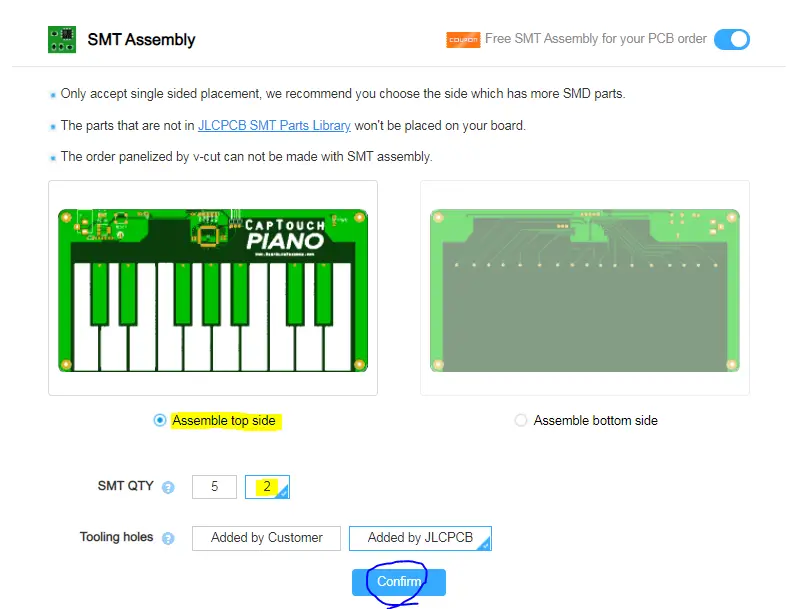
Step5: Choose The Following SMT Options: 2 Boards / Top Side SMT
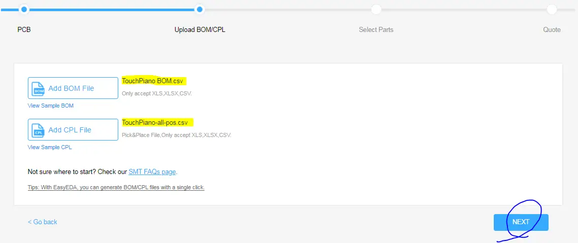
Step6: Now, You’ll Be Prompted To Upload The SMT Files “BOM & POS”. Which I’ve Provided To You in The SMT Assembly Folder. Click The Buttons & Upload Them!
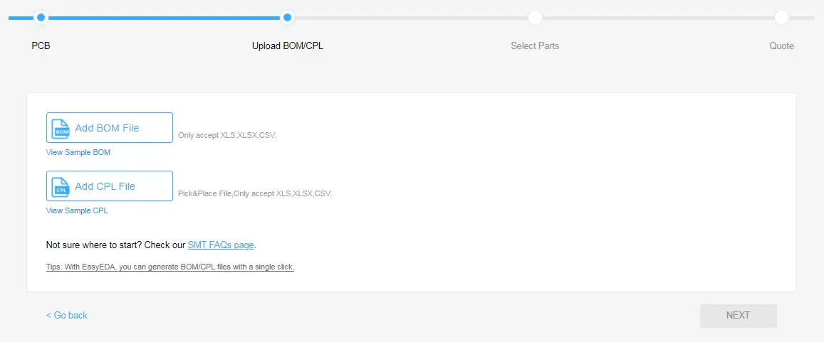
Step7: Uploading Done .. Click Next
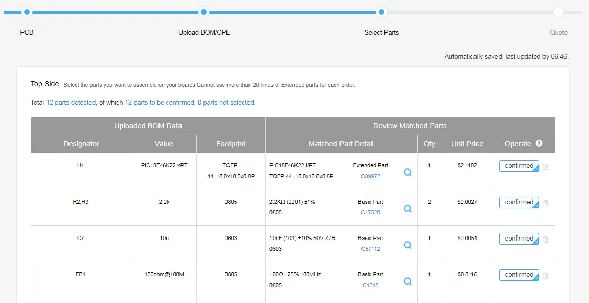
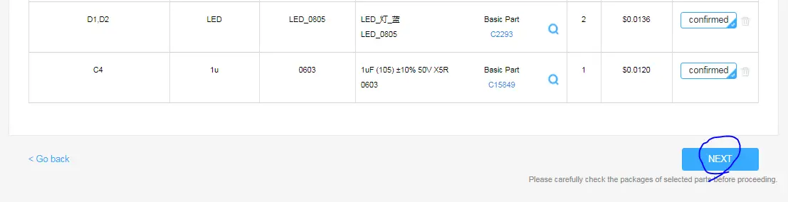
Step8: Parts Automatically Detected By JLCPCB System .. Click Next
Step9: Parts Placement Preview. Now We’re Done! Place Your Order!
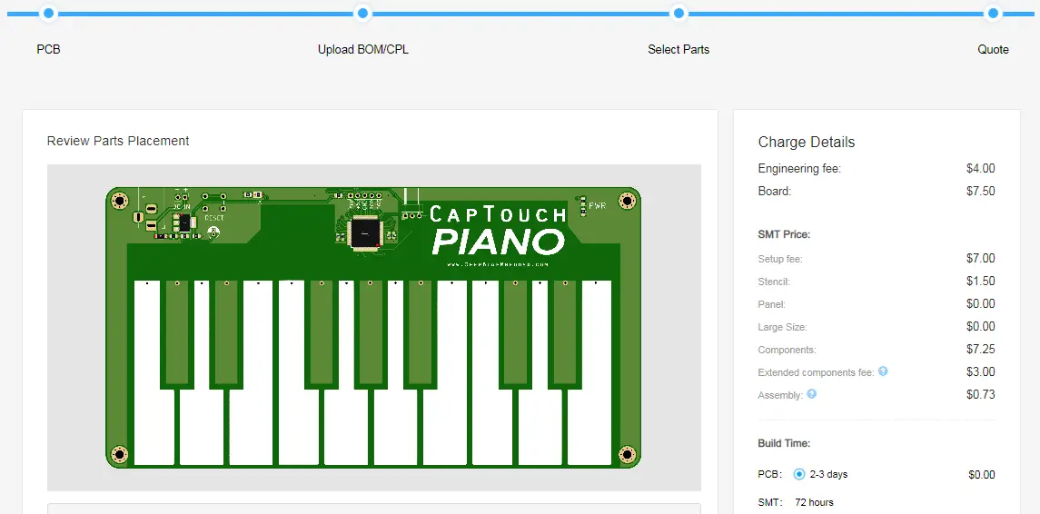
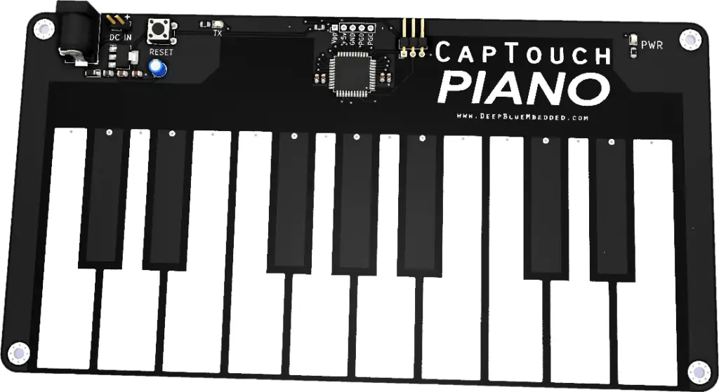
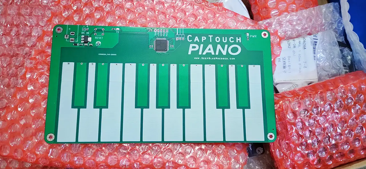
That was the last step for placing the SMT order at JLCPCB.com, just give them a couple of days and your boards will be delivered to you. And here is how it looked like when it arrived to me.
Now, we’re almost done with the hardware part of this project. So let’s move to the next part which is developing the firmware for the main microcontroller (PIC18F46K22).
Firmware Layered Architecture
After being done with the top-level design and hardware, we can now proceed to the firmware design step. Starting with the software layered architecture overview “Static Design”. In which, we decide on the required software components and the layers in the whole project.
As you can see in the figure below, there are only two layers in this simple architecture. The top “Application Layer” in which we’ll develop the target application. And the MCAL layer (Microcontroller Abstraction Layer) which includes all the hardware peripherals drivers (libraries) which directly interacts with the low-level hardware registers of the machine.
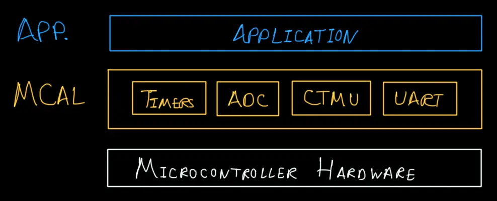
The MCAL layer includes the following drivers for the respective purposes:
- Timers: can be used to periodically scan the piano keys
- ADC: used in conjunction with the CTMU to do the Capacitive Touch Sensing
- CTMU: Used with ADC to do the Capacitive Touch Sensing
- UART: used to send out the piano key states to PC
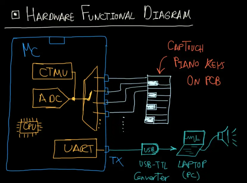
The Complete Hardware Functional Diagram
To conclude everything, here is a full functional diagram for this project. So you can better imagine how each part interacts with other system components. Because now we’re going to shift the focus to the last part of this system which is the PC software (audio synthesis).
Software Part (PC Sound Synthesis)
As we’ve stated earlier that the audio synthesis will be done on the PC side. Therefore, we need to also develop a software program that reads in the incoming serial data from the uC on the PCB and generates the corresponding tone sound that matches the note to be played.
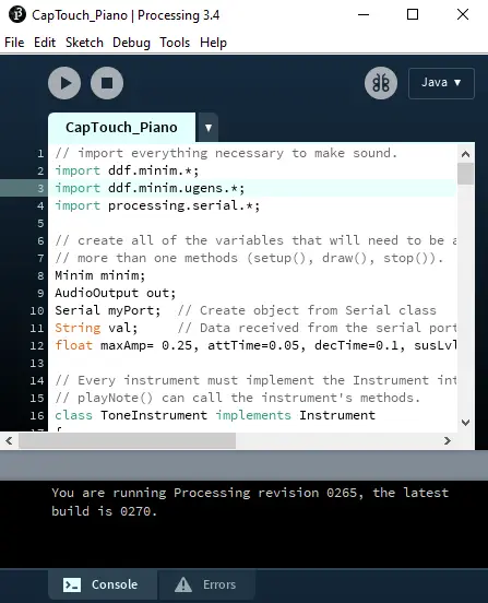
For this task, I’ve chosen to go for a processing library that will help us handle the ADSR sound synthesis as well as serial data reading. So, you need to first get processing downloaded on your machine.
visit processing.org
download and install the software package. And open it, you’ll notice that it looks very similar to Arduino IDE.
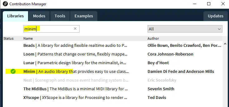
Now, you’ll need to install the audio library that I’m using in my code which is “Minim”. Just like you install Arduino library as usual. Go to the library manager tab and search for the “Minim” audio library and click install, then you’re good to go!
Now, create a new sketch and use the code listing down below.
Just make sure that you change the “COM” port number to match the one for your USB-TTL chip. And you can play with the ADSR “Attack-Decay-Sustain-Release” values in order to change how the piano will sound.
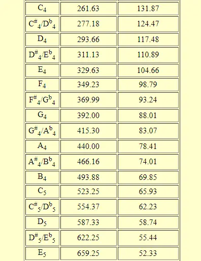
You can add more notes if you wish or change the octave. I’m using octave 4 and switched to octave 5 which sounds better to me. And here is the frequency table that you should be using for finding out the fundamental frequency for each note.
PC Audio Synth Software For Piano (java)
|
1 2 3 4 5 6 7 8 9 10 11 12 13 14 15 16 17 18 19 20 21 22 23 24 25 26 27 28 29 30 31 32 33 34 35 36 37 38 39 40 41 42 43 44 45 46 47 48 49 50 51 52 53 54 55 56 57 58 59 60 61 62 63 64 65 66 67 68 69 70 71 72 73 74 75 76 77 78 79 80 81 82 83 84 85 86 87 88 89 90 91 92 93 94 95 96 97 98 99 100 101 102 103 104 105 106 107 108 109 110 111 112 113 114 115 116 117 118 119 120 121 122 123 124 125 126 127 128 129 130 131 132 133 134 135 136 137 138 139 140 141 142 143 144 145 146 147 148 149 150 151 152 153 154 155 156 157 158 159 160 161 162 163 164 165 166 167 168 169 170 171 172 173 174 175 176 177 178 179 180 181 |
// import everything necessary to make sound. import ddf.minim.*; import ddf.minim.ugens.*; import processing.serial.*; // create all of the variables that will need to be accessed in // more than one methods (setup(), draw(), stop()). Minim minim; AudioOutput out; Serial myPort; // Create object from Serial class String val; // Data received from the serial port float maxAmp= 0.25, attTime=0.05, decTime=0.1, susLvl = 0.1, relTime = 0.1; // Every instrument must implement the Instrument interface so // playNote() can call the instrument's methods. class ToneInstrument implements Instrument { // create all variables that must be used througout the class Oscil sineOsc; ADSR adsr; // constructor for this instrument ToneInstrument( float frequency, float amplitude ) { // create new instances of any UGen objects as necessary sineOsc = new Oscil( frequency, amplitude, Waves.SINE ); //Constructor for an ADSR envelope with maximum amplitude, attack Time, decay time, sustain level, //and release time. Amplitude before and after the envelope is set to 0. adsr = new ADSR( maxAmp, attTime, decTime, susLvl, relTime ); // patch everything together up to the final output sineOsc.patch( adsr ); } // every instrument must have a noteOn( float ) method void noteOn( float dur ) { // turn on the ADSR adsr.noteOn(); // patch to the output adsr.patch( out ); } // every instrument must have a noteOff() method void noteOff() { // tell the ADSR to unpatch after the release is finished adsr.unpatchAfterRelease( out ); // call the noteOff adsr.noteOff(); } } // setup is run once at the beginning void setup() { String portName = "COM5"; //Change COM5 to the port number that your USB-TTL is connected myPort = new Serial(this, portName, 115200); // initialize the drawing window size( 512, 200, P2D ); // initialize the minim and out objects minim = new Minim( this ); out = minim.getLineOut( Minim.MONO, 2048 ); } // draw is run many times void draw() { float Amplitude = 1.5; float duration = attTime + decTime + susLvl + relTime; // erase the window to black background( 0 ); // draw using a white stroke stroke( 255 ); // draw the waveforms for( int i = 0; i < out.bufferSize() - 1; i++ ) { // find the x position of each buffer value float x1 = map( i, 0, out.bufferSize(), 0, width ); float x2 = map( i+1, 0, out.bufferSize(), 0, width ); // draw a line from one buffer position to the next for both channels line( x1, 50 + out.left.get(i)*50, x2, 50 + out.left.get(i+1)*50); line( x1, 150 + out.right.get(i)*50, x2, 150 + out.right.get(i+1)*50); } if ( myPort.available() > 0 ) { // If data is available, val = myPort.readStringUntil('\n'); if(val!=null) { //out.pauseNotes(); if(val.charAt(0)=='a') { out.playNote( 0.0, duration, new ToneInstrument( 261.63, Amplitude ) ); //out.resumeNotes(); } if(val.charAt(0)=='b') { out.playNote( 0.0, duration, new ToneInstrument( 277.18, Amplitude ) ); //out.resumeNotes(); } if(val.charAt(0)=='c') { out.playNote( 0.0, duration, new ToneInstrument( 293.66, Amplitude ) ); //out.resumeNotes(); } if(val.charAt(0)=='d') { out.playNote( 0.0, duration, new ToneInstrument( 311.13, Amplitude ) ); //out.resumeNotes(); } if(val.charAt(0)=='e') { out.playNote( 0.0, duration, new ToneInstrument( 329.63, Amplitude ) ); //out.resumeNotes(); } if(val.charAt(0)=='f') { out.playNote( 0.0, duration, new ToneInstrument( 349.23, Amplitude ) ); //out.resumeNotes(); } if(val.charAt(0)=='g') { out.playNote( 0.0, duration, new ToneInstrument( 369.99, Amplitude ) ); //out.resumeNotes(); } if(val.charAt(0)=='h') { out.playNote( 0.0, duration, new ToneInstrument( 392, Amplitude ) ); //out.resumeNotes(); } if(val.charAt(0)=='i') { out.playNote( 0.0, duration, new ToneInstrument( 554.37, Amplitude ) ); //out.resumeNotes(); } if(val.charAt(0)=='j') { out.playNote( 0.0, duration, new ToneInstrument( 587.33, Amplitude ) ); //out.resumeNotes(); } if(val.charAt(0)=='k') { out.playNote( 0.0, duration, new ToneInstrument( 523.25, Amplitude ) ); //out.resumeNotes(); } if(val.charAt(0)=='l') { out.playNote( 0.0, duration, new ToneInstrument( 622.25, Amplitude ) ); //out.resumeNotes(); } if(val.charAt(0)=='m') { out.playNote( 0.0, duration, new ToneInstrument( 493.88, Amplitude ) ); //out.resumeNotes(); } if(val.charAt(0)=='n') { out.playNote( 0.0, duration, new ToneInstrument( 659.25, Amplitude ) ); //out.resumeNotes(); } if(val.charAt(0)=='o') { out.playNote( 0.0, duration, new ToneInstrument( 415.3, Amplitude ) ); //out.resumeNotes(); } if(val.charAt(0)=='p') { out.playNote( 0.0, duration, new ToneInstrument( 440, Amplitude ) ); //out.resumeNotes(); } if(val.charAt(0)=='q') { out.playNote( 0.0, duration, new ToneInstrument( 466.16, Amplitude ) ); //out.resumeNotes(); } } } } |
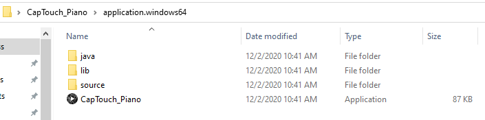
You can export the application after getting to a point where everything is working fine for you. The COM port is fixed, and the ADSR values are better optimized for your personal preference. Then it can be turned into a permanent application that runs on any machine by a click of a button to export the app.
Final Hardware Testing
Here is a demo video for this project. Disclaimer: I’m not a good piano player by any means XD! I did learn a bit when I was young and haven’t played for years.
Concluding Remarks
✓ Get All Source Files For This Project!
✓ This project will be explained in a more detailed tutorial video that I’m going to publish on my new YouTube channel. So make sure you subscribe there so that you don’t miss any new tutorial videos. Any suggestions will be welcomed!
✓ If you’ve got any further questions or need help in a project you can drop me a comment down below or contact me via emails. I’ll do my best to help as much as I can.
✓ If you feel like really into PCB design and making your own boards. Please, check out my course on PCB Design For Embedded Systems. It’s growing in popularity and has been on the “Highest Rated” on Udemy since published. So, check it out!
✓ In case you find this website helpful, please consider supporting my work on patreon. I’d really like to grow that campaign in order to be able to take down a lot of the random google ads scattered all over my website. I don’t really like it as much as most of the readers. But with +50k readers/month there are only 3 partons, it’s quite difficult maybe.
I am very happy to see your articles again and very proud to be one of the first followers of your new channel