| Previous Tutorial | Tutorial 9 | Next Tutorial | |||||
| Timer Modules In PIC Microcontrollers | |||||||
| PIC Microcontrollers Course Home Page ???? | |||||||
In this tutorial, you’ll learn everything about PIC Timers modules, How do they work? What are their modes of operation, and applications? You’ll also learn how to operate the timer modules within the Microchip PIC microcontrollers. At the end of this tutorial, we’ll generate time delays using the Timer1 module instead of using delays. This will be a really long read, but absolutely fun and fundamentally informative! Let’s get started.
[toc]
Components Needed for this tutorial
| Quantity | Component Name |
| 1 | PIC16F877A |
| 1 | Breadboard |
| 1 | Jumper Wires Pack |
| 1 | 330Ω Resistors |
| 1 | 4MHz Crystal OSCillator |
| 1 | LM7805 Voltage Regulator |
| 1 | 9v Battery or any Power Supply Source |
| 1 | PICkit3 (PIC Programmer) |
Introduction To PIC Timer Modules
You can hardly find an embedded system application that solves real-life problems which do not utilize timers in one way or another. Timer modules are substantially fundamental in embedded systems development. You just can’t work around specific tasks/problem when it’s the timers’ job. They are irreplaceable by any means of software tricks and algorithms. Not like some other hardware peripherals that may possibly be simulated/implemented in software by “Bit-Banging” GPIO (general purpose I/O) pins.
Digital Counters
A timer module is typically a digital circuit (peripheral) within the microcontroller chip that could be controlled via few dedicated registers SRFs. The core of this digital circuitry is referred to as “digital counter” in the computer engineering literature. A digital counter is a series of flip-flops serially connected to construct the so-called digital counter.
Let’s consider the JK-Flip-Flop at first. It’s a digital circuit whose behavior follows the following truth table. And It’s symbolically drawn as shown down below
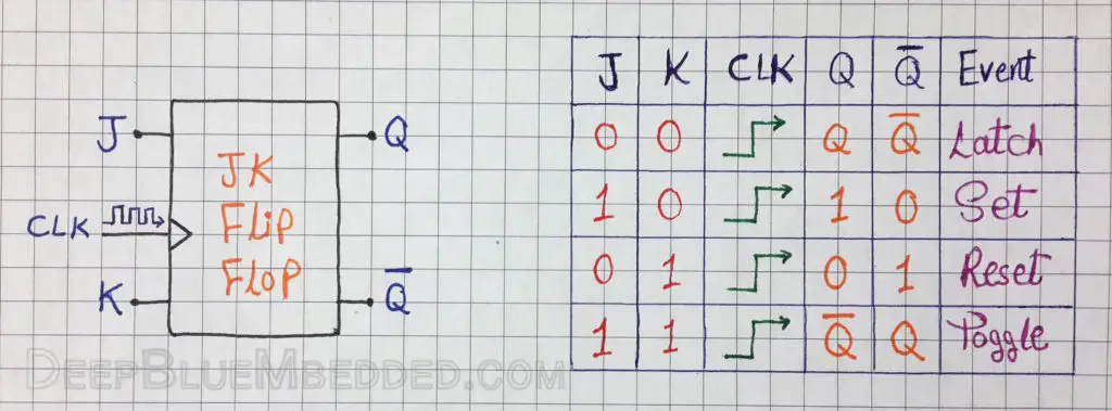
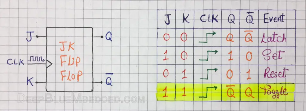
For the sake of the abstraction level we’re following, let’s set aside what’s inside a flip-flop and why it has the above truth table. Let’s consider it as a discrete element and focus more on its role in the big picture of the digital counter. Also for simplicity, let’s consider the 4th state of operation for the JK-Flip-Flop.
Which means that if both J & K pins are set (High or 1), then every clock (rising-edge) will toggle the state of the Q pin.
Well, if we’ve used the Q pin from a flip-flop as a clock source for another (serially connected) flip-flop, Then the 2nd Q pin will be toggling at a frequency that is half of the base clock frequency being fed to the first flip-flop. So if we’ve connected a 3rd flip-flop and used the 2nd Q pin as a clock source for it, its Q pin should be toggling at a 1/4 of the base frequency and so on. The resulting circuit of these 3-Flip-Flops is called 3-Bit Digital Counter.
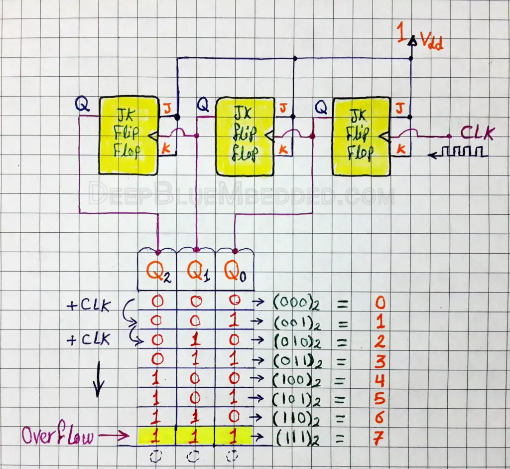
As you may have noticed in the diagram shown above. The Q0 is toggling at the same input frequency (once/1-clock). Q1 is toggling at 1/2 of the base frequency (once/2-clocks). Q2 is toggling at 1/4 of the base frequency (once/4-clocks).
The interesting fact about this result is that the bit-pattern of (Q2 Q1 Q0)2 is actually the binary representation of the numbers from (0 to 7)! Well, a digital circuit that outputs the bit-pattern of the counting numbers (0 to N) is called a digital counter!
Timer OverFlow
A point to notice in the previous example is the state where the 3-outputs (Q2 Q1 Q0) are all 1’s (1 1 1)2 which is 7
This state is called the OverFlow state! it’s typically followed by (0 0 0) and the counter starts again from (0 to 7).
Timer Resolution
Another point to consider here is the value at which OverFlow occurs. It was 7 in the previous example and that’s because the counter circuit was a 3-Bit counter. Which essentially means it’ll be counting from (0) to (1-2n) as (n is the number of bits).
Hence, a 3-Bit timer will count from (0 to 7). An 8-Bit timer will count from (0 to 255). A 16-Bit timer will count from (0 to 65535). And so on
This feature (capacity) of timer modules is called Resolution. Which is the number of bits that form the whole timer module
How do PIC Timer Modules Work?
You may have noticed in the previous section that I’ve referred to the digital counter as timer module and vice versa. In fact, I’ve done so in order to make you touch and feel the strong relationship between timer modules and digital counters.
The truth is a Timer module is more than a digital counter. The digital counter is the core part in the circuitry of a timer module but there are also a few logic gates and registers hooked in such a way to provide programmable control over the operation of the core digital counter.
For instance, there is a pre-scaler circuitry to divide the frequency of the input clock by fixed ratios (e.g. 1:1, 1:2, 1:4, 1:8, 1:16, …etc). There is also a MUX (multiplexer) to switch between the two possible clock sources (local clock or external clock). Which obviously determines the timer’s mode of operation.
Modes of operation
Timer modules could be configured to operate in two different modes
- Timer Mode
- Counter Mode
PIC Timer Mode
In timer mode, the PIC timer module is being incremented by the local clock of the system (oscillator). As you know, the oscillator’s frequency is constant it may be 4,8,16,20MHz or whatever value. Hence, the value stored in the timer module’s flip-flops represents the number of Ticks. Which can easily be converted to time period using the formula below
Time period = Number Of Ticks x Period of Each Tick
Thus, the timer module in timer mode can be used as a stopwatch! Which means It can be used in such a way that generates time intervals that separate between desired events. And it can also be used in such a way to measure the time period between a couple of events.
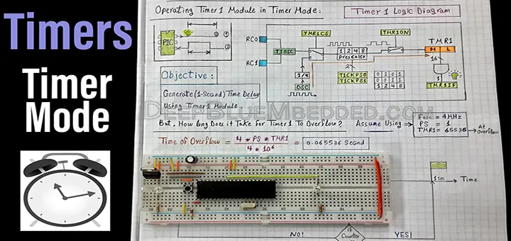
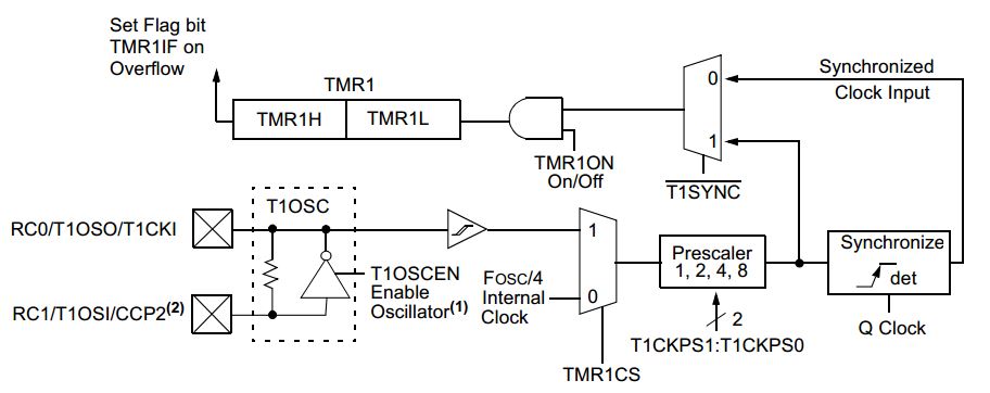
The block diagram of the Timer1 module (from the datasheet) is shown below
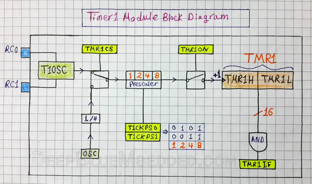
Here is another (simpler) way of representing the same block diagram
PIC Counter Mode
In counter mode, the PIC timer module is being incremented by an external clock source (signal) on the RC0 Pin. Which means if you’ve connected a push button to the counter’s external clock input, then pressing the button will increment the counter’s value (the TMRx register itself), it could be TMR0, TMR1, etc. The counter must first have a falling edge before increments occur on every rising edge.
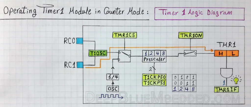 |
| In Counter Mode, The Timer1 Module Is Being Incremented By The External T1CK Pin |
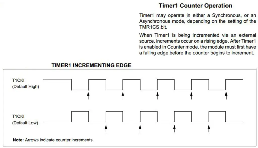 |
| In Counter Mode, The Timer1 Module Must First Have A Falling Edge Before Starting To Increment On Every Rising Edge |
As you might have noticed that the timer module generally has the core digital counter/register called TMRx. Where x could be 1,2 or whatever. And the other parts of the circuitry are controlled via a register called TxCON. Let’s consider Timer1 for instance. The SFR dedicated to controlling this Timer1 module is T1CON. In the next sub-section, we’ll discuss the functionality each bit of this register in detail.
T1CON Register
| T1CON | |||||||||
| R/W | R/W | R/W | R/W | R/W | R/W | R/W | R/W | ||
| – | – | T1CKPS1 | T1CKPS0 | T1OSCEN | T1SYNC | TMR1CS | TMR1ON | ||
| Bit 7 | Bit 6 | Bit 5 | Bit 4 | Bit 3 | Bit 2 | Bit 1 | Bit 0 | ||
| #Bit | Name | Set/Clear | Function Description | ||||||
| 0 | TMR1ON | 1 | Enables Timer1 | ||||||
| 0 | Stops Timer1 | ||||||||
| 1 | TMR1CS | 1 | External clock from pin RC0/T1OSO/T1CKI (on the rising edge) | ||||||
| 0 | Internal clock (FOSC/4) | ||||||||
| 2 | T1SYNC | 1 | When TMR1CS = 1, Do not synchronize external clock input
When TMR1CS = 0, This bit is ignored |
||||||
| 0 | When TMR1CS = 1, Synchronize external clock input
When TMR1CS = 0, This bit is ignored |
||||||||
| 3 | T1OSCEN | 1 | Oscillator is enabled | ||||||
| 0 | Oscillator is shut-off (the oscillator inverter is turned off to eliminate power drain) | ||||||||
| 4-5 | T1CKPS0:T1CKPS1 | 1 1 | 1:8 prescale value | ||||||
| 1 0 | 1:4 prescale value | ||||||||
| 0 1 | 1:2 prescale value | ||||||||
| 0 0 | 1:1 prescale value | ||||||||
| 6 | – | – | – | ||||||
| – | – | ||||||||
| 7 | – | – | – | ||||||
| – | – | ||||||||
Applications For PIC Timers / Counters
Timer modules are usually used for time measurement and time interval generation purposes. This is typically done by operating the PIC timer modules in timer mode. This means that operating the timer module in timer mode will enable you of
- Measuring time intervals (between a couple of events)
- Generating time intervals (between a couple of events)
The timer modules can also be used to count pulses from external sources (e.g. buttons, sensors, …etc). This is typically done by operating the timer modules in counter mode.
You should notice that we can easily implement a software counter by polling an I/O pin and incrementing a counter variable in memory. It’d be a better idea to use a specific IRQ pin instead of polling. However, you should not be overloading the hardware nor the software as long as you can take advantage of the hardware counter available on your chip!
Timers In PIC Microcontrollers
The PIC Microcontroller chip which we’re mostly using for this series of tutorials (PIC16F877A) has 3 different timer modules. They are listed down below
- Timer0
- Timer1
- Timer2
Each one of these timer modules has some specifications/featured that we’ll mention hereafter. However, the principle of operation is typically the same for any timer module within any microcontroller chip! That’s why we’ll only use Timer1 in the following LAB. Adjusting the code for situation-dependent applications should not be that kind of a big deal if you’ve already managed to grasp the broad concepts behind Timer Modules, and write your first driver c-code for it.
Timer0
According to the PIC16F877A datasheet, The Timer0 module (timer/counter) has the following features:
• 8-bit timer/counter
• Readable and writable
• 3-bit software programmable prescaler (8-options)
• Internal or external clock select
• Interrupt on overflow from FFh to 00h
• Edge select for external clock
The Timer0 module’s core register is TMR0 which is an 8-Bit SFR register.
Obviously, the 8-Bit resolution of this timer module essentially means that it’s capable of counting from 0 to 255. This means the PIC Timer0 module’s general equation is therefore
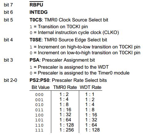
The control register for Timer0 is called OPTION_REG which is one of the core SRFs. Here is the brief functionality of each bit in this register.
| OPTION_REG | |||||||||
| R/W | R/W | R/W | R/W | R/W | R/W | R/W | R/W | ||
| RBPU | INTEDG | T0CS | T0SE | PSA | PS2 | PS1 | PS0 | ||
| Bit 7 | Bit 6 | Bit 5 | Bit 4 | Bit 3 | Bit 2 | Bit 1 | Bit 0 | ||
The block diagram for Timer0 Module (From the datasheet page 53) is shown below
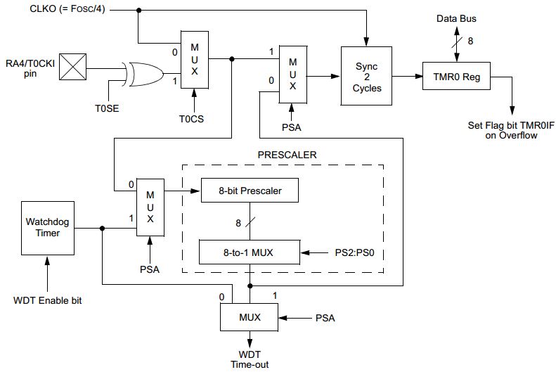 |
| Timer0 Block Diagram (Datasheet Page 53) |
You should have noticed that the prescaler for Timer0 module is shared with the WatchDog Timer (WDT). This means that you can only assign this hardware resource for only one of those timers. The PSA bit is responsible for assigning the prescaler circuitry.
Timer1
According to the PIC16F877A datasheet, The Timer1 module (timer/counter) has the following features:
• 16-bit timer/counter
• Readable and writable
• 2-bit software programmable prescaler (4-options)
• Internal or external clock select
• Interrupt on overflow from FFFFh to 00h
• Edge select for external clock
The Timer1 module’s core register is TMR1 which is a couple of 8-Bit SFR registers (TMR1L & TMR1H).
Obviously, the 16-Bit resolution of this timer module essentially means that it’s capable of counting from 0 to 65535. This means the PIC Timer1 module’s general equation is therefore
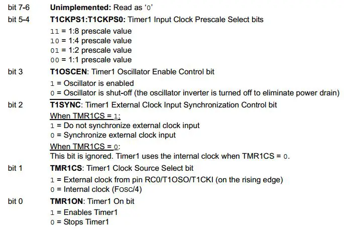
The control register for Timer1 is called T1CON. Here is the brief functionality of each bit in this register.
| T1CON | |||||||||
| R/W | R/W | R/W | R/W | R/W | R/W | R/W | R/W | ||
| – | – | T1CKPS1 | T1CKPS0 | T1OSCEN | T1SYNC | TMR1CS | TMR1ON | ||
| Bit 7 | Bit 6 | Bit 5 | Bit 4 | Bit 3 | Bit 2 | Bit 1 | Bit 0 | ||
The Block diagram for the Timer1 module is as mentioned earlier
|
| Timer1 Block Diagram (Datasheet Page 58) |
Timer2
According to the PIC16F877A datasheet, The Timer2 module (timer/counter) has the following features:
• 8-bit timer/counter
• Readable and writable
• 2-bit software programmable prescaler (3-options)
• 4-bit software programmable postscaler (16-options)
• Internal or external clock select
• Interrupt on overflow from FFh to 00h
• Edge select for external clock
The Timer2 module’s core register is TMR2 which is an 8-Bit SFR register.
The Timer2 module has an 8-bit period register, PR2. Timer2 increments from 00h until it matches PR2 and then resets to 00h on the next increment cycle. PR2 is a readable and writable register. The PR2 register is initialized to FFh upon Reset.
Obviously, the 8-Bit resolution of this timer module essentially means that it’s capable of counting from 0 to 255. This means the PIC Timer2 module’s general equation is therefore
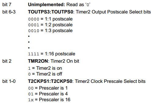
The control register for Timer2 is called T2CON. Here is the brief functionality of each bit in this register.
| T2CON | |||||||||
| R/W | R/W | R/W | R/W | R/W | R/W | R/W | R/W | ||
| – | TOUTPS3 | TOUTPS2 | TOUTPS1 | TOUTPS0 | TMR2ON | T2CKPS1 | T2CKPS0 | ||
| Bit 7 | Bit 6 | Bit 5 | Bit 4 | Bit 3 | Bit 2 | Bit 1 | Bit 0 | ||
 The Block diagram for the Timer2 module (From the datasheet page 61) is shown below
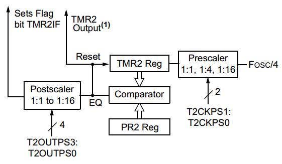 |
| Timer1 Block Diagram (Datasheet Page 61) |
Wrap-Up
- The main functionality is commonly shared between all timers in all microcontrollers
- Our main objective in this series of tutorials is to get a very good understanding of all the core modules within a typical microcontroller
- Dedicating 3 consecutive tutorials for each of Timer0, 1, and 2 may not provide as much value at this point as it seems to be. However, I’ll consider discussing each of them in the future.
- Timer0 has a shared PS with the WDT, and Timer2 is the hardware resource used for PWM modules.
For these reasons, we’ll be discussing only the PIC Timer1 module in detail and developing a driver firmware in order to operate it in both modes!
Using PIC Timer To Generate Time Delays
Step 1 – PIC Timer Module Configuration
The first step for generating time intervals (e.g. as delays) is to configure the timer module to operate in timer mode. You’ll also have to choose a value for the prescaler ratio even if you’re not willing to divide the input clock frequency. Just clear the prescaler select bits. These configurations are done by writing the c-code shown below
|
1 2 3 4 5 6 7 8 9 10 11 12 13 |
// -- [[ Configure Timer1 To Operate In Timer Mode ]] -- // Clear The Timer1 Register. To start counting from 0 TMR1 = 0; // Choose the local clock source (timer mode) TMR1CS = 0; // Choose the desired prescaler ratio (1:1) T1CKPS0 = 0; T1CKPS1 = 0; // Put Your Fist Event Here * Event 1 * // Switch ON Timer1 Module! TMR1ON = 1; |
After switching the Timer1 module ON, the timer will start incrementing once per instruction cycle. Which means the time of each Tick is calculated as follows
Tick Time = 1 / (Fosc/4)
Assuming that our MCU is running @ 4MHz => Tick time = 1µsec
At this point we should be questioning about the time it takes our Timer1 module to reach the overflow state and wraps-around to start counting again from 0. The formula is so simple
Toverflow = # of Ticks x Tick time
By substituting the values we’ve used in this example, Toverflow = 0.06553 seconds. Well, this may not satisfy your needs of course. You may be in need to generate time intervals of longer periods than this 65ms! a good idea may be to use the prescaler to reduce the input frequency, and consequently, the Toverflow is increased a little bit.
However, none of these ideas provide the ultimate solution to this situation. The way we handle this issue is by utilizing the timer overflow interrupt signal. This signal is automatically fired when the timer module reaches overflow! If enabled, the Timer1 overflow event will interrupt the CPU instantly.
For generating a time interval of (0.2 sec), it’d take 3 overflows to get this right! It’s pretty easy to verify this value as shown below
Time = 3 x 0.06553 = 0.196 sec = ~ 0.2 sec !
Step 2 – PIC Timer Interrupt Configuration
The first step for generating time intervals (e.g. as delays) is to set up the timer overflow interrupt. at first, you should configure (enable) the Timer1 interrupt. This is easily done as shown below
|
1 2 3 4 |
TMR1IE = 1; // Timer1 Interrupt Enable Bit TMR1IF = 0; // Clear The Interrupt Flag Bit PEIE = 1; // Peripherals Interrupts Enable Bit GIE = 1; // Global Interrupts Enable Bit |
Then, we’ll handle the timer overflow interrupt by writing the ISR (interrupt service routine)
|
1 2 3 4 5 6 7 8 9 10 11 12 13 14 15 16 |
void interrupt ISR () { // Check The Flag Bit if (TMR1IF) { C++; if(C==3) { // Put Your Second Event Here * Event 2 * // Clear The Global Counter C = 0; } TMR1IF = 0; // Clear The Flag Bit } } |
You might be wondering what the hell is the variable C ?! Well, it’s a global counter declared and defined at the beginning of this code
|
1 |
uint8_t C = 0; // Global Counter To Count The Number Of Overflow Interrupts |
The time between (Event 1 & Event 2) is calculated according to the formula shown above. Which will result in 0.2sec! This time interval can be easily changed by comparing the global counter C to whatever value you get after performing the calculations involved.
The general formula for Timer1 Module is down below
| Tout | is the desired output time interval period |
| PS | is the prescaler value |
| Fosc | is the frequency of the local clock (oscillator) |
| TMR1 | is the initial value from which the Timer1 module starts counting |
| X | is the required number of timer overflows |
Generate 1-Sec Delay With Timer1 – LAB
| Lab Name | Generating 1-second Time Delay With Timer1 Module |
| Lab Number | 7 |
| Lab Level | Intermediate |
| Lab Objectives | Learn how to configure the PIC Timer1 module to operate in timer mode. And how to perform the required calculations in order to get 1-second time interval. We’ll put two events at the beginning and end of this 1-sec time interval. Event1 = LED ON, Event2 = LED OFF |
1. Coding
Open the MPLAB IDE and create a new project name it “Delay_With_Timer1”. If you have some issues doing so, you can always refer to the previous tutorial using the link below.

Set the configuration bits to match the generic setting which we’ve stated earlier. And if you also find troubles creating this file, you can always refer to the previous tutorial using the link below.

Now, open the main.c file and let’s start developing the firmware for our project.
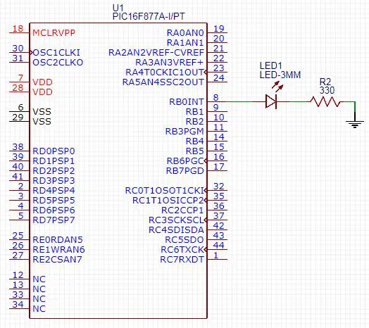
Our first task is to configure the RB0 to be an output pin (for LED) and set it to be OFF (initially)
|
1 2 |
TRISB0 = 0; RB0 = 0; |
The second task is to configure the Timer1 Module in order to operate in timer mode. We’ll use the T1CON register as well as the block diagram for the Timer1 module. Have a look yourself and determine where the clock signal should go and how to set everything up. The c-code for the Timer1 configuration part is shown below
|
1 2 3 4 5 6 7 8 9 10 11 12 13 |
// -- [[ Configure Timer1 To Operate In Timer Mode ]] -- // Clear The Timer1 Register. To start counting from 0 TMR1 = 0; // Choose the local clock source (timer mode) TMR1CS = 0; // Choose the desired prescaler ratio (1:1) T1CKPS0 = 0; T1CKPS1 = 0; // Event1 = LED ON RB0 = 1; // Switch ON Timer1 Module! TMR1ON = 1; |
Let’s substitute with the parameters of our timer module in the general equation in order to determine the number of overflows required to reach 1-second time interval. We’re using 4MHz crystal osc, 1:1 PS, initially TMR1 is 0, and the desired Tout is 1 sec. Solving for X, this will result in 15.26 overflows!
Obviously, the number of overflows should be an integer, so we’ll neglect that fraction part. Therefore, the X in our case is = 15, yet it’s an approximated estimation. This is going to be the upper limit of our global counter (C). Let’s define it globally at first
|
1 |
uint8_t C = 0; |
| Note | |||
|
Note that you should include the stdint.h header file in order to use the uint8_t variable type. As the counter C won’t reach the 255 limit, we should reserve a byte-wide variable for it. I’ve done this before using the unsigned char, and now I’m showing you the other option uint8_t which is an equivalent way of declaring single byte 8-bit variables. |
|||
Now, it’s the time to configure (enable) the Timer1 overflow interrupt. As stated earlier in Interrupts tutorial, you should look up the datasheet specifically the interrupt logic diagram in order to get this step right. The Number1 priority should be understanding the mechanics of the diagrams included in the datasheet and the code will follow don’t worry!
|
1 2 3 4 |
TMR1IE = 1; // Timer1 Interrupt Enable Bit TMR1IF = 0; // Clear The Interrupt Flag Bit PEIE = 1; // Peripherals Interrupts Enable Bit GIE = 1; // Global Interrupts Enable Bit |
Then, we’ll handle the Timer1 overflow interrupt by writing the ISR (interrupt service routine)
|
1 2 3 4 5 6 7 8 9 10 11 12 13 14 15 16 |
void interrupt ISR () { // Check The Flag Bit if (TMR1IF) { C++; if(C==15) { // Event2 = Toggle LED RB0 = ~RB0; // Clear The Global Counter C = 0; } TMR1IF = 0; // Clear The Flag Bit } } |
The full code listing for this LAB is as follows
|
1 2 3 4 5 6 7 8 9 10 11 12 13 14 15 16 17 18 19 20 21 22 23 24 25 26 27 28 29 30 31 32 33 34 35 36 37 38 39 40 41 42 43 44 45 46 47 48 49 50 51 52 53 |
#include "config.h" #include <stdint.h> uint8_t C = 0; // Global Counter Variable void main() { // -- [[ IO Configurations ]] -- TRISB0 = 0; RB0 = 0; // -- [[ Configure Timer1 To Operate In Timer Mode ]] -- // Clear The Timer1 Register. To start counting from 0 TMR1 = 0; // Choose the local clock source (timer mode) TMR1CS = 0; // Choose the desired prescaler ratio (1:1) T1CKPS0 = 0; T1CKPS1 = 0; // Event1 = LED ON RB0 = 1; // Switch ON Timer1 Module! TMR1ON = 1; // -- [[ Interrupts Configurations ]] -- TMR1IE = 1; // Timer1 Interrupt Enable Bit TMR1IF = 0; // Clear The Interrupt Flag Bit PEIE = 1; // Peripherals Interrupts Enable Bit GIE = 1; // Global Interrupts Enable Bit while(1) { // Stay IDLE ,, Timer Interrupt Will Handle Everything For Us ! } } // Interrupt Service Routine - ISR void interrupt ISR () { // Check The Flag Bit if (TMR1IF) { C++; if(C==15) { // Event2 = Toggle LED RB0 = ~RB0; // Clear The Global Counter C = 0; } TMR1IF = 0; // Clear The Flag Bit } } |
Well, it’s almost done! Cross your fingers. Hit the compile button! And we’re done with the firmware
2. Simulation
The schematic for this LAB is shown below. Just create a similar one in your simulator.
After connecting everything up in your simulator, you’ll have to double-click the MCU chip and point to the firmware code .hex file, make sure to simulate your project at the same oscillator frequency used in the code. Otherwise, the timing diagram will be messed-up.
3. Prototyping
You should have created the basic prototyping setup which we’ve demonstrated previously. If you’ve any troubles doing so, you can refer to that previous tutorial.
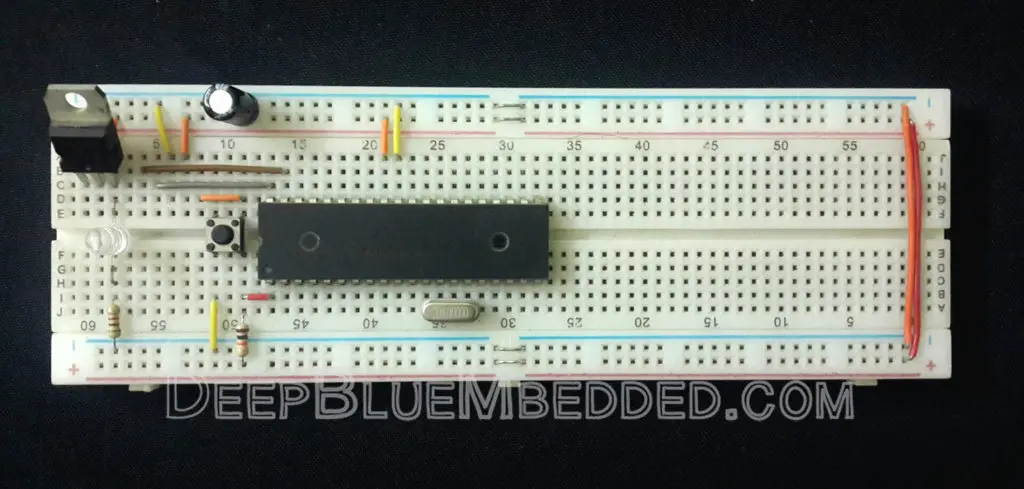
Well, hooking an LED to RB0 pin should not be that kind of a big deal. We’ve already done the tough part.
Connect your programmer’s ICSP port, Flash the Code, Plug the power supply and test this out!
The final running project in case you’re curious.
 |
Concluding Remarks
1.
Now you should have already gained a better understanding of what are timer modules technically? And how they work? What are their modes of operation? And what are the differences and applications for each mode? We’ve also developed a simple driver for the Timer1 module in order to generate fixed time intervals and use it to blink an LED.
Timer modules are actually identical in operation. They do have differences in resolution and some specifications and may be custom logic circuitry for additional features (e.g. postscalers). For now, it’s not worth the time and effort to perform those little tweaks to produce a rework for our projects built with Timer1.
As mentioned before, the main intent for this series of tutorials is to explore the embedded systems world and get more familiar with the fundamental modules within a microcontroller chip as soon as possible. That’s why we won’t be discussing any of the Timer0, Timer2, and WDT till the end of the core content of this course. However, we’ll investigate in these areas as extra (additional) materials right after completing the core tutorials.
2.
Timing VS Time Delays
After completing LAB7, one of the most common questions that I’ve used to receive is “Why to use the Timer module to blink an LED instead of generic Delays?”
Why should I perform these calculations and write 50 lines of c-code just only to blink a small LED? Won’t those 4 lines of code do the hack instead?
|
1 2 3 4 |
RB0 = 1; // LED ON __delay_ms(1000); RB0 = 0; // LED OFF __delay_ms(1000); |
Well, the answer is they won’t!
Time delays can never replace time intervals generated by timer modules. This attitude stems from a fundamental misunderstanding of how timer modules are functioning. And that’s going to be our next tutorial’s subject. (Tutorial 10)
3.
Generating 100% accurate time intervals
The second thing to note in this tutorial is the step of calculating the number of timer overflows required in order to get a 1-second time interval. Solving the general equation for X has resulted in 15.26, which we’ve arbitrarily chopped! To get the integer part 15. Won’t this generate any error? even a tiny small glitch?
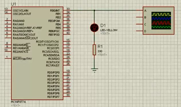
Well, the answer is absolutely YES! This act will always generate an error. Even the smallest of errors can cause substantial damage as long as it’s an accumulating error. Let’s hook the output pin (LED) to an oscilloscope (CRO) and have a closer look at the output waveform to measure the period of the output time interval.
 |
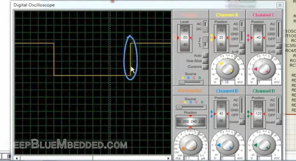 |
As you can see, there is a tiny error in the output period. It’s just less than 1-second by a tiny portion. Mathematically, this error can be easily calculated by performing the following multiplication
Output Time = Number of Overflows * Time of single overflow
Output Time = X * Toverflow
Output Time = 15 * 0.06553 = 0.9829
The Error = 1 sec – 0.98 sec = ~ 0.02 sec
The Error Percentage = ~ 2%
Despite the fact that this error is seemingly small, but it’s an accumulating error that propagates from the 1st sec. to the 2nd, 3rd, and so on. If you’ve used the timer1 module in the exact same configurations in order to fire an alarm after 12hours. The alarm will get fired after 11.75h. The small 0.02 sec error has grown to 15min over time.
What if my application is critically time-dependent? What if we need to generate a pure 100% accurate time interval? Well, we’ll do what I call Timer Pre-Loading!
And this is going to be the subject of (Tutorial 11) after the next one. So stay tuned!
| PIC Microcontrollers Course Home Page ???? | |||||||
| Previous Tutorial | Tutorial 9 | Next Tutorial | |||||
Hi.Great tutorial and I have learned so much.But you haven’t used #define _XTAL_FREQ 4000000 at the beginning of the program.Would it make difference if you used?
No, it has no effect here. We’re not using the __delay_ms() macro, so it’s OK to not define the _XTAL_FREQ identifier
Hello Khaled,
I can see a resistor and NOT gate in the T1OSC block.
If you don’t mind, could you explain how NOT gate is able to control the clock?
Thanks
Greetings JIHOON,
Well, a NOT gate with a Schmitt-Trigger output is a very simple type of TTL oscillators. Connecting a capacitor externally will generate a clock at the output of the block that you can use to clock your timer module!
check out the following link for more info about TTL schmitt-trigger oscillator.
https://en.wikipedia.org/wiki/Schmitt_trigger#Applications
I’ve done a YT video a few weeks ago about this oscillator (unfortunately for a lot of people, it’s in Arabic)
https://www.youtube.com/watch?v=7sfBA0uLtLU
I appreciate your kind reply ????
Hello
Why the Q2 bit does not toggle when Q1 *The clock input* =1 and It waits until Q0 . Q1 = 1 ?
The toggling occurs on one edge of the clock input. It will not toggle again until the same edge arrives in the next cycle. So it toggles once every input clock cycle
Thanks , I’m sorry I just forgot that.
I have just looked at the timing diagram and realized :”DD
Thanks again for your effort ❤
NP Dude! I’ll be always here for help if you need to ^^
Regards,
Hello Khaled,
Thank you for your Tutorial, it’s very helpfull,.
I want to use the timer module to cadence the frequency of my while loop, I want my while loop to turn at 10KHz(100us),
do you have any idea how can I do it
thank you
BUILD FAILED (exit value 2, total time: 3s)
main.c:40:6: error: variable has incomplete type ‘void’
void interrupt ISR()
^
main.c:40:15: error: expected ‘;’ after top level declarator
void interrupt ISR()
^
;
2 errors generated.
(908) exit status = 1
please help me what is the problem
I have the same problem , did u solve it ???
did u solve it !!
the syntax of it has been changed in the new version of the compiler to this :
void __interrupt() ISR()
change c stander to c90 from file project properties xc8 global options