| Previous Tutorial | Tutorial 31 | Next Tutorial | |||||
| STM32 Servo Motor Control With PWM Tutorial – ECUAL Servo Driver | |||||||
| STM32 Course Home Page ???? | |||||||
In this tutorial, we’ll discuss how to control servo motors using STM32 PWM to generate the control signal for servo motors. We’ll also develop all the necessary equations and code that is required to build the ECUAL servo motor driver library. I’ll show you how I built it, the available APIs, and how to use it. And finally, we’ll do a couple of LABs or examples using the ECUAL STM32 servo motor driver. While highlighting all the possible options and configurations in the driver’s config files. Without further ado, let’s get started!
[toc]
Required Components For LABs
All the example code/LABs/projects in the course are going to be done using those boards below.
- Nucleo32-L432KC (ARM Cortex-M4 @ 80MHz) or (eBay)
- Blue Pill STM32-F103 (ARM Cortex-M3 @ 72MHz) or (eBay)
- ST-Link v2 Debugger or (eBay)
| QTY | Component Name | ???? Amazon.com | ???? eBay.com |
| 2 | BreadBoard | Amazon | eBay |
| 1 | LEDs Kit | Amazon Amazon | eBay |
| 1 | Resistors Kit | Amazon Amazon | eBay |
| 1 | Capacitors Kit | Amazon Amazon | eBay & eBay |
| 2 | Jumper Wires Pack | Amazon Amazon | eBay & eBay |
| 1 | 9v Battery or DC Power Supply | Amazon Amazon Amazon | eBay |
| 1 | Micro USB Cable | Amazon | eBay |
| 1 | Push Buttons | Amazon Amazon | eBay |
| 1 | Potentiometers | Amazon Amazon | eBay |
| 4 | Micro Servo Motor (Metal Gear) | Amazon | eBay |
★ Check The Full Course Complete Kit List
Some Extremely Useful Test Equipment For Troubleshooting:
- My Digital Storage Oscilloscope (DSO): Siglent SDS1104 (on Amazon.com) (on eBay)
- FeelTech DDS Function Generator: KKMoon FY6900 (on Amazon.com) (on eBay)
- Logic Analyzer (on Amazon.com) (on eBay)
Affiliate Disclosure: When you click on links in this section and make a purchase, this can result in this site earning a commission. Affiliate programs and affiliations include, but are not limited to, the eBay Partner Network (EPN) and Amazon.com.
Introduction To Servo Motor Control
Servo Motor Control Signal
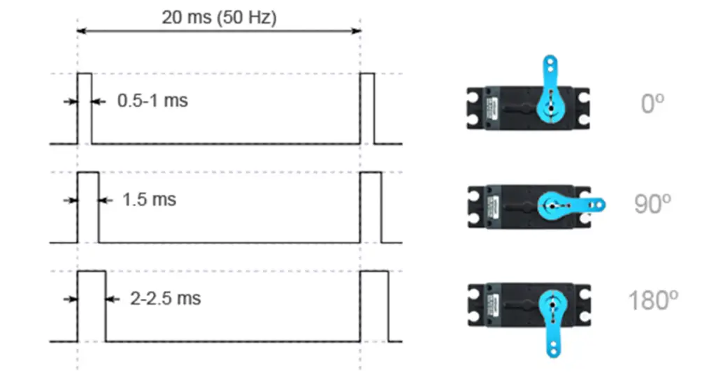
To control the position (angle) of the servo motor’s shaft, you’ll have to generate a PWM signal that has a frequency of 50Hz and a variable duty cycle. The datasheet for each stepper motor has to have the exact specifications for the pulse width that corresponds to the minimum angular position (0°) it’s called Minimum_Pulse and the pulse width that corresponds to the maximum angular position (180°) and we’ll call this the Maximum_Pulse.
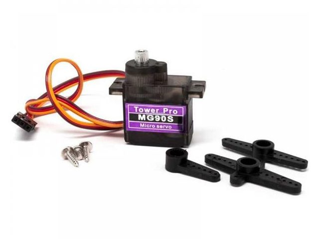
The servo motor that I’ve in my LAB and will be using today is the micro servo with metal gear MG90s. Unfortunately, “The datasheet” found on the internet seems to be a poorly translated Chinese paper with a little bit of information about the control signal specs and it turned out to be false. Other than that, the practical experimentation didn’t only give me the exact pulse widths that correspond to (0° & 180°) but it also proved that those little motors are not the same. A quick characterization with a DDS function generator and a DSO has given me the exact figures for the min & max pulse widths (in ms).
This picture shows what are the values I’ve got for a different 4 servo motors, and I preferred to label them. In a previous tutorial, I’ve assumed that the minimum pulse is 0.6ms and the maximum pulse is 2.4ms in order to make everything as simple as possible and not trying to be a perfectionist about it. But in today’s tutorial, I’ll make a room for these values to be in our code configurations and to take effect. All in all, it’s not a much of a big deal anyway!

Servo Motor Resolution
The angular position of the servo motor is determined by the pulse width of the PWM signal. Therefore, the PWM signal’s resolution dictates how fine can we adjust the servo motor’s angle. The range of the angle in degrees is from 0 up to 180 will get mapped to whatever values that produces a pulse width between Minimum_pulse and Maximum_Pulse and all depends on the PWM resolution itself.
Maximizing the resolution will be one of our targets while deriving the equations to be used in code later on. The STM32 PWM hardware can go up to 16-Bit @ 50Hz and we shall seek to get as close as possible to that limit.
And here is an example for clarification of the concept of resolution.
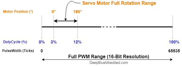
Just imagine that we’ve set up the PWM hardware to generate a PWM signal with a frequency of 50Hz and the duty cycle has a 16-Bit of resolution. This means that the duty cycle has 65536 discrete levels between (0% to 100%). That’s a too accurate control signal for such an application and seems more like overkill but let’s continue.
Suppose that our servo motor has a minimum pulse width of 0.6ms (for the 0° position) and a maximum pulse of 2.4ms (for the 180° position). This means that the entire range of PWM signal that covers the full motor rotation is from 3% up to 12%. Why these numbers? well, the minimum pulse is 0.6ms in width as time, in order to get the duty cycle percentage that represents this pulse width time, we’ll divide 0.6 by 20ms which is the period of the PWM signal (which has a frequency of 50Hz, so it’s period is 20ms). This division will give you that the minimum pulse 0.6/20 is a 3% duty cycle. And the maximum pulse is 12% duty cycle be the same procedure.
Now, given that the entire PWM range (0% up to 100%) has a 16-Bit of resolution or 65536 discrete levels. The motor rotation range is (12% – 3% = 9%) and this 9% has (9/100)*65536 discrete levels of control. This means that the servo motor’s angular range (0° up to 180°) is mapped to nearly 5900 discrete levels. This means we can control the servo motor’s angle with a precision of 0.03°. Which is not true! This is obviously ridiculous due to mechanical limitations and the way this motor is built. However, math is always true but this can’t be practically achieved at least with those cheap little motors.
Power Requirements & Precautions
First of all, if you’re using a decent servo motor that has well-documented specs, do check them out and see the current draw and its power consumption. Mostly no servo motor can work directly from the USB programmer circuit as it is. Except for a few tiny servo motors that may be an exception but in most cases, you’ll be in need to connect your servo motors to an external power source.
The same power source used by the microcontroller can be used of course but please make sure you’re decoupling the power supply correctly and bulk bypass capacitors are placed near the power supply and small caps near the MCU power input pins.
There are servo motors that can rotate 360 degrees freely and there are other types like mine that are limited to 180 degrees. There is a mechanical buffer that blocks motion at this angle. Reaching this angle can cause the servo motor to release some wining sound and draw a significant amount of current compared to its normal conditions. This situation needs to be considered as well and if it can’t be well-handled, then it should be avoided in the first place. Maybe by capping the maximum pulse width (if it’s 2.4ms, just use 2.3 or something like that).
| That was a quick introduction for servo motors and control signals. For more info, I’d highly recommend those three articles that were published in the past year. The examples are built around 8-Bit MCUs but the information is still relevant and helpful if you’re dealing with servo motors for the first time. This should be a good starting point. | ||
 |
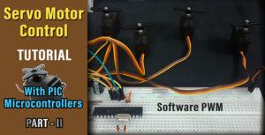 |
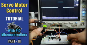 |
STM32 ECUAL / Servo Motor Driver
The ECUAL Servo motor driver is built for STM32 microcontrollers using the hardware PWM channels in various timers. You’ll have to configure an instance of it and used the APIs to control your motor and that’s all. The code should be easily ported to any other STM32 microcontroller or reconfigured to use any timer or channel you want just as we’ll see in this section. And here is a link for the course’s repo, and you’ll find the Servo driver in the ECUAL directory as usual.
Servo Motor Driver Code Files
The servo motor driver consists of the following files:
|
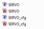 |
You’ll need only to modify the configuration files. The source code for this driver is found in (SERVO.c) and to use it you’ll include the header (SERVO.h). Nothing in the source code needs to be changed at all unless you need to add any extra features or customize the driver for your application’s needs. For today’s labs, we’ll only be changing the configuration files to build some test applications.
Therefore, I’ll write here the code listing for the SERVO.h & SERVO_cfg.c files.
SERVO.h File
|
1 2 3 4 5 6 7 8 9 10 11 12 13 14 15 16 17 18 19 20 21 22 23 24 25 26 27 28 |
// The Number OF Servo Motors To Be Used In The Project #define SERVO_NUM 1 typedef struct { GPIO_TypeDef * SERVO_GPIO; uint16_t SERVO_PIN; TIM_TypeDef* TIM_Instance; uint32_t* TIM_CCRx; uint32_t PWM_TIM_CH; uint32_t TIM_CLK; float MinPulse; float MaxPulse; }SERVO_CfgType; /*-----[ Prototypes For All Functions ]-----*/ void SERVO_Init(uint16_t au16_SERVO_Instance); void SERVO_MoveTo(uint16_t au16_SERVO_Instance, float af_Angle); void SERVO_RawMove(uint16_t au16_SERVO_Instance, uint16_t au16_Pulse); uint16_t SERVO_Get_MaxPulse(uint16_t au16_SERVO_Instance); uint16_t SERVO_Get_MinPulse(uint16_t au16_SERVO_Instance); void SERVO_Sweep(uint16_t au16_SERVO_Instance); |
If you’re willing to use many servo motors, just adjust that number definition (SERVO_NUM). And we’ll do this in the LABs of today’s tutorial.
SERVO_cfg.c File
|
1 2 3 4 5 6 7 8 9 10 11 12 13 14 15 16 |
#include "SERVO.h" const SERVO_CfgType SERVO_CfgParam[SERVO_NUM] = { // Servo Motor 1 Configurations { GPIOA, GPIO_PIN_0, TIM2, &TIM2->CCR1, TIM_CHANNEL_1, 72000000, 0.65, 2.3 } } |
I’ll discuss those configuration parameters in the next section down below.
Servo Motor Driver APIs
As you’ve seen in the SERVO.h file, the provided APIs does all the basic functionalities that you may need from a servo driver library. It initialized the PWM hardware & GPIO pin required to generate the 50Hz control signal.
The servo_moveto function takes the number of the servo motor you wanna command and an angle to move its shaft to that angle (from 0 up to 180).
The structure of the files and the provided APIs look very intuitive and self-explanatory to me. And the example LABs will put everything under test and you’ll see how and when to use each of these functions.
Available Configurations For ECUAL Servo Driver
From the code above in SERVO.h & SERVO_cfg.c you can see that there are a handful of parameters that you (the application programmer) can actually configure for each servo motor individually. They are as follows:
- The timer module you wanna use for this servo motor PWM generation (TIM1, 2, or whatever)
- The timer PWM Channel number that you wanna use for this servo motor (CH1, 2, 3, ..)
- The GPIO port for the PWM CHx pin
- The PIN number for the PWM CHx pin
- The clock frequency (in Hz) for the timer you’re going to use
- A pointer to the Timer CCRx register for the chosen PWM Channel
- The minimum pulse width for the servo motor as in its datasheet (0.6ms, 0.5ms, or whatever)
- The maximum pulse width for the servo motor (2.4ms, 2.5ms, or whatever value)
Typical Usage Application Example
Here is a typical usage application for this driver in order to initialize a servo motor and move it from 0 to 180 back and forth. It’ll be something like this shown below.
|
1 2 3 4 5 6 7 8 9 10 11 12 13 14 15 16 |
#include "ECUAL/SERVO/SERVO.h" #define SERVO_Motor1 0 void main() { SERVO_Init(SERVO_Motor1); while(1) { SERVO_MoveTo(SERVO_Motor1, 0); Delay_ms(2000); SERVO_MoveTo(SERVO_Motor1, 180); Delay_ms(2000); } } |
STM32 PWM For Servo Motor Control
In this section, I’ll show you the derivation for most of the equations used in the driver’s code that may seem ambiguous and highlight the goals and intentions I had while writing it in this way.
Prescaler Value
And let’s start with the timer Prescaler (PSC) and Auto-Reload Register (ARR). We need to calculate those parameters and write the number in the respective register. In order to control the PWM’s frequency and make it equal to 50Hz which is required by the servo motor, we’ll use the following equation.
![]()
Recall the discussion of the PWM resolution at the beginning of this tutorial. I said that it’s one of my goals to maximize the PWM resolution, hence in this equation, I’ve assumed the ARR value to be 65535 which is the maximum possible value that achieves the maximum possible resolution. Then plug in the timer clock frequency FCLK, the 50Hz for FPWM and solve for PSC. This calculation is done in code in the initialization function.
PSC = FCLK / 3276800
|
1 |
PSC_Value = (uint32_t)(SERVO_CfgParam[au16_SERVO_Instance].TIM_CLK/3276800.0); |
And pay attention to the fact that it’ll maximize the ARR but won’t make it 65535 exactly! it’ll just pick for us the best Prescaler value that maximizes the PWM range (resolution). Therefore, we still need to find out the value of ARR that should be written in its respective register.
ARR Register Value
To find out the value of ARR you’ll use also the first equation
![]()
Given that FCLK is known as well as FPWM, even PSC is now known. After we’ve found the PSC that maximizes PWM resolution, now plug all variables in the equation and solve for ARR.
|
1 |
ARR_Value = (uint32_t) ((SERVO_CfgParam[au16_SERVO_Instance].TIM_CLK / (50.0*(PSC_Value+1.0)))-1.0); |
Pulse Width Min & Max Period
Last but not least, the servo motor’s minimum & maximum pulse width specs given in the datasheet. Should also be converted into digital values that represent the number of ticks in the CCRx register of the respective PWM channel to achieve those pulse widths and hence control the servo motor’s angle.
Calculating both numbers is also critical for determining the full range to which we’ll be mapping the angle given by the user. When a user call the moveTo function and gives me 90 degrees. What should be the value of the CCRx register to achieve this?
Well, it should be in the middle of the range, as 90degree is in middle between (0 and 180). But we still don’t know the number of ticks that represent it. Hence, it’s so important now to find those values.
Depending on the fact that the PWM signal’s frequency is 50Hz, so it’s period is 20ms. And the min_pulse is given to us in ms as well by the user. Let’s say it’s 0.6ms, so the PWM duty cycle is 0.6/20 = 3%. To achieve 3% duty cycle, the value of the CCRx register will be calculated from this equation.
![]()
Period_Min = ARR x (min_pulse_width / 20ms)
Period_Max = ARR x (max_pulse_width / 20ms)
|
1 2 |
gs_SERVO_info[au16_SERVO_Instance].Period_Min = (uint16_t) (ARR_Value * (SERVO_CfgParam[au16_SERVO_Instance].MinPulse/20.0)); gs_SERVO_info[au16_SERVO_Instance].Period_Max = (uint16_t) (ARR_Value * (SERVO_CfgParam[au16_SERVO_Instance].MaxPulse/20.0)); |
And that’s it for most of the parts that I think would be problematic and ambiguous for the readers. If there still something not clear enough, drop me a comment I’ll be here for help as usual.
STM32 PWM Servo Motor Control – Basic LAB
| LAB Number | 26 |
| LAB Title | STM32 Servo Motor Control – Basic LAB |
- Set up a new project as usual with system clock @ 72MHz
- Add the ECUAL / SERVO driver files to our project
- configure a servo motor instance in SERVO_cfg.c file
- Initialize the servo motor and command it to move to the following angle positions in the same pattern (0, 45, 90, 135, 180, 90, 0)
And now, let’s build this system step-by-step
Step1: Open CubeMX & Create New Project
Step2: Choose The Target MCU & Double-Click Its Name
STM32F103C8
Step3: Go To The Clock Configuration
Step4: Set The System Clock To Be 72MHz
Step5: Generate The Initialization Code & Open The Project In Your IDE
Step6: Add the ECUAL SERVO driver files to your project
Follow This Tutorial which shows you How To Add Any ECUAL Driver To An STM32 Project step-by-step.

Step7: One Last step is to open stm32f1xx_hal_conf.h file in the include directory and uncomment the following line of code
|
1 |
#define HAL_TIM_MODULE_ENABLED |
To allow the HAL timer drivers to be included and compiled as our servo driver is built on top of the HAL driver from STMicroelectronics. Now, we’re ready to write a test application code and compile it.
Here is The Application Code For This LAB (main.c)
|
1 2 3 4 5 6 7 8 9 10 11 12 13 14 15 16 17 18 19 20 21 22 23 24 25 26 27 28 29 30 31 |
#include "main.h" #include "../ECUAL/SERVO/SERVO.h" // The Servo Instance Index Must Start From 0 #define SERVO_Motor1 0 void SystemClock_Config(void); static void MX_GPIO_Init(void); int main(void) { HAL_Init(); SystemClock_Config(); MX_GPIO_Init(); SERVO_Init(SERVO_Motor1); while (1) { SERVO_MoveTo(SERVO_Motor1, 0); HAL_Delay(1000); SERVO_MoveTo(SERVO_Motor1, 45); HAL_Delay(500); SERVO_MoveTo(SERVO_Motor1, 90); HAL_Delay(500); SERVO_MoveTo(SERVO_Motor1, 135); HAL_Delay(500); SERVO_MoveTo(SERVO_Motor1, 180); HAL_Delay(500); SERVO_MoveTo(SERVO_Motor1, 90); HAL_Delay(1000); } } |
And here is the SERVO_cfg.c configuration file. As you can see here, I’m using Timer2 channel1 with a frequency of 72Mz, the servo’s min pulse is 0.65ms, the max is 2.3ms, the GPIO port is A, the pin is A0.
|
1 2 3 4 5 6 7 8 9 10 11 12 13 14 15 16 |
#include "SERVO.h" const SERVO_CfgType SERVO_CfgParam[SERVO_NUM] = { // Servo Motor 1 Configurations { GPIOA, GPIO_PIN_0, TIM2, &TIM2->CCR1, TIM_CHANNEL_1, 72000000, 0.65, 2.3 } }; |
Download The STM32 Servo Motor Control Basic LAB26
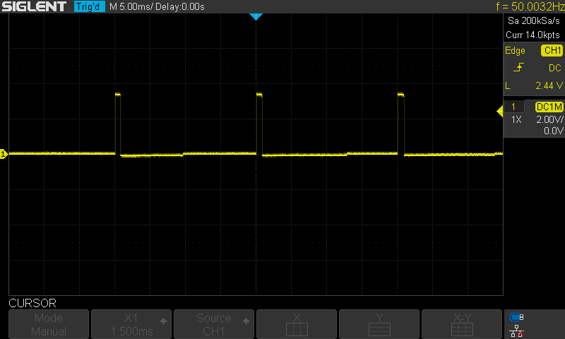
The Result For This LAB Testing (Video)
Here is a snapshot for the Servo PWM Signal (a clean 50Hz)
Extremely Important Notes From This LAB
First of all, the GPIO pin selection is not an arbitrary process. You just can’t configure the driver to use Timer2 channel 1 and configure the pin to whatever you want. Once you’ve made your decision on which timer and which channel you want to assign to your servo motor, you’ll have to check its pin GPIO port and number and use that in your configuration.
Another note is the servo motor index (instance number) you’re using while calling the APIs. For an application where is only 1 servo motor the SERVO_NUM define is 1 and the index you shall be using is 0. Therefore, you’ll init this servo like this
SERVO_Init(0);
However, if more than a servo motor is being used, the indexing will start also from 0 and counts up. Therefore, in order to initialize multiple motors, you’ll do this.
SERVO_Init(0);
SERVO_Init(1);
And so on.
Another note is the power source. As you’ve seen in the video I’m using a power bank and the Servo motor is connected to the +5v power pin on the Blue Pill board.
STM32 Analog Servo Motor Control + Knob LAB
| LAB Number | 27 |
| LAB Title | STM32 Servo Motor Control With Knob (ADC Input) LAB |
- Set up a new project as usual with system clock @ 72MHz
- Set up an ADC analog input channel (CH7 on A7 pin)
- Add the ECUAL / SERVO driver files to our project
- configure a servo motor instance in SERVO_cfg.c file
- Initialize the servo motor and read the ADC 12-Bit result and map it between the maximum & minimum pulse widths for the servo motor to control its angular position
And now, let’s build this system step-by-step
Step1: Open CubeMX & Create New Project
Step2: Choose The Target MCU & Double-Click Its Name
STM32F103C8
Step3: Go To The Clock Configuration
Step4: Set The System Clock To Be 72MHz
Step5: In ADC1 Tab Enable CH7 Analog Input
Step6: Generate The Initialization Code & Open The Project In Your IDE
Step7: Add the ECUAL SERVO driver files to your project
Follow This Tutorial which shows you How To Add Any ECUAL Driver To An STM32 Project step-by-step.
Step8: One Last step is to open stm32f1xx_hal_conf.h file in the include directory and uncomment the following line of code
|
1 |
#define HAL_TIM_MODULE_ENABLED |
To allow the HAL timer drivers to be included and compiled as our servo driver is built on top of the HAL driver from STMicroelectronics. Now, we’re ready to write a test application code and compile it.
Here is The Application Code For This LAB (main.c)
|
1 2 3 4 5 6 7 8 9 10 11 12 13 14 15 16 17 18 19 20 21 22 23 24 25 26 27 28 29 30 31 32 33 34 35 36 37 38 39 40 41 42 43 |
#include "main.h" #include "../ECUAL/SERVO/SERVO.h" #define SERVO_Motor1 0 ADC_HandleTypeDef hadc1; void SystemClock_Config(void); static void MX_GPIO_Init(void); static void MX_ADC1_Init(void); int main(void) { uint16_t AD_RES = 0; uint16_t Min_Pulse = 0, Max_Pulse = 0; float temp = 0.0; uint16_t Servo_Pulse = 0; HAL_Init(); SystemClock_Config(); MX_GPIO_Init(); MX_ADC1_Init(); SERVO_Init(SERVO_Motor1); Min_Pulse = SERVO_Get_MinPulse(SERVO_Motor1); Max_Pulse = SERVO_Get_MaxPulse(SERVO_Motor1); while (1) { // Start ADC Conversion HAL_ADC_Start(&hadc1); // Poll ADC1 Perihperal & TimeOut = 1mSec HAL_ADC_PollForConversion(&hadc1, 1); // Read The ADC Conversion Result & Map It To PWM DutyCycle AD_RES = HAL_ADC_GetValue(&hadc1); // Map The ADC Result To Servo Pulse Width temp = ((Max_Pulse-Min_Pulse)/4096.0); Servo_Pulse = (uint16_t)(AD_RES*temp) + Min_Pulse; // Send The Raw Servo Pulse Width To The PWM Hardware SERVO_RawMove(SERVO_Motor1, Servo_Pulse); HAL_Delay(10); } } |
And here is the SERVO_cfg.c configuration file. As you can see here, I’m using Timer2 channel1 with a frequency of 72Mz, the servo’s min pulse is 0.65ms, the max is 2.3ms, the GPIO port is A, the pin is A0.
|
1 2 3 4 5 6 7 8 9 10 11 12 13 14 15 16 |
#include "SERVO.h" const SERVO_CfgType SERVO_CfgParam[SERVO_NUM] = { // Servo Motor 1 Configurations { GPIOA, GPIO_PIN_0, TIM2, &TIM2->CCR1, TIM_CHANNEL_1, 72000000, 0.65, 2.3 } }; |
Download The STM32 Servo Motor Control With Knob LAB27
The Result For This LAB Testing (Video)
STM32 Multi Servo Motors Control – LAB
| LAB Number | 28 |
| LAB Title | STM32 Multi Servo Motors Control LAB |
- Set up a new project as usual with system clock @ 72MHz
- Add the ECUAL / SERVO driver files to our project
- configure 4 servo motor instances in SERVO_cfg.c file
- Initialize the servo motors and command them individually to make whatever pattern you want
And now, let’s build this system step-by-step
Step1: Open CubeMX & Create New Project
Step2: Choose The Target MCU & Double-Click Its Name
STM32F103C8
Step3: Go To The Clock Configuration
Step4: Set The System Clock To Be 72MHz
Step5: Generate The Initialization Code & Open The Project In Your IDE
Step6: Add the ECUAL SERVO driver files to your project
Follow This Tutorial which shows you How To Add Any ECUAL Driver To An STM32 Project step-by-step.
Step7: One Last step is to open stm32f1xx_hal_conf.h file in the include directory and uncomment the following line of code
|
1 |
#define HAL_TIM_MODULE_ENABLED |
To allow the HAL timer drivers to be included and compiled as our servo driver is built on top of the HAL driver from STMicroelectronics. Now, we’re ready to write a test application code and compile it.
Here is The Application Code For This LAB (main.c)
|
1 2 3 4 5 6 7 8 9 10 11 12 13 14 15 16 17 18 19 20 21 22 23 24 25 26 27 28 29 30 31 32 33 34 35 36 37 38 39 40 41 42 43 44 45 46 47 48 49 50 51 52 |
#include "main.h" #include "../ECUAL/SERVO/SERVO.h" #define SERVO_Motor1 0 #define SERVO_Motor2 1 #define SERVO_Motor3 2 #define SERVO_Motor4 3 void SystemClock_Config(void); static void MX_GPIO_Init(void); int main(void) { HAL_Init(); SystemClock_Config(); MX_GPIO_Init(); SERVO_Init(SERVO_Motor1); SERVO_Init(SERVO_Motor2); SERVO_Init(SERVO_Motor3); SERVO_Init(SERVO_Motor4); while (1) { SERVO_MoveTo(SERVO_Motor1, 0); SERVO_MoveTo(SERVO_Motor2, 0); SERVO_MoveTo(SERVO_Motor3, 0); SERVO_MoveTo(SERVO_Motor4, 0); HAL_Delay(1500); SERVO_MoveTo(SERVO_Motor1, 180); HAL_Delay(500); SERVO_MoveTo(SERVO_Motor2, 180); HAL_Delay(500); SERVO_MoveTo(SERVO_Motor3, 180); HAL_Delay(500); SERVO_MoveTo(SERVO_Motor4, 180); HAL_Delay(1500); SERVO_MoveTo(SERVO_Motor1, 0); SERVO_MoveTo(SERVO_Motor2, 0); SERVO_MoveTo(SERVO_Motor3, 0); SERVO_MoveTo(SERVO_Motor4, 0); HAL_Delay(1500); SERVO_MoveTo(SERVO_Motor1, 180); SERVO_MoveTo(SERVO_Motor2, 180); SERVO_MoveTo(SERVO_Motor3, 180); SERVO_MoveTo(SERVO_Motor4, 180); HAL_Delay(1500); } } |
And here is the SERVO_cfg.c configuration file.
|
1 2 3 4 5 6 7 8 9 10 11 12 13 14 15 16 17 18 19 20 21 22 23 24 25 26 27 28 29 30 31 32 33 34 35 36 37 38 39 40 41 42 43 44 45 46 47 48 49 |
#include "SERVO.h" const SERVO_CfgType SERVO_CfgParam[SERVO_NUM] = { // Servo Motor 1 Configurations { GPIOA, GPIO_PIN_0, TIM2, &TIM2->CCR1, TIM_CHANNEL_1, 72000000, 0.65, 2.3 }, // Servo Motor 2 Configurations { GPIOA, GPIO_PIN_3, TIM2, &TIM2->CCR4, TIM_CHANNEL_4, 72000000, 0.75, 2.5 }, // Servo Motor 3 Configurations { GPIOB, GPIO_PIN_0, TIM3, &TIM3->CCR3, TIM_CHANNEL_3, 72000000, 0.62, 2.4 }, // Servo Motor 4 Configurations { GPIOB, GPIO_PIN_9, TIM4, &TIM4->CCR4, TIM_CHANNEL_4, 72000000, 0.55, 2.35 } }; |
As you can see here:
I’m mixing between different timers and PWM channels in order to give you an idea of how can you easily configure this driver code. But I’d recommend using one-timer and its 4 channels if it’s possible in your application. Using a timer for servo motor control will restrict the timing in such a way that’s convenient for the servo driver but not the other parts of the system that wanna share the same resource.
For Servo Motor1: TIM2, Ch1, pin A0
For Servo Motor2: TIM2, Ch4, pin A3
For Servo Motor3: TIM3, Ch3, pin B0
For Servo Motor4: TIM4, Ch4, pin B9
Don’t forget to change this line of code in the SERVO.h file to make the number of servo motors 4
|
1 2 |
// The Number OF Servo Motors To Be Used In The Project #define SERVO_NUM 4 |
Download The STM32 Multi Servo Motors Control LAB28
The Result For This LAB Testing (Video)
One Last Testing For STM32 Servo Driver
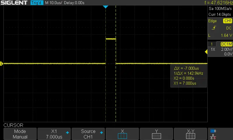
I’ve also done one last test that I’d like to share with you. It was an approximate measurement for the execution time for the function SERVO_MoveTo(). Because we’re going to build a very basic operating system in the future and also make some RTOS applications, it’s important to know the execution time of such routines like the servo motor controller.
I’ve used a GPIO pin configured in fast mode push-pull driver output for fast edges switching on the output pin and driven it high before calling the servo move function and bring it low when it returns. And it turned out to be 7μs which is amazing as a beginning and needs no more optimization in the meantime. So, that’s great! and we’ll move on to the next tutorial.
Did you find this helpful? If yes, please consider supporting this work and sharing these tutorials!
Stay tuned for the upcoming tutorials and don’t forget to SHARE these tutorials. And consider SUPPORTING this work to keep publishing free content just like this!
| Previous Tutorial | Tutorial 31 | Next Tutorial | |||||