| Previous Tutorial | Tutorial 43 | Next Tutorial | |||||
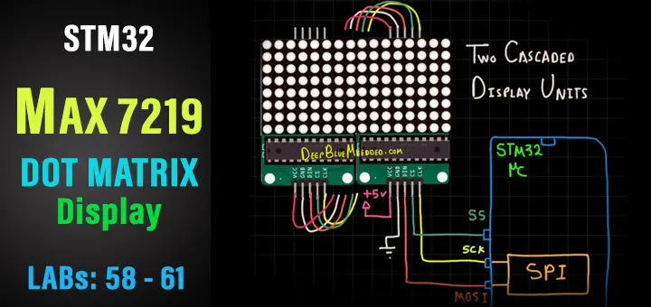
| STM32 MAX7219 Dot Matrix Display Interfacing Library | |||||||
| STM32 Course Home Page ???? | |||||||
In this tutorial, we’ll be interfacing STM32 with the MAX7219 Dot Matrix Display. Starting with how dot matrix display works and the features of the MAX7219 driver IC highlighted from the datasheet. Then, we’ll develop our own Dot Matrix Display Library (driver) based on HAL for STM32 microcontrollers as we’ve used to in this series of tutorials.
I’ll be using the STM32F103C8T6 (blue pill) board, as usual. However, you can still use any other STM32 microcontroller part instead. I’ll show you how my library works, the available APIs, and so on. For testing our library, there will be 4 LABs in this tutorial. To get you started and help you understand the operation of each part in the systems we’ll be building. Without further ado, let’s get right into it!
In this tutorial: 4 LABs
| LAB 58 | STM32 With 1 Independent Dot Matrix Display Unit (1 Module No Cascading) – Static Mode | ||||||
| LAB 59 | STM32 With 2 Independent Dot Matrix Display Units (1 Module Per Unit, No Cascading) – Static Mode | ||||||
| LAB 60 | STM32 With 1 Independent Dot Matrix Display Unit (2 Cascaded Modules) – Scrolling Mode | ||||||
| LAB 61 | STM32 With 1 Independent Dot Matrix Display Unit (2 Cascaded Modules) – Scrolling Mode + Manual Scroll Speed Control | ||||||
[toc]
Required Components For LABs
All the example code/LABs/projects in the course are going to be done using those boards below.
- Nucleo32-L432KC (ARM Cortex-M4 @ 80MHz) or (eBay)
- Blue Pill STM32-F103 (ARM Cortex-M3 @ 72MHz) or (eBay)
- ST-Link v2 Debugger or (eBay)
| QTY | Component Name | ???? Amazon.com | ???? eBay.com |
| 2 | BreadBoard | Amazon | eBay |
| 1 | LEDs Kit | Amazon Amazon | eBay |
| 1 | Resistors Kit | Amazon Amazon | eBay |
| 1 | Capacitors Kit | Amazon Amazon | eBay & eBay |
| 2 | Jumper Wires Pack | Amazon Amazon | eBay & eBay |
| 1 | 9v Battery or DC Power Supply | Amazon Amazon Amazon | eBay |
| 1 | Micro USB Cable | Amazon | eBay |
| 2 | Push Buttons | Amazon Amazon | eBay |
| 1 | Potentiometers | Amazon Amazon | eBay |
| any | Dot Matrix Display Module | Amazon | eBay |
| 1 | USB-TTL Converter or FTDI Chip | Amazon Amazon | eBay eBay |
★ Check The Full Course Complete Kit List
Some Extremely Useful Test Equipment For Troubleshooting:
- My Digital Storage Oscilloscope (DSO): Siglent SDS1104 (on Amazon.com) (on eBay)
- FeelTech DDS Function Generator: KKMoon FY6900 (on Amazon.com) (on eBay)
- Logic Analyzer (on Amazon.com) (on eBay)
Affiliate Disclosure: When you click on links in this section and make a purchase, this can result in this site earning a commission. Affiliate programs and affiliations include, but are not limited to, the eBay Partner Network (EPN) and Amazon.com.
MAX7219 Dot Matrix Module
MAX7219 Dot Matrix Module Description
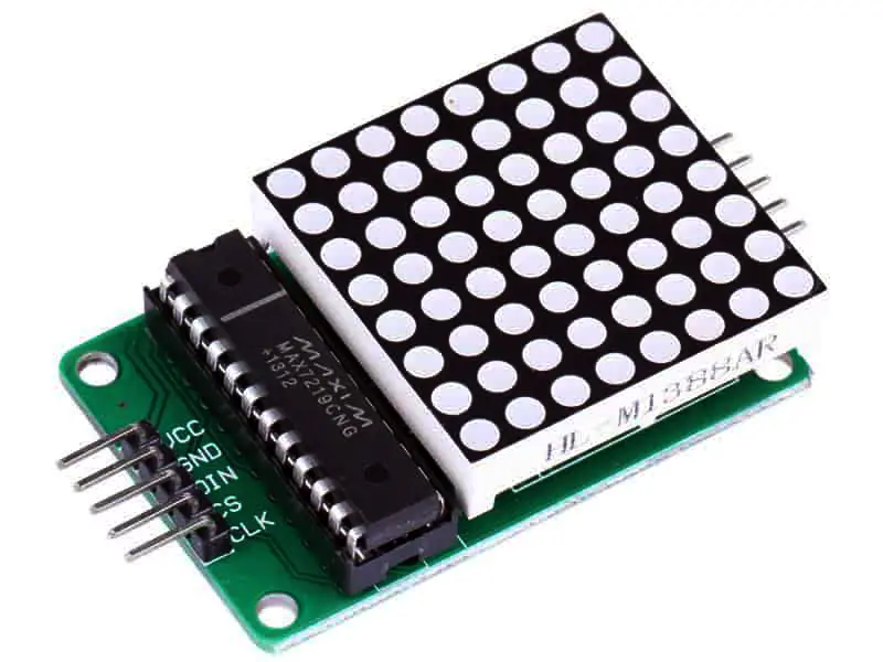
This is one of the most popular display modules that can be used in a wide range of projects. Mainly in any project where you need to have a display that could be seen from such a far distance. Unlike small LCD screens that could only be used in close-range sort of applications, the dot matrix display is more fitted to showing messages or advertisements for a long distance.
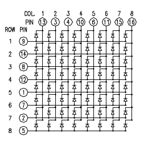
Just like the keypad matrix, the dot matrix display consists also of multiple rows and columns. One column can be controlled at a time, so we need to keep looping through all the columns quickly enough to trick the human eye to see what we want to show (which is called persistence of vision – POV).
Instead of having to do the multiplexing work by our target microcontroller, the dot matrix module has a MAX7219 driver IC that will handle these multiplexing refresh cycles for us. It does also control the brightness of the LED units and has a very easy-to-use SPI bus interface. With an SDO pin to shift data out to the adjacent unit so that we can cascade as many dot-matrix units as we want and still control everything using one SPI peripheral.
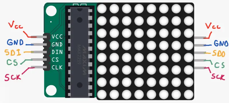
MAX7219 Dot Matrix Module Pinout
MAX7219 IC Technical Specs
Here are some of the technical features for the HC-05 Bluetooth modules:
- Operating Voltage: 4V to 5.5V ( Typically +5V )
- 10MHz Serial Interface
- Individual LED Segment Control
- Decode/No-Decode Digit Selection
- 150µA Low-Power Shutdown (Data Retained)
- Digital and Analog Brightness Control
- Display Blanked on Power-Up
- Drive Common-Cathode LED Display
- Slew-Rate Limited Segment Drivers for Lower EMI (MAX7221)
- SPI, QSPI, MICROWIRE Serial Interface (MAX7221)
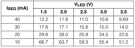
This driver IC gives you programmable control over the LED unit brightness with the maximum current being limited by the RSET resistor on the module’s board. Using this table you can change the upper limit for the drive capability if needed.
And here is the functional block diagram for the internal structure of the MAX7219 driver IC. So you can see where the SPI data we send to it goes. There are 2 main registers for each data transaction one for data and the other for the address. So that we can address the specific column to be changed or send some command operations as shown next.
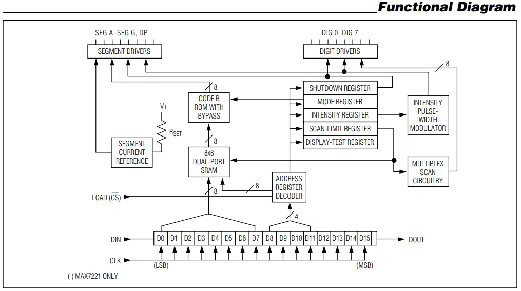
As you can see now, the driver IC does everything we need without having to handle all of that by the target microcontroller itself which is absolutely advantageous. But the thing we need to know is how to address and control this driver IC. For that, we’ll check the datasheet for the register map table to know the addresses and commands available.
There are some other important tables that you should check in the datasheet if you’d like to use this IC for 7-Segment display units not only dot matrix. But it’s out of context for this tutorial.
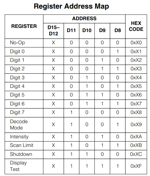
Refer To The Datasheet For More Info About MAX7219 Driver IC.
STM32 MAX7219 Dot Matrix Module Interfacing
STM32 & MAX7219 Dot Matrix Display Module Connection Diagram
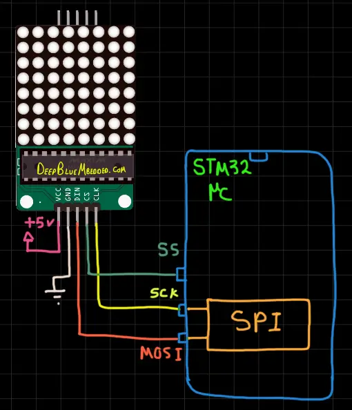
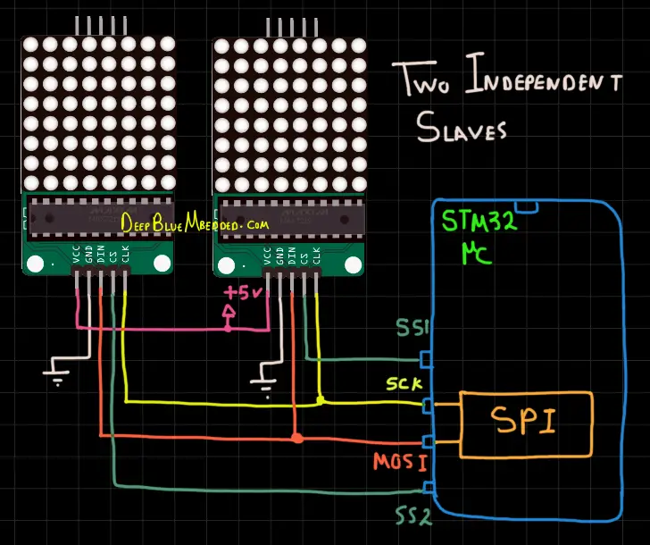
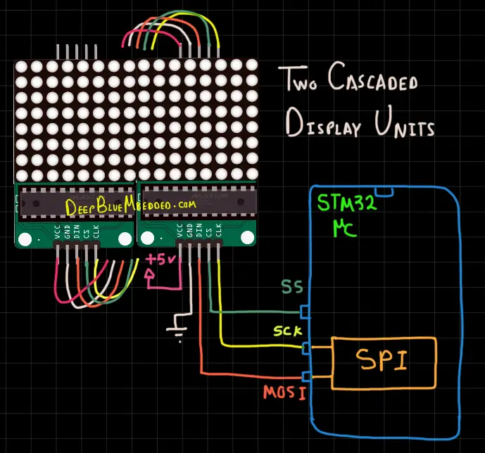
Here are the STM32 MAX7219 dot matrix connection diagrams for single unit display, two independent slave units, and finally two or more cascaded display units.
Single Unit Display
Two Independent Slave Units Display
Two Cascaded Units Display
Guidelines For Designing Our MAX7219 Dot Matrix Driver (Library)
Here are some guidelines and requirements that we need to consider before designing the Dot Matrix driver library. It can be improved in the future but for the first version, it should be in line with the following:
- Has Configurable SPIx For Communicating With The MAX7219 Driver
- Has Configurable TIMERx To Provide timing for scrolling mode (if used)
- Has Configurable Operating Mode ( Static Display or Scrolling Mode )
- Has Configurable display units count, brightness, and scrolling speed (if used)
- Has APIs to write to display units in both modes (cascaded scrolling or independent static units)
STM32 MAX7219 Dot Matrix Library (Driver)
The ECUAL DOT_MATRIX driver is built for STM32 microcontrollers using one Timer for all timing purposes and one SPI peripheral for communication with MAX7219 ICs. You’ll have to configure an instance of it and use the APIs to initialize, write, clear, or update the display with the ability to control the scrolling mode or speed, and more other features to be detailed hereafter.
The code should be easily ported to any other STM32 microcontroller or reconfigured to use any Timer and SPI peripheral that you want just as we’ll see in this section. And here is a link for the course’s repo, where you’ll find the DOT_MATRIX driver in the ECUAL directory as usual.
DOT Matrix Driver Code Files
The DOT_MATRIX driver consists of the following files:
|
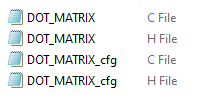 |
You’ll need only to modify the configuration files. The source code for this driver is found in (DOT_MATRIX.c) and to use it you’ll include the header (DOT_MATRIX.h). Nothing in the source code needs to be changed at all unless you need to add any extra features or customize the driver for your application’s needs. For today’s LABs, we’ll only be changing the configuration files to build some test applications.
Therefore, I’ll write here the code listing for the DOT_MATRIX.h & DOT_MATRIX_cfg.c files.
DOT_MATRIX.h File
|
1 2 3 4 5 6 7 8 9 10 11 12 13 14 15 16 17 18 19 20 21 22 23 24 25 26 27 28 29 30 31 32 33 34 35 36 37 38 39 40 41 42 43 44 45 46 47 48 49 50 51 52 53 54 55 56 57 58 59 60 61 62 63 64 |
// Replace The "#include" File Below With The CPU Relevant One For Your Board #include "stm32f1xx.h" // The Number OF Separate DOT MATRIX Units (Whether Single or Cascaded) To Be Used In The Project #define DOT_MATRIX_UNITS 1 // The Matrix Units Count Of The Longest Cascaded String In The System #define MAX_CASCADED_NUM 2 // DOT Matrix SPI Options #define DOT_MATRIX_SPI SPI1 // DOT Matrix Timer Base Options #define MATRIX_TIMER_EN 1 #define MATRIX_TIMER TIM4 #define MATRIX_TIMER_CLK 72 #define MATRIX_TIME_BASE 1 // DOT Matrix Other Definitions #define STATIC_MODE 0 #define SCROLL_MODE 1 // DOT MATRIX Configuration Parameter Structure typedef struct { GPIO_TypeDef * SS_GPIO; /* * GPIOA or GPIOB ... * */ uint16_t SS_PIN; /* * GPIO_PIN_0 or GPIO_PIN_1 ... * */ uint16_t SCROLL_SPEED; /* * Any Value [0-65535] * The Bigger This Number, The Slower Scrolling Becomes * */ uint8_t CASCADED_DEVICES; /* * Any Number of Devices [ 1 - 255 ] * */ uint8_t BRIGHTNESS; /* * Any Value [ 0 -> 15 ] * */ uint8_t SCROLL_Mode; /* * STATIC_MODE or SCROLL_MODE * */ }DOT_MATRIX_CfgType; /*-----[ Prototypes For All Functions ]-----*/ // Init Functions Without & With Dedicated Timer void DOT_MATRIX_Init(SPI_HandleTypeDef * hspi); void DOT_MATRIX_Init_TMR(SPI_HandleTypeDef * hspi, TIM_HandleTypeDef* TMR_Handle); // STATOC MODE Functions void MATRIX_CLEAR(uint8_t au8_MATRIX_Instance); void MATRIX_Write_Char(uint8_t au8_MATRIX_Instance, uint8_t myChar); // SCROLL MODE Functions void DOT_MATRIX_Main(void); void MATRIX_TMR_OVF_ISR(TIM_HandleTypeDef* htim); void MATRIX_SCROLL_SetSpeed(uint8_t au8_MATRIX_Instance, uint16_t au16_SPEED); void MATRIX_DisplayMessage(uint8_t au8_MATRIX_Instance, char* ArrayPointer, uint16_t ArraySize); |
If you’re willing to use multiple “independent” dot matrix units, just adjust that number definition (MATRIX_UNITS).
And not that MATRIX_UNITS is not the number of units in a cascaded arrangement. Actually, you can have 3 strings of cascaded dot matrices each one of them can have a different number of units (maybe 5, 3, 8). In this case, the MATRIX_UNITS should be 3 and the MAX_CASCADED_NUM is 8. And so on! Other parameters will be detailed later in the next sections.
STEPPER_cfg.c File
|
1 2 3 4 5 6 7 8 9 10 11 12 13 14 |
#include "DOT_MATRIX.h" const DOT_MATRIX_CfgType DOT_MATRIX_CfgParam[DOT_MATRIX_UNITS] = { // DOT_MATRIX 1 Configurations { GPIOB, GPIO_PIN_0, 75, /* Scroll Speed*/ 2, /* Number Of Cascaded Devices*/ 8, /* Brightness Level */ SCROLL_MODE } }; |
I’ll discuss those configuration parameters in the next section down below.
Available Configurations For MAX7219 Dot Matrix Driver
From the code above in DOT_MATRIX.h & DOT_MATRIX_cfg.c you can see that there are a handful of parameters in the configuration structure. The config structure will be used to assign the SS GPIO pin, the scrolling speed, the number of cascaded devices in that display unit, the brightness level for all devices in that unit, and lastly the mode of display (static or scrolling).
STM32 MAX7219 Dot Matrix Driver APIs
As you’ve seen in the DOT_MATRIX.h file, the provided APIs do all the basic functionalities that you may need from a Dot Matrix Display driver library.
DOT_MATRIX_Init: initializes the required SS GPIO pin, the SPI peripheral, and configure the MAX7219 device/s in each display unit you have in the system. Without a timer module.
DOT_MATRIX_Init_TMR: initializes the required SS GPIO pin, the SPI peripheral, and configure the MAX7219 device/s in each display unit you have in the system. Without a timer module. With the selected timer module to provide a time base for the scrolling of all attached display units.
MATRIX_CLEAR: Clears the selected instance of dot matrices in your system (for static mode). To clear the display in scrolling mode, just clear the buffer of the message to be displayed and send that to the display function.
MATRIX_Write_Char: Write a char to the selected instance of dot matrices in your system (for static mode). To write something in scrolling mode, just update the buffer of the message to be displayed and send that to the display function.
MATRIX_SCROLL_SetSpeed: Sets the speed of the scrolling for the selected display unit. You can have multiple strings of dot matrices in cascaded mode each string running with its own speed (if you want to). The speed parameter is essentially a time unit delay generated by the timer interrupt, hence, the larger the speed value, the slower scrolling you get. And vice versa.
MATRIX_DisplayMessage: Updates the display buffer with the message you want to show. It works in the background with timer interrupts (non-blocking function).
DOT_MATRIX_Main: Handles the main logic for all of your dot matrix display units. To be called within your OS or any timing generator event. (if a dedicated timer is not enabled)
MATRIX_TMR_OVF_ISR: Handles the main logic of all your dot matrix display units exactly like the previous main function but it’s going to be used as an ISR for the timer you’ve selected to generate the time base.
The example LABs will put everything under test and you’ll see how and when to use each of these functions.
Typical Usage Application Example
Here is a typical usage application for this library (driver) code in order to initialize a dot matrix display unit consisting of 2 cascaded devices with a timer enabled. And sending a message to be displayed.
Just to show you how easy it is to use the library in your application layer without having any hard-coupled software component to the underlying hardware with no dependencies at all. Without any blocking delays or whatsoever.
|
1 2 3 4 5 6 7 8 9 10 11 12 13 14 15 16 17 18 19 20 21 22 23 24 25 26 27 28 29 |
#include "main.h" #include "../ECUAL/DOT_MATRIX/DOT_MATRIX.h" SPI_HandleTypeDef hspi1; TIM_HandleTypeDef htim4; void SystemClock_Config(void); static void MX_GPIO_Init(void); int main(void) { char MSG[] = " DeepBlueMbedded.com "; HAL_Init(); SystemClock_Config(); MX_GPIO_Init(); DOT_MATRIX_Init_TMR(&hspi1, &htim4); MATRIX_DisplayMessage(0, MSG, sizeof(MSG)); while (1) { } } void HAL_TIM_PeriodElapsedCallback(TIM_HandleTypeDef *htim) { MATRIX_TMR_OVF_ISR(htim); } |
Configuring My STM32 MAX7219 Dot Matrix Library
In this section, I’ll detail the operation of the STM32 MAX7219 Dot Matrix display library and the important configuration parameters. To see how the current version of the library covers the basic functionalities we need. So you can at least use it with ease in your applications or ultimately, hopefully, you can learn how to create something better on your own from scratch or snipe anything that could be done in a better way.
Available Configurations
There are some parameters that you can configure in this library located in the header file (DOT_MATRIX.h) and the configuration source file (DOT_MATRIX_cfg.c) as it used to be in all of my drivers in this series of tutorials. Let’s start with the config parameters in the main header file.
|
1 2 3 4 5 6 7 8 9 10 11 12 13 14 15 16 |
// Replace The "#include" File Below With The CPU Relevant One For Your Board #include "stm32f1xx.h" // The Number OF Separate DOT MATRIX Units (Whether Single or Cascaded) To Be Used In The Project #define DOT_MATRIX_UNITS 1 // The Matrix Units Count Of The Longest Cascaded String In The System #define MAX_CASCADED_NUM 2 // DOT Matrix SPI Options #define DOT_MATRIX_SPI SPI1 // DOT Matrix Timer Base Options #define MATRIX_TIMER_EN 1 #define MATRIX_TIMER TIM4 #define MATRIX_TIMER_CLK 72 #define MATRIX_TIME_BASE 1 |
Note: you need to replace the first include line with the specific processor file for your CPU. It can be easily found in the project files generated by CubeMX depending on your STM32 microcontroller’s family.
You can theoretically use this driver library to control any number of dot matrix displays simultaneously. Just don’t forget to adjust the MATRIX_UNITS define line to reflect the number of “independent” dot matrix display units to be used in your project. And again, this is not the number of devices in each “independent” display unit. A display unit can have maybe 5, 10, or 20 single devices connected in a cascaded configuration.
If you’ve got a system in which there are 3 different strings of dot matrix display units. Each string has some cascaded devices with the following numbers (1st string has 5, the 2nd has 10, the 3rd has 4 single devices) in cascaded mode. For this project, you should set the MATRIX_UNITS to be 3 and MAX_CASCADED_NUM to be 10. And so on!
Next, we have the SPI peripheral to be used. It can be SPI1, 2, 3, or whatever you choose.
Next, we have the time base control parameters. You need to adjust them to match your needs, like the TIMERx selection, time base, and so on.
STEPPER_TIMER_EN should be set to 1 in order to enable the dot matrix library in timer mode, otherwise, you can make it 0 to disable the timer and use any other external timing generator (maybe an OS service or whatever). You can disable the timer if you’re not going to use the scrolling mode as well.
STEPPER_TIMER_CLK is the clock you’re providing for that specific timer module in MHz.
STEPPER_TIME_BASE is the time base for the selected timer module in mSec. You can leave it as it’s (1ms) or make it larger or smaller. But note that, at 1ms the CPU receives and handles 1000 timer interrupts per second. And if you set it to 0.1, the CPU will have to handle 10000 timer interrupts per second which is quite a lot and unnecessary. A lower time-base gives you more precise for scrolling speed control but the CPU time consumption will be too much to justify.
Then, we’ll move to those configurations that are global as per the Dot Matrix library which uses only one timer for all timing tasks. Now, let’s move to the individual dot matrix display unit instance configuration file (DOT_MATRIX_cfg.c).
|
1 2 3 4 5 6 7 8 9 10 11 12 13 14 15 16 17 18 19 20 21 |
const DOT_MATRIX_CfgType DOT_MATRIX_CfgParam[DOT_MATRIX_UNITS] = { // DOT_MATRIX Unit 1 Configurations { GPIOB, GPIO_PIN_0, 75, /* Scroll Speed*/ 2, /* Number Of Cascaded Devices*/ 8, /* Brightness Level */ SCROLL_MODE }, // DOT_MATRIX Unit 2 Configurations { GPIOB, GPIO_PIN_1, 100, /* Scroll Speed*/ 6, /* Number Of Cascaded Devices*/ 5, /* Brightness Level */ SCROLL_MODE } }; |
As you can see in the configuration file code example above, there are 2 dot matrix display unit instances created. The first one has the defined SS GPIO pin, scrolling speed of 75, with 2 cascaded devices, a brightness level of 8, and operating in the scrolling mode.
The second display unit has another SS GPIO pin, scrolling speed of 100, with 6 cascaded devices, a brightness level of 5, and operating in the scrolling mode as well.
Initialization Procedure
You’ve got 2 functions to initialize the dot matrices in the project. Both of which will initialize the GPIO pins required to control the SS pins, init the SPI peripheral, and all other parameters. But one function of them is meant to be used so as to enable the selected timer to provide the timing for the library logic.
|
1 |
void DOT_MATRIX_Init(SPI_HandleTypeDef * hspi); |
And the other is meant to be used to set up the selected timer and initialize it to generate the time-base to be used by the library for scrolling, speed control, and so on.
|
1 |
void DOT_MATRIX_Init_TMR(SPI_HandleTypeDef * hspi, TIM_HandleTypeDef* TMR_Handle); |
STM32 MAX7219 Dot Matrix Display (1 Independent) – LAB
| LAB Number | 58 |
| LAB Title | STM32 With 1 Independent Dot Matrix Display Unit (1 Module No Cascading) – Static Mode |
- Set up a new project as usual with a system clock @ 72MHz (STM32F103C8T6) or whatever your uC board supports
- Enable Any SPI module (any mode, doesn’t matter) in CubeMX
- Add the ECUAL / DOT_MATRIX driver files to our project. As shown here
- Configure 1 Dot Matrix instance in DOT_MATRIX_cfg.c file
- Initialize the Dot Matrix in the main function, create an up-counting counter variable and send the char to the dot matrix display unit (static mode)
And now, let’s build this system step-by-step
Step1: Open CubeMX & Create New Project
Step2: Choose The Target MCU & Double-Click Its Name
STM32F103C8T6 (the one I’ll be using) or any other STM32 part you’ve got
Step3: Go To The RCC Clock Configuration
Step4: Set The System Clock To Be 72MHz or whatever your uC board supports
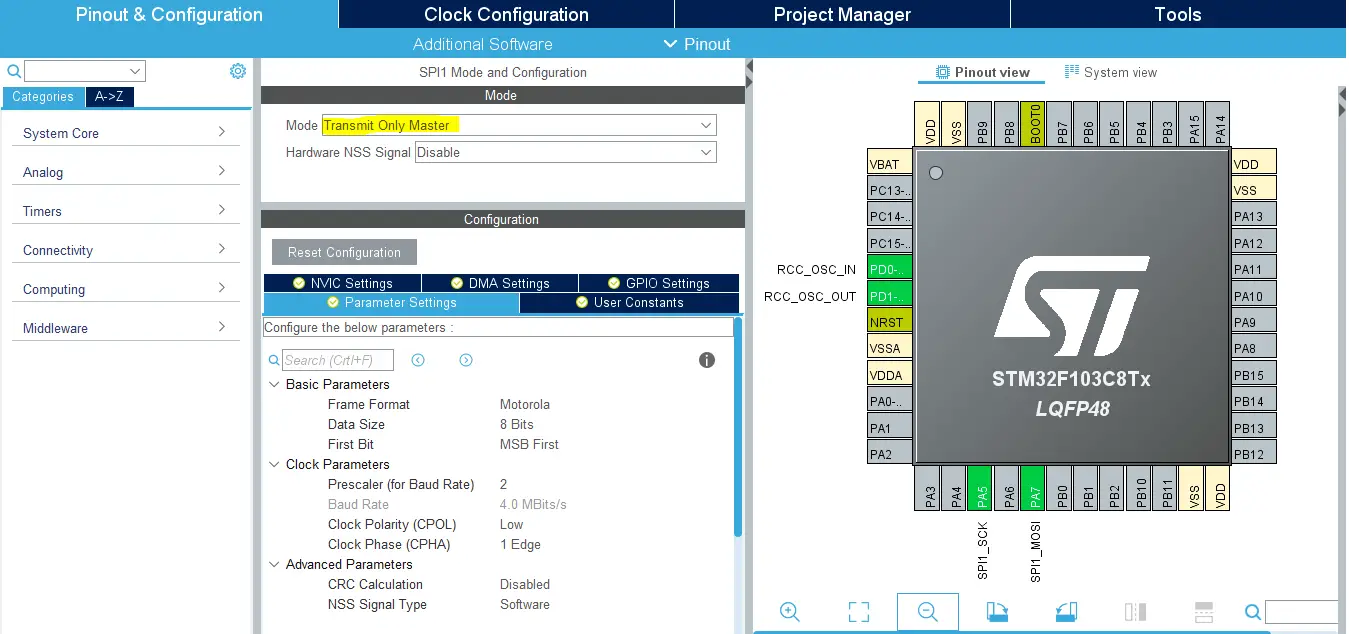
Step6: Enable Any SPI peripheral in any Mode with any Prescaler value (maybe 256)
this step is actually required in order to have the HAL_SPI files generated and added to our project. Because the dot matrix library does use the HAL SPI APIs, so it’s important to have them added to our project by CubeMX.
This step will result in the addition of a function that initializes the SPI peripheral in the main.c source file. But we’ll just delete it as the Dot Matrix library will handle the SPI initialization process. However, the global SPI handler structure (hspix) shouldn’t be deleted.
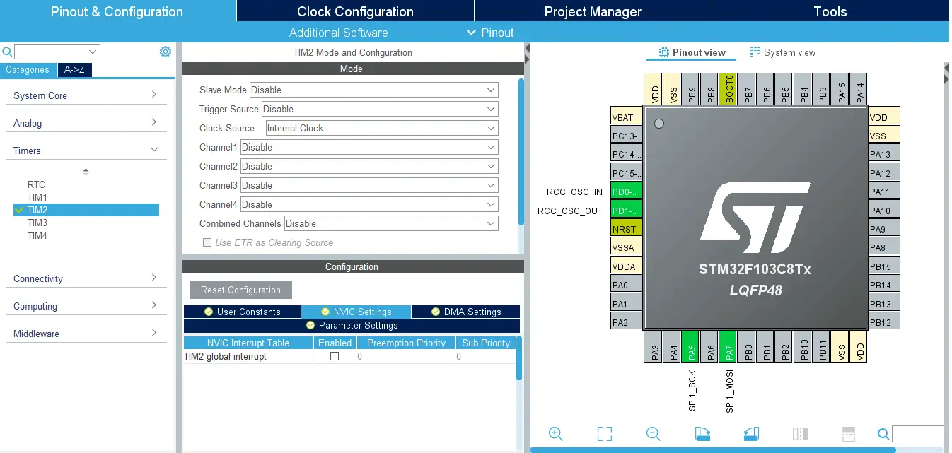
Step7: Enable Any TIMERx module (Even without being used in this lab)
this step is actually required in order to have the HAL_TIMER files generated and added to our project. Because the dot matrix library does use the HAL TIMER APIs, so it’s important to have them added to our project by CubeMX.
This step will result in the addition of a function that initializes the TIMER peripheral in the main.c source file. But we’ll just delete it as the Dot Matrix library will handle the SPI initialization process. as well as the global TIMER handler structure (htimx).
Step8: Generate The Initialization Code & Open The Project In Your IDE
Step9: Add the ECUAL/ DOT_MATRIX driver files to your project
Follow This Tutorial which shows you How To Add Any ECUAL Driver To An STM32 Project step-by-step.

You basically right-click the project name in the IDE’s navigator and choose to create a new > source folder. And name it ECUAL and go to the GitHub repo, download the files and copy the “DOT_MATRIX” folder and back to the IDE, right-click on the ECUAL and paste the library into it.
Now, we can start developing our application in the main.c source file.
Here Are The Drivers Configurations I Used For This LAB
DOT_MATRIX_cfg.c File
|
1 2 3 4 5 6 7 8 9 10 11 12 |
const DOT_MATRIX_CfgType DOT_MATRIX_CfgParam[DOT_MATRIX_UNITS] = { // DOT_MATRIX 1 Configurations { GPIOB, GPIO_PIN_0, 75, /* Scroll Speed*/ 1, /* Number Of Cascaded Devices*/ 8, /* Brightness Level */ STATIC_MODE } }; |
DOT_MATRIX.h File
|
1 2 3 4 5 6 7 8 9 10 11 12 13 |
// The Number OF Separate DOT MATRIX Units (Whether Single or Cascaded) To Be Used In The Project #define DOT_MATRIX_UNITS 1 // The Matrix Units Count Of The Longest Cascaded String In The System #define MAX_CASCADED_NUM 1 // DOT Matrix SPI Options #define DOT_MATRIX_SPI SPI1 // DOT Matrix Timer Base Options #define MATRIX_TIMER_EN 0 #define MATRIX_TIMER TIM4 #define MATRIX_TIMER_CLK 72 #define MATRIX_TIME_BASE 1 |
Here is The Application Code For This LAB (main.c)
|
1 2 3 4 5 6 7 8 9 10 11 12 13 14 15 16 17 18 19 20 21 22 23 24 25 26 27 28 29 30 31 |
#include "main.h" #include "../ECUAL/DOT_MATRIX/DOT_MATRIX.h" #define MATRIX_DISPLAY_UNIT1 0 SPI_HandleTypeDef hspi1; void SystemClock_Config(void); static void MX_GPIO_Init(void); int main(void) { uint8_t C = 48; HAL_Init(); SystemClock_Config(); MX_GPIO_Init(); DOT_MATRIX_Init(&hspi1); MATRIX_CLEAR(MATRIX_DISPLAY_UNIT1); while (1) { MATRIX_Write_Char(MATRIX_DISPLAY_UNIT1, C++); if(C == 58) { C = 48; } HAL_Delay(1000); } } |
Download The STM32 MAX7219 Dot Matrix (1 Independent unit) Example – LAB58
The Result For This LAB Testing (Video)
STM32 MAX7219 Dot Matrix Display (2 Independent) – LAB
| LAB Number | 59 |
| LAB Title | STM32 With 2 Independent Dot Matrix Display Units (1 Module Per Unit, No Cascading) – Static Mode |
- Set up a new project as usual with a system clock @ 72MHz (STM32F103C8T6) or whatever your uC board supports
- Enable Any SPI module (any mode, doesn’t matter) in CubeMX
- Add the ECUAL / DOT_MATRIX driver files to our project. As shown here
- Configure 2 Dot Matrix instances in DOT_MATRIX_cfg.c file
- Initialize the Dot Matrix in the main function, create an up-counting & down-counting counter variables and send the characters to the first & second dot matrix display units (static mode)
And now, let’s build this system step-by-step
Step1: Open CubeMX & Create New Project
Step2: Choose The Target MCU & Double-Click Its Name
STM32F103C8T6 (the one I’ll be using) or any other STM32 part you’ve got
Step3: Go To The RCC Clock Configuration
Step4: Set The System Clock To Be 72MHz or whatever your uC board supports
Step6: Enable Any SPI peripheral in any Mode with any Prescaler value (maybe 256)
this step is actually required in order to have the HAL_SPI files generated and added to our project. Because the dot matrix library does use the HAL SPI APIs, so it’s important to have them added to our project by CubeMX.
This step will result in the addition of a function that initializes the SPI peripheral in the main.c source file. But we’ll just delete it as the Dot Matrix library will handle the SPI initialization process. However, the global SPI handler structure (hspix) shouldn’t be deleted.
Step7: Enable Any TIMERx module (Even without being used in this lab)
this step is actually required in order to have the HAL_TIMER files generated and added to our project. Because the dot matrix library does use the HAL TIMER APIs, so it’s important to have them added to our project by CubeMX.
This step will result in the addition of a function that initializes the TIMER peripheral in the main.c source file. But we’ll just delete it as the Dot Matrix library will handle the SPI initialization process. as well as the global TIMER handler structure (htimx).
Step8: Generate The Initialization Code & Open The Project In Your IDE
Step9: Add the ECUAL/ DOT_MATRIX driver files to your project
Follow This Tutorial which shows you How To Add Any ECUAL Driver To An STM32 Project step-by-step.
You basically right-click the project name in the IDE’s navigator and choose to create a new > source folder. And name it ECUAL and go to the GitHub repo, download the files and copy the “DOT_MATRIX” folder and back to the IDE, right-click on the ECUAL and paste the library into it.
Now, we can start developing our application in the main.c source file.
Here Are The Drivers Configurations I Used For This LAB
DOT_MATRIX_cfg.c File
|
1 2 3 4 5 6 7 8 9 10 11 12 13 14 15 16 17 18 19 20 21 |
const DOT_MATRIX_CfgType DOT_MATRIX_CfgParam[DOT_MATRIX_UNITS] = { // DOT_MATRIX Display Unit1 Configurations { GPIOB, GPIO_PIN_0, 75, /* Scroll Speed*/ 1, /* Number Of Cascaded Devices*/ 8, /* Brightness Level */ STATIC_MODE }, // DOT_MATRIX Display Unit2 Configurations { GPIOB, GPIO_PIN_1, 75, /* Scroll Speed*/ 1, /* Number Of Cascaded Devices*/ 8, /* Brightness Level */ STATIC_MODE } }; |
DOT_MATRIX.h File
|
1 2 3 4 5 6 7 8 9 10 11 12 13 |
// The Number OF Separate DOT MATRIX Units (Whether Single or Cascaded) To Be Used In The Project #define DOT_MATRIX_UNITS 2 // The Matrix Units Count Of The Longest Cascaded String In The System #define MAX_CASCADED_NUM 1 // DOT Matrix SPI Options #define DOT_MATRIX_SPI SPI1 // DOT Matrix Timer Base Options #define MATRIX_TIMER_EN 0 #define MATRIX_TIMER TIM4 #define MATRIX_TIMER_CLK 72 #define MATRIX_TIME_BASE 1 |
Here is The Application Code For This LAB (main.c)
|
1 2 3 4 5 6 7 8 9 10 11 12 13 14 15 16 17 18 19 20 21 22 23 24 25 26 27 28 29 30 31 32 33 34 35 36 37 38 39 |
#include "main.h" #include "../ECUAL/DOT_MATRIX/DOT_MATRIX.h" #define MATRIX_DISPLAY_UNIT1 0 #define MATRIX_DISPLAY_UNIT2 1 SPI_HandleTypeDef hspi1; TIM_HandleTypeDef htim4; void SystemClock_Config(void); static void MX_GPIO_Init(void); int main(void) { uint8_t C = 48, D = 57; HAL_Init(); SystemClock_Config(); MX_GPIO_Init(); DOT_MATRIX_Init(&hspi1); MATRIX_CLEAR(MATRIX_DISPLAY_UNIT1); MATRIX_CLEAR(MATRIX_DISPLAY_UNIT2); while (1) { MATRIX_Write_Char(MATRIX_DISPLAY_UNIT1, C++); MATRIX_Write_Char(MATRIX_DISPLAY_UNIT2, D--); if(C == 58) { C = 48; } if(D == 47) { D = 57; } HAL_Delay(1000); } } |
Download The STM32 MAX7219 Dot Matrix (2 Independent units) Example – LAB59
The Result For This LAB Testing (Video)
STM32 MAX7219 Dot Matrix Display Scrolling (2 cascaded) – LAB
| LAB Number | 60 |
| LAB Title | STM32 With 1 Independent Dot Matrix Display Unit (2 Cascaded Modules) – Scrolling Mode |
- Set up a new project as usual with a system clock @ 72MHz (STM32F103C8T6) or whatever your uC board supports
- Enable Any SPI module (any mode, doesn’t matter) in CubeMX
- Add the ECUAL / DOT_MATRIX driver files to our project. As shown here
- Configure 1 Dot Matrix instances in DOT_MATRIX_cfg.c file
- Initialize the Dot Matrix in the main function, create a text message buffer and send it to be displayed (scrolling mode)
And now, let’s build this system step-by-step
Step1: Open CubeMX & Create New Project
Step2: Choose The Target MCU & Double-Click Its Name
STM32F103C8T6 (the one I’ll be using) or any other STM32 part you’ve got
Step3: Go To The RCC Clock Configuration
Step4: Set The System Clock To Be 72MHz or whatever your uC board supports
Step5: Enable Any SPI peripheral in any Mode with any Prescaler value (maybe 256)
this step is actually required in order to have the HAL_SPI files generated and added to our project. Because the dot matrix library does use the HAL SPI APIs, so it’s important to have them added to our project by CubeMX.
This step will result in the addition of a function that initializes the SPI peripheral in the main.c source file. But we’ll just delete it as the Dot Matrix library will handle the SPI initialization process. However, the global SPI handler structure (hspix) shouldn’t be deleted.
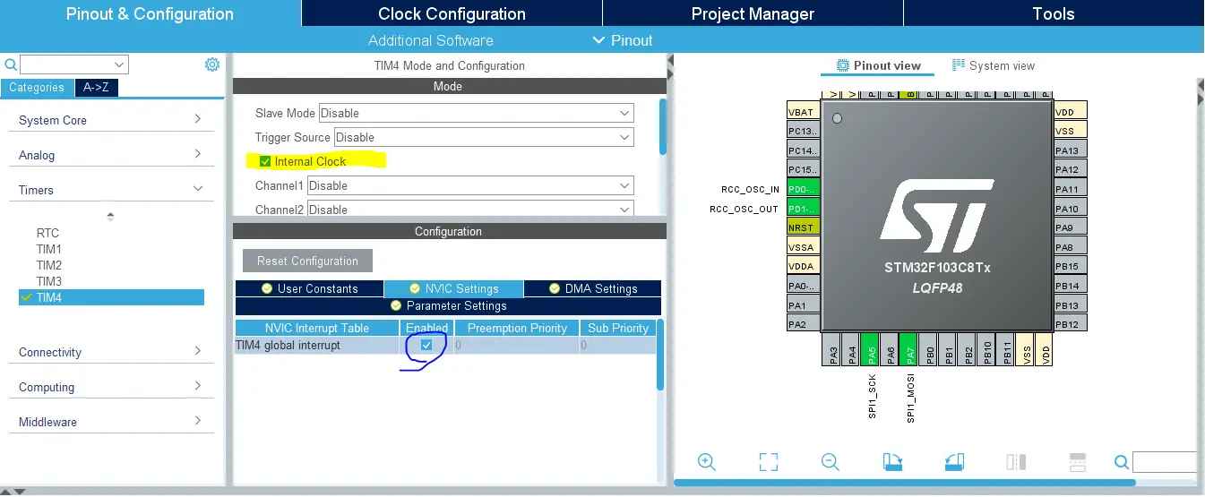
Step6: Enable Any TIMERx module + Enable its NVIC interrupt
this step is actually required in order to have the HAL_TIMER files generated and added to our project. Because the dot matrix library does use the HAL TIMER APIs, so it’s important to have them added to our project by CubeMX.
This step will result in the addition of a function that initializes the TIMER peripheral in the main.c source file. But we’ll just delete it as the Dot Matrix library will handle the SPI initialization process. However, you shouldn’t delete the global TIMER handler structure (htimx), just pass it to the init function as it’s being used by my library.
Step7: Generate The Initialization Code & Open The Project In Your IDE
Step8: Add the ECUAL/ DOT_MATRIX driver files to your project
Follow This Tutorial which shows you How To Add Any ECUAL Driver To An STM32 Project step-by-step.
You basically right-click the project name in the IDE’s navigator and choose to create a new > source folder. And name it ECUAL and go to the GitHub repo, download the files and copy the “DOT_MATRIX” folder and back to the IDE, right-click on the ECUAL and paste the library into it.
Now, we can start developing our application in the main.c source file.
Here Are The Drivers Configurations I Used For This LAB
DOT_MATRIX_cfg.c File
|
1 2 3 4 5 6 7 8 9 10 11 12 |
const DOT_MATRIX_CfgType DOT_MATRIX_CfgParam[DOT_MATRIX_UNITS] = { // DOT_MATRIX Display Unit1 Configurations { GPIOB, GPIO_PIN_0, 75, /* Scroll Speed*/ 2, /* Number Of Cascaded Devices*/ 8, /* Brightness Level */ SCROLL_MODE } }; |
DOT_MATRIX.h File
|
1 2 3 4 5 6 7 8 9 10 11 12 13 |
// The Number OF Separate DOT MATRIX Units (Whether Single or Cascaded) To Be Used In The Project #define DOT_MATRIX_UNITS 1 // The Matrix Units Count Of The Longest Cascaded String In The System #define MAX_CASCADED_NUM 2 // DOT Matrix SPI Options #define DOT_MATRIX_SPI SPI1 // DOT Matrix Timer Base Options #define MATRIX_TIMER_EN 1 #define MATRIX_TIMER TIM4 #define MATRIX_TIMER_CLK 72 #define MATRIX_TIME_BASE 1 |
Here is The Application Code For This LAB (main.c)
|
1 2 3 4 5 6 7 8 9 10 11 12 13 14 15 16 17 18 19 20 21 22 23 24 25 26 27 28 29 30 31 |
#include "main.h" #include "../ECUAL/DOT_MATRIX/DOT_MATRIX.h" #define MATRIX_DISPLAY_UNIT1 0 SPI_HandleTypeDef hspi1; TIM_HandleTypeDef htim4; void SystemClock_Config(void); static void MX_GPIO_Init(void); int main(void) { char MSG[] = " DeepBlueMbedded.com "; HAL_Init(); SystemClock_Config(); MX_GPIO_Init(); DOT_MATRIX_Init_TMR(&hspi1, &htim4); MATRIX_DisplayMessage(MATRIX_DISPLAY_UNIT1, MSG, sizeof(MSG)); while (1) { } } void HAL_TIM_PeriodElapsedCallback(TIM_HandleTypeDef *htim) { MATRIX_TMR_OVF_ISR(htim); } |
Download The STM32 MAX7219 Dot Matrix Scrolling (2 Cascaded) Example – LAB60
The Result For This LAB Testing (Video)
STM32 MAX7219 Dot Matrix Display Scrolling (2 cascaded) + Speed Control
| LAB Number | 61 |
| LAB Title | STM32 With 1 Independent Dot Matrix Display Unit (2 Cascaded Modules) – Scrolling Mode + Manual Scroll Speed Control |
- Set up a new project as usual with a system clock @ 72MHz (STM32F103C8T6) or whatever your uC board supports
- Enable Any SPI module (any mode, doesn’t matter) in CubeMX
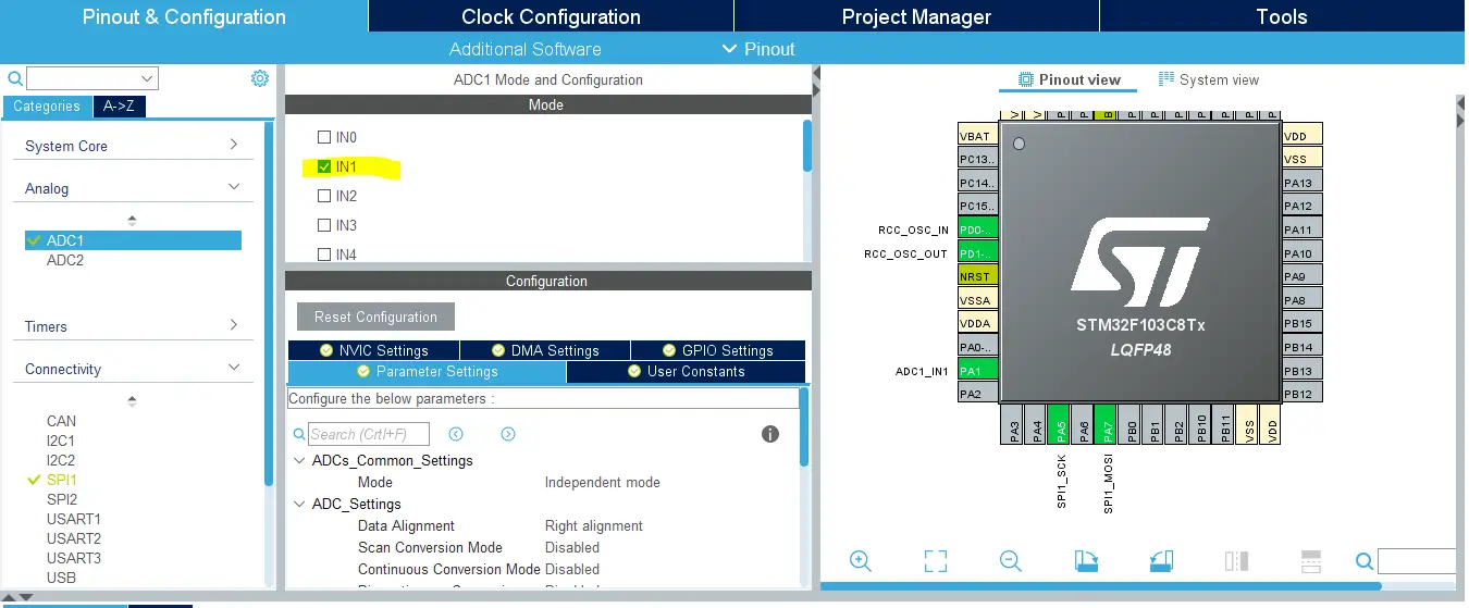
- Enable Any ADC Channel (For Potentiometer) in CubeMX
- Add the ECUAL / DOT_MATRIX driver files to our project. As shown here
- Configure 1 Dot Matrix instances in DOT_MATRIX_cfg.c file
- Initialize the Dot Matrix in the main function, create a text message buffer and send it to be displayed (scrolling mode) + Read the ADC & Use the signal to control the speed of scrolling with the corresponding function
And now, let’s build this system step-by-step
Step1: Open CubeMX & Create New Project
Step2: Choose The Target MCU & Double-Click Its Name
STM32F103C8T6 (the one I’ll be using) or any other STM32 part you’ve got
Step3: Go To The RCC Clock Configuration
Step4: Set The System Clock To Be 72MHz or whatever your uC board supports
Step5: Enable Any SPI peripheral in any Mode with any Prescaler value (maybe 256)
this step is actually required in order to have the HAL_SPI files generated and added to our project. Because the dot matrix library does use the HAL SPI APIs, so it’s important to have them added to our project by CubeMX.
This step will result in the addition of a function that initializes the SPI peripheral in the main.c source file. But we’ll just delete it as the Dot Matrix library will handle the SPI initialization process. However, the global SPI handler structure (hspix) shouldn’t be deleted.
Step6: Enable Any TIMERx module + Enable its NVIC interrupt
this step is actually required in order to have the HAL_TIMER files generated and added to our project. Because the dot matrix library does use the HAL TIMER APIs, so it’s important to have them added to our project by CubeMX.
This step will result in the addition of a function that initializes the TIMER peripheral in the main.c source file. But we’ll just delete it as the Dot Matrix library will handle the SPI initialization process. However, you shouldn’t delete the global TIMER handler structure (htimx), just pass it to the init function as it’s being used by my library.
Step7: Enable Any ADCx / CHx To Be Used For the Potentiometer (for speed control)
Step8: Generate The Initialization Code & Open The Project In Your IDE
Step9: Add the ECUAL/ DOT_MATRIX driver files to your project
Follow This Tutorial which shows you How To Add Any ECUAL Driver To An STM32 Project step-by-step.
You basically right-click the project name in the IDE’s navigator and choose to create a new > source folder. And name it ECUAL and go to the GitHub repo, download the files and copy the “DOT_MATRIX” folder and back to the IDE, right-click on the ECUAL and paste the library into it.
Now, we can start developing our application in the main.c source file.
Here Are The Drivers Configurations I Used For This LAB
DOT_MATRIX_cfg.c File
|
1 2 3 4 5 6 7 8 9 10 11 12 |
const DOT_MATRIX_CfgType DOT_MATRIX_CfgParam[DOT_MATRIX_UNITS] = { // DOT_MATRIX Display Unit1 Configurations { GPIOB, GPIO_PIN_0, 75, /* Scroll Speed*/ 2, /* Number Of Cascaded Devices*/ 8, /* Brightness Level */ SCROLL_MODE } }; |
DOT_MATRIX.h File
|
1 2 3 4 5 6 7 8 9 10 11 12 13 |
// The Number OF Separate DOT MATRIX Units (Whether Single or Cascaded) To Be Used In The Project #define DOT_MATRIX_UNITS 1 // The Matrix Units Count Of The Longest Cascaded String In The System #define MAX_CASCADED_NUM 2 // DOT Matrix SPI Options #define DOT_MATRIX_SPI SPI1 // DOT Matrix Timer Base Options #define MATRIX_TIMER_EN 1 #define MATRIX_TIMER TIM4 #define MATRIX_TIMER_CLK 72 #define MATRIX_TIME_BASE 1 |
Here is The Application Code For This LAB (main.c)
|
1 2 3 4 5 6 7 8 9 10 11 12 13 14 15 16 17 18 19 20 21 22 23 24 25 26 27 28 29 30 31 32 33 34 35 36 37 38 39 40 41 42 43 44 |
#include "main.h" #include "../ECUAL/DOT_MATRIX/DOT_MATRIX.h" #define MATRIX_DISPLAY_UNIT1 0 SPI_HandleTypeDef hspi1; TIM_HandleTypeDef htim4; ADC_HandleTypeDef hadc1; void SystemClock_Config(void); static void MX_GPIO_Init(void); static void MX_ADC1_Init(void); int main(void) { char MSG[] = " DeepBlueMbedded.com "; uint16_t AD_RES = 0, Speed = 1; HAL_Init(); SystemClock_Config(); MX_GPIO_Init(); MX_ADC1_Init(); DOT_MATRIX_Init_TMR(&hspi1, &htim4); MATRIX_DisplayMessage(MATRIX_DISPLAY_UNIT1, MSG, sizeof(MSG)); while (1) { HAL_ADC_Start(&hadc1); HAL_ADC_PollForConversion(&hadc1, 1); AD_RES = HAL_ADC_GetValue(&hadc1); Speed = AD_RES>>4; if(Speed >= 1) { MATRIX_SCROLL_SetSpeed(MATRIX_DISPLAY_UNIT1, (AD_RES>>4)); } HAL_Delay(10); } } void HAL_TIM_PeriodElapsedCallback(TIM_HandleTypeDef *htim) { MATRIX_TMR_OVF_ISR(htim); } |
Download The STM32 MAX7219 Dot Matrix Scrolling (2 Cascaded) + Speed Control Example – LAB61
The Result For This LAB Testing (Video)
Did you find this helpful? If yes, please consider supporting this work and sharing these tutorials!
Stay tuned for the upcoming tutorials and don’t forget to SHARE these tutorials. And consider SUPPORTING this work to keep publishing free content just like this!
| Previous Tutorial | Tutorial 43 | Next Tutorial | |||||
Im testing “Lab 60” and works fine. Do you know how i can rotate 90 degrees CCW the scrolling text direction? Im using 4 cascaded matrix and can´t show correctly the scrolling text (I don´t want to cut the 4 matrix board to solder one by one). Thank you for your amazing work! Adrián from Buenos Aires, Argentina.
hello sir, i have an idea about using the matrix display with the PIR based motion detector sensor that means when a person has been detected the, the 8*32 matrix scrolling display will show us the message ‘welcome to this place’ . But we I don’t know whether to start from please help!