| Previous Tutorial | Tutorial 26 | Next Tutorial | |||||
| STM32 LM35 Temperature Sensor Interfacing | |||||||
| STM32 Course Home Page ???? | |||||||
In this article, we’ll create a simple project for STM32 LM35 temperature sensor interfacing with ADC. It’ll also include an LCD screen to display the temperature. You’ll also learn how to add and configure the ECUAL drivers, it was described before in a previous tutorial, but today will be another practice example to see how to build portable high-level application firmware.
[toc]
Required Components For LABs
All the example code/LABs/projects in the course are going to be done using those boards below.
- Nucleo32-L432KC (ARM Cortex-M4 @ 80MHz) or (eBay)
- Blue Pill STM32-F103 (ARM Cortex-M3 @ 72MHz) or (eBay)
- ST-Link v2 Debugger or (eBay)
| QTY | Component Name | ???? Amazon.com | ???? eBay.com |
| 2 | BreadBoard | Amazon | eBay |
| 1 | LEDs Kit | Amazon Amazon | eBay |
| 1 | Resistors Kit | Amazon Amazon | eBay |
| 1 | Capacitors Kit | Amazon Amazon | eBay & eBay |
| 2 | Jumper Wires Pack | Amazon Amazon | eBay & eBay |
| 1 | 9v Battery or DC Power Supply | Amazon Amazon Amazon | eBay |
| 1 | Micro USB Cable | Amazon | eBay |
| 1 | Push Buttons | Amazon Amazon | eBay |
| 1 | LM35 Temperature Sensor | Amazon | eBay |
| 1 | Alphanumeric LCD Module | Amazon | eBay |
| 1 | USB-TTL Converter or FTDI Chip | Amazon Amazon | eBay eBay |
★ Check The Full Course Complete Kit List
Some Extremely Useful Test Equipment For Troubleshooting:
- My Digital Storage Oscilloscope (DSO): Siglent SDS1104 (on Amazon.com) (on eBay)
- FeelTech DDS Function Generator: KKMoon FY6900 (on Amazon.com) (on eBay)
- Logic Analyzer (on Amazon.com) (on eBay)
Affiliate Disclosure: When you click on links in this section and make a purchase, this can result in this site earning a commission. Affiliate programs and affiliations include, but are not limited to, the eBay Partner Network (EPN) and Amazon.com.
STM32 LM35 Temperature Sensor Interfacing
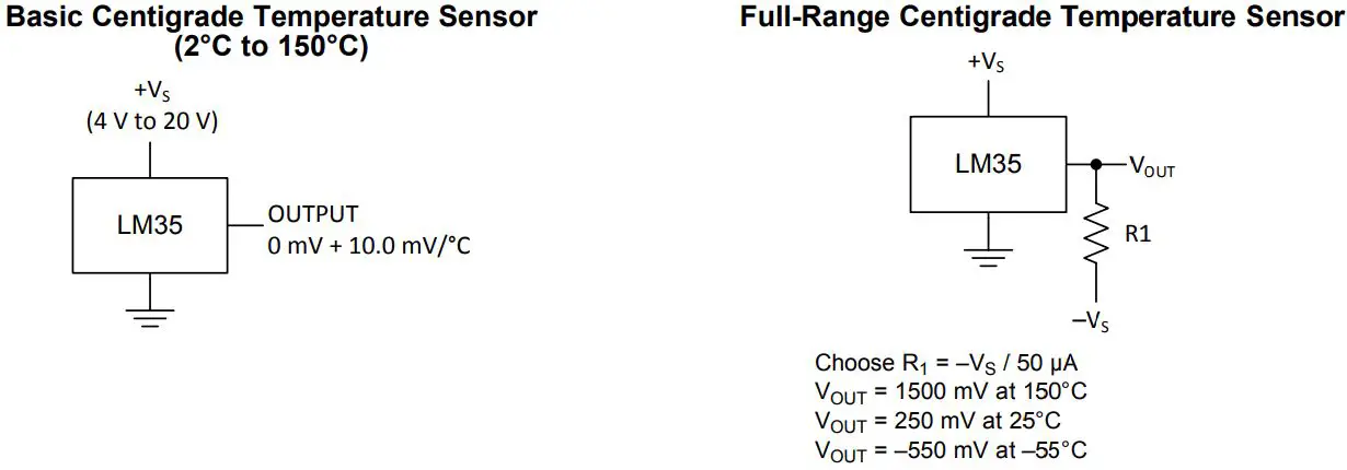
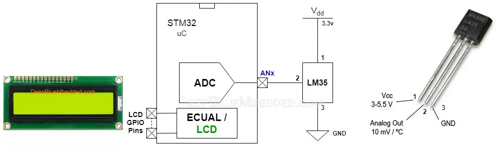
The LM35 series are precision integrated-circuit temperature devices with an output voltage linearly proportional to the Centigrade temperature. It has a linear + 10-mV/°C Scale Factor. Which means you’ll have to measure its output voltage and divide it by 0.01 to get the temperature reading in °C, that’s all.
The LM35 temperature sensor can be used in a couple of configurations. The basic one is the full positive temperature range (from 2°C up to +150°C). And the full range that can go below zero degrees (from -55°C up to +150°C). The basic configuration requires no external components besides the LM35 itself, and the full range configuration requires an additional resistor which can be calculated using the formula in the diagram below.
It’s a matter of configuring the ADC and triggering it to convert the corresponding channel and read the result and use the linear equation above to find out the temperature. However, we need to make our application code portable and configurable so it doesn’t call a specific channel or ADC instance, and that’s what I’ve done in the ECUAL/LM35 driver. Let’s see what’s inside of it, how it works, and how to configure and use it. And before that, if you need a solid and basic introduction to the LM35 sensor interfacing, you can check out This LM35 Interfacing Tutorial.
STM32 LM35 ECUAL Driver
In this section, I’ll describe the LM35 driver components and how to configure and add it to your projects.
The ECUAL / LM35 Driver Files
The LM35 driver consists of the following files:
|
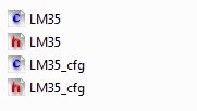 |
It can be found in the course’s repo on GitHub.
You’ll need only to modify the configuration files. The source code for this driver is found in (LM35.c) and to use it you’ll include the header (LM35.h). Therefore, I’ll write here the code listing for the LM35_cfg.c file.
LM_cfg.c File
|
1 2 3 4 5 6 7 8 9 10 11 |
#include "LM35.h" const LM35_CfgType LM35_CfgParam[SENSORS_NUM] = { // LM35 Sensor 1 Configurations { GPIOA, ADC1, ADC_CHANNEL_7 } }; |
The SENSORS_NUM is defined to 1, so the configuration initialization above creates an instance of the LM35_cfg that is connected to an analog input pin on GPIOA, associated with ADC1 peripheral, and the channel number is 7. That’s the instantiation statement in order to configure your sensor driver code.
The ECUAL / LM35 Driver Configurations
You can configure the following parameters with this driver version:
SENSORS_NUM can be defined as 1, 2, 3, or whatever number you need. This represents how many LM35 sensors are there in your system, in case you’re using multiple sensors. The default value is 1.
The GPIOx port represents the GPIO port that the analog input pin belongs to. You have the freedom to hook the sensor to any analog pin on your microcontroller.
ADC_Instance you can assign ADC1, ADC2, or whatever ADCx peripheral is dedicated to the channel you’ve chosen to hook your sensor to.
Lastly, the ADC_Channel_Num is the ADC analog input pin channel number.
The ECUAL / LM35 Driver APIs For Application
The application layer will include the “LM35.h” header file of the driver. And therefore, it can access the available APIs. There are basically 2 functions in the source code of this driver as mentioned down below.
|
1 2 |
void LM35_Init(uint16_t LM35_Instance); float LM35_Read(uint16_t LM35_Instance); |
Obviously, the init function initialized the LM35 sensor line. It takes the number of the sensor as a parameter. If you’re using only one LM35 sensor, then pass 0 to this function. Otherwise, you’ll need to pass the index of the addressed sensor instance.
The LM35_Read function does a lot of things actually. It selects the analog sensor line from the ADC configurations and triggers an A/D conversion and takes the ADC result, converts it to temperature as a floating-point number, and returns the result at the end. The input parameter is the number of the LM35 sensor that you want to read, just in case you’re using multiple sensors in the system.
The ECUAL / LM35 Driver Instantiation
In order to instantiate an LM35 sensor line, you’ll have to open the LM35_cfg.c file and add your configurations. Let’s assume I’ve got 1 LM35 sensor and I want to hook it to the pin A5 which is associated with ADC1 peripheral. Here is what should be written in the cfg.c file.
|
1 2 3 4 5 6 7 8 9 |
const LM35_CfgType LM35_CfgParam[SENSORS_NUM] = { // LM35 Sensor 1 Configurations { GPIOA, ADC1, ADC_CHANNEL_5 } }; |
Another example: let’s assume my system does have 2 LM35 sensors, the first of which is going to be connected to analog channel A2, and the other one to channel A6, both are associated with ADC1. Here is what should be written in the cfg.c file.
|
1 2 3 4 5 6 7 8 9 10 11 12 13 14 15 |
const LM35_CfgType LM35_CfgParam[SENSORS_NUM] = { // LM35 Sensor 1 Configurations { GPIOA, ADC1, ADC_CHANNEL_2 }, // LM35 Sensor 2 Configurations { GPIOA, ADC1, ADC_CHANNEL_6 } }; |
How To Add The ECUAL / LM35 Driver To Your Project
Please, refer to This Tutorial (How To Add ECUAL Drivers To Your STM32 Projects) in which I’ve shown the exact step-by-step procedure in order to add any ECUAL driver to your project. The exact same steps are still the same, however, that tutorial shows how to add the LCD driver but it’s the same steps anyway. And in today’s LAB, we’ll need to add that LCD driver as well, so it’s highly recommended.
STM32 Light Sensor Project – LAB21
| LAB Number | 21 |
| LAB Title | STM32 LM35 Temperature Sensor Interfacing + LCD |
- Set up a new project as usual with system clock @ 72MHz
- Set up An Analog Input Pin (Channel 7) In single Conversion Mode (The LDR Pin)
- Set up timer2 in PWM mode with output on channel 1 (The LED Pin)
Here is The Connection Diagram For This LAB
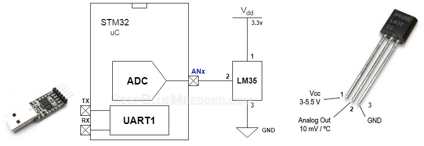
It Can Also Go This Way & Implement It Without An LCD But Use Serial Port To Print The Result
STM32 LM35 Example
In this LAB project, we’ll initialize the LM35 sensor, the LCD display, and continuously read the sensor and update the display with the temperature value. The application firmware itself is really easy once you’ve included the necessary drivers and configured everything as it should be.
And now, let’s build this system step-by-step
Step1: Open CubeMX & Create New Project
Step2: Choose The Target MCU & Double-Click Its Name
Step3: Set The RCC External Clock Source
Step4: Go To The Clock Configuration
Step5: Set The System Clock To Be 72MHz
The ADC peripherals will be assigned a default clock of 12MHz that you can optionally increase to a maximum of 14MHz. But we won’t do that in this example.
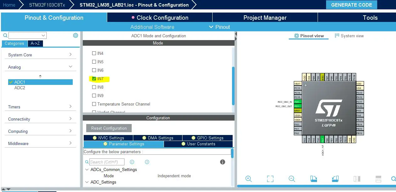
Step6: Enable The Analog Channel To Be Used (AN7)
This step seems to be redundant as the LM35 driver actually configures the ADC module and enables that channel which overrides any configurations done here in CubeMX. However, this step is mandatory as it makes CubeMX generate the ADC_HAL files which are being used by the driver itself. So you need at least to enable one channel just to have those files generated and included in the project directory.
Step7: Name & Generate The Project Initialization Code For CubeIDE or The IDE You’re Using
Step8: Add The ECUAL LCD, LM35 Drivers As Well As The util files
The exact steps to add the drivers are illustrated in This Tutorial as mentioned before.
The util folder includes some utility files for software delay functions and stuff like that.
Here is The Application Code For This LAB (main.c)
|
1 2 3 4 5 6 7 8 9 10 11 12 13 14 15 16 17 18 19 20 21 22 23 24 25 26 27 28 29 30 31 |
#include "main.h" #include "stdio.h" #include "../ECUAL/LCD16x2/LCD16x2.h" #include "../ECUAL/LM35/LM35.h" void SystemClock_Config(void); static void MX_GPIO_Init(void); int main(void) { float Temp = 0; uint8_t MSG[16] = {0}; HAL_Init(); SystemClock_Config(); MX_GPIO_Init(); LCD_Init(); LCD_Clear(); LCD_Set_Cursor(1, 1); LCD_Write_String("Temperature Is:"); LM35_Init(0); while (1) { Temp = LM35_Read(0); sprintf(MSG, "%.3f C", Temp); LCD_Set_Cursor(2, 1); LCD_Write_String(MSG); HAL_Delay(100); } } |
Download The STM32 LM35 Temperature Sensor Project LAB21
Note That: the floating-point numbers formatting may not be enabled in the IDE tools by default. Therefore, you’ll need to enable that manually in order to be able to use the sprintf() function to print formatted float variables. Just do the following
Open project properties by right-clicking on its name in the IDE project files navigator > C/C++ Build > Settings > Tool Settings > check the option “use float with printf”. That’s all!
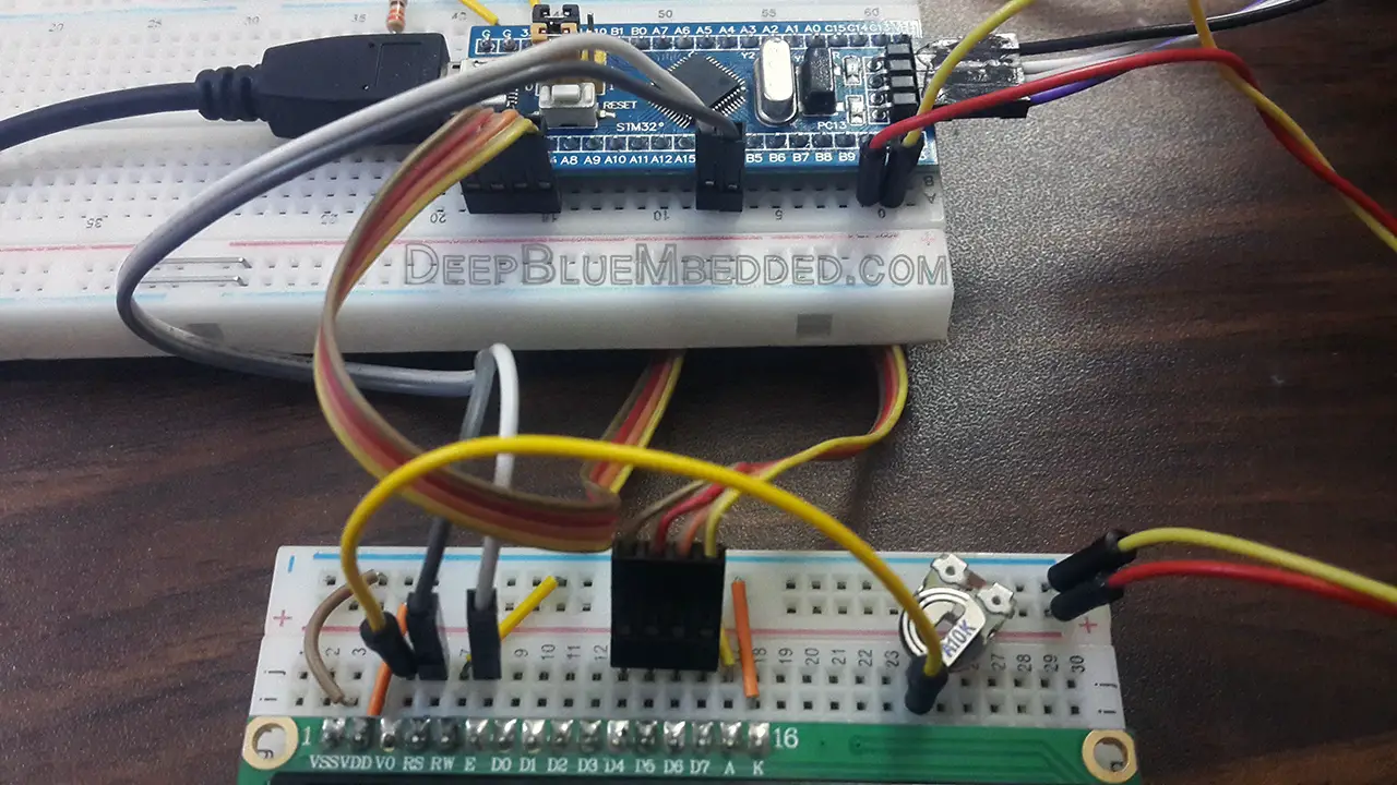
The LAB Connections
LM35 Temperature Sensor Connection
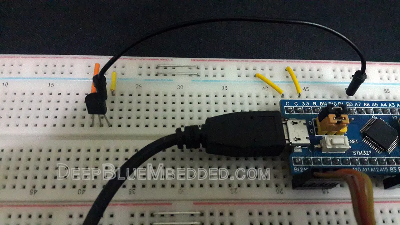
LCD Connection
The Result For LAB Testing (video)
STM32 LM35 Driver Multi-Sensor Support
As I’ve mentioned earlier that this ECUAL LM35 driver can be used to instantiate multiple LM35 sensors with different channels using the configurations files. For example, here is a typical configuration structure for a project that will have 2 LM35 sensors working independently.
LM35_cfg.c
|
1 2 3 4 5 6 7 8 9 10 11 12 13 14 15 |
const LM35_CfgType LM35_CfgParam[SENSORS_NUM] = { // LM35 Sensor 1 Configurations { GPIOA, ADC1, ADC_CHANNEL_2 }, // LM35 Sensor 2 Configurations { GPIOA, ADC1, ADC_CHANNEL_6 } }; |
And here is a typical application example for initializing and reading both sensors.
main.c
|
1 2 3 4 5 6 7 8 9 10 11 12 13 14 15 16 17 18 19 20 21 22 23 24 25 26 27 28 29 30 31 32 33 |
#include "main.h" #include "stdio.h" #include "../ECUAL/LM35/LM35.h" ADC_HandleTypeDef hadc1; UART_HandleTypeDef huart1; void SystemClock_Config(void); static void MX_GPIO_Init(void); static void MX_USART1_UART_Init(void); int main(void) { float Temp1 = 0, Temp2 = 0; uint8_t MSG[40] = {0}; HAL_Init(); SystemClock_Config(); MX_GPIO_Init(); MX_USART1_UART_Init(); LM35_Init(0); LM35_Init(1); while (1) { Temp1 = LM35_Read(0); Temp2 = LM35_Read(1); sprintf(MSG, "Temp = %.3f , %.3f\r\n", Temp1, Temp2); HAL_UART_Transmit(&huart1, MSG, sizeof(MSG), 100); HAL_Delay(10); } } |
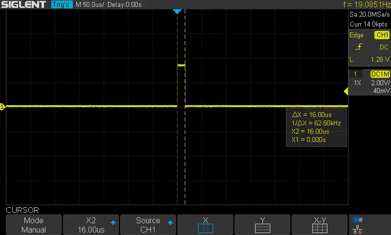
STM32 LM35 Driver Sampling Time
One final test that I’ve also done was to configure the LM35 sensor in normal settings and set the system clock of the Blue Pill (STM32F103C8) @ 72MHz, the ADC @ 12MHz, and using a free GPIO pin. I set the pin HIGH before calling the LM35_Read function and driver the pin LOW after the function return. So as to measure the sampling time for the LM35_Read function. And it was found to be 16µs as you can see on the DSO screen. I can use it safely in any OS-based applications hereafter, so it’s ok any may not seek to optimize it more at least in the near future.
Stay tuned for the upcoming tutorials and don’t forget to SHARE these tutorials. And consider SUPPORTING this work to keep publishing free content just like this!
| Previous Tutorial | Tutorial 26 | Next Tutorial | |||||