| Previous Tutorial | Tutorial 25 | Next Tutorial | |||||
| STM32 LDR Interfacing – Ambient Light Sensor Project | |||||||
| STM32 Course Home Page ???? | |||||||
In this LAB, we’ll create a simple STM32 project using the LDR (light dependent resistor) as a light sensor to sense the ambient light intensity and map it to a PWM duty cycle and get this signal out on an LED. So that the LED brightness increases as the surrounding gets darker.
[toc]
Required Components For LABs
All the example code/LABs/projects in the course are going to be done using those boards below.
- Nucleo32-L432KC (ARM Cortex-M4 @ 80MHz) or (eBay)
- Blue Pill STM32-F103 (ARM Cortex-M3 @ 72MHz) or (eBay)
- ST-Link v2 Debugger or (eBay)
| QTY | Component Name | ???? Amazon.com | ???? eBay.com |
| 2 | BreadBoard | Amazon | eBay |
| 1 | LEDs Kit | Amazon Amazon | eBay |
| 1 | Resistors Kit | Amazon Amazon | eBay |
| 1 | Capacitors Kit | Amazon Amazon | eBay & eBay |
| 2 | Jumper Wires Pack | Amazon Amazon | eBay & eBay |
| 1 | 9v Battery or DC Power Supply | Amazon Amazon Amazon | eBay |
| 1 | Micro USB Cable | Amazon | eBay |
| 1 | Push Buttons | Amazon Amazon | eBay |
| 1 | LDR (Light Dependent Resistor) | Amazon | eBay |
★ Check The Full Course Complete Kit List
Some Extremely Useful Test Equipment For Troubleshooting:
- My Digital Storage Oscilloscope (DSO): Siglent SDS1104 (on Amazon.com) (on eBay)
- FeelTech DDS Function Generator: KKMoon FY6900 (on Amazon.com) (on eBay)
- Logic Analyzer (on Amazon.com) (on eBay)
Affiliate Disclosure: When you click on links in this section and make a purchase, this can result in this site earning a commission. Affiliate programs and affiliations include, but are not limited to, the eBay Partner Network (EPN) and Amazon.com.
STM32 Light Sensor (LDR) Interfacing
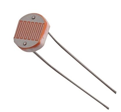
An LDR is a light-dependent resistor, it’s an electronic device that is being used for light intensity sensing applications. The LDR has a relatively low resistance in light, and when the surrounding gets darker the LDR’s resistance significantly increases. Hence, we can make a voltage divider circuit using the LDR and a fixed resistor and use the microcontroller’s ADC to measure the voltage which indicates the resistance value or the light intensity level. An LDR can have a resistance of 5kΩ in daylight, 8kΩ in room light, and up to 2MΩ in darkness.
STM32 Light Sensor Project – LAB20
| LAB Number | 20 |
| LAB Title | STM32 Light Sensor Interfacing With PWM Output LED |
- Set up a new project as usual with system clock @ 72MHz
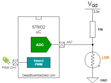
- Set up An Analog Input Pin (Channel 7) In single Conversion Mode (The LDR Pin)
- Set up timer2 in PWM mode with output on channel 1 (The LED Pin)
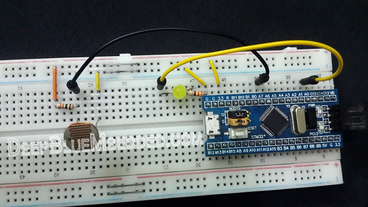
Here is The Connection Diagram For This LAB
STM32 ADC Polling Example
In this LAB project, we’ll estimate the ambient light level and set it as a base level and whenever the light intensity gets lower (surrounding darkens) the LED PWM duty cycle increase and the LED gets brighter.
On power-up, the system estimates the nominal or normal ambient light intensity in your room and set it to be the base for further calculations. That’s why you’ve got to make sure that there is light facing the LDR when powering up the system. Recalibration can be achieved by holding the reset button while providing sufficient light facing the sensor surface.
And now, let’s build this system step-by-step
Step1: Open CubeMX & Create New Project
Step2: Choose The Target MCU & Double-Click Its Name
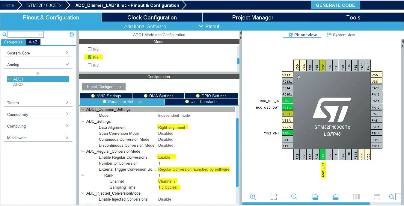
Step3: Configure The ADC1 Peripheral, Enable Channel7 & Set it to be triggered by software
You’ll actually find that the analog channel has these default configurations which happens to be ok for us in this LAB.
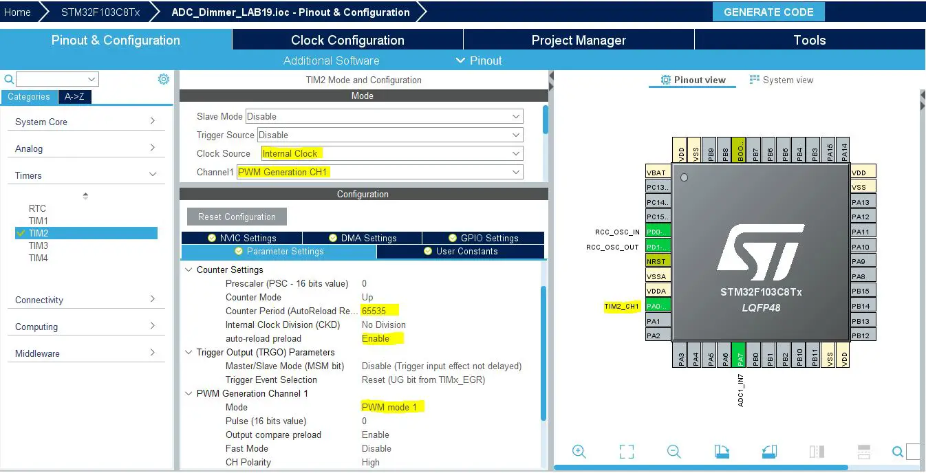
Step4: Configure Timer2 To Operate In PWM Mode With Output On CH1
Step5: Set The RCC External Clock Source
Step6: Go To The Clock Configuration
Step7: Set The System Clock To Be 72MHz
The ADC peripherals will be assigned a default clock of 12MHz that you can optionally increase to a maximum of 14MHz. But we won’t do that in this example.
Step8: Name & Generate The Project Initialization Code For CubeIDE or The IDE You’re Using
Here is The Application Code For This LAB (main.c)
|
1 2 3 4 5 6 7 8 9 10 11 12 13 14 15 16 17 18 19 20 21 22 23 24 25 26 27 28 29 30 31 32 33 34 35 36 37 38 39 40 41 |
#include "main.h" ADC_HandleTypeDef hadc1; TIM_HandleTypeDef htim2; void SystemClock_Config(void); static void MX_GPIO_Init(void); static void MX_ADC1_Init(void); static void MX_TIM2_Init(void); int main(void) { uint16_t AD_RES = 0, Vamb, DC_Multiplier; HAL_Init(); SystemClock_Config(); MX_GPIO_Init(); MX_ADC1_Init(); MX_TIM2_Init(); HAL_TIM_PWM_Start(&htim2, TIM_CHANNEL_1); // Calibrate The ADC On Power-Up For Better Accuracy HAL_ADCEx_Calibration_Start(&hadc1); // Read The Sensor Once To Get The Ambient Level // & Calculate The DutyCycle Multiplier HAL_ADC_Start(&hadc1); HAL_ADC_PollForConversion(&hadc1, 1); Vamb = HAL_ADC_GetValue(&hadc1); DC_Multiplier = 65535/(4096-Vamb); while (1) { // Start ADC Conversion HAL_ADC_Start(&hadc1); // Poll ADC1 Perihperal & TimeOut = 1mSec HAL_ADC_PollForConversion(&hadc1, 1); // Read The ADC Conversion Result & Map It To PWM DutyCycle AD_RES = HAL_ADC_GetValue(&hadc1); TIM2->CCR1 = (AD_RES-Vamb)*DC_Multiplier; HAL_Delay(1); } } |
Download The STM32 Light Sensor (LDR) Project LAB20
The LAB Connections
The Result For LAB Testing (video)
Stay tuned for the upcoming tutorials and don’t forget to SHARE these tutorials. And consider SUPPORTING this work to keep publishing free content just like this!
| Previous Tutorial | Tutorial 25 | Next Tutorial | |||||