
| Previous Tutorial | Tutorial 45 | Next Tutorial | |||||
| STM32 I2C Scanner Example | |||||||
| STM32 Course Home Page ???? | |||||||
In this short tutorial, we’ll be creating an STM32 I2C Scanner example project. To check for the connected slave devices on the I2C bus and report their addresses over UART to our PC.
The I2C Scanner example is a very common Arduino sketch example to scan the I2C bus for available devices and get their addresses (if found). That can be useful if you don’t know the address of any I2C device or just not sure about it. Just run this example and get the addresses.
It can also tell if an I2C device is actually working or not. Maybe the device you’re trying to communicate with is actually damaged and no longer works. Then, it can be handy to run this example and make sure everything is OK.
[toc]
STM32 I2C Scanner Example
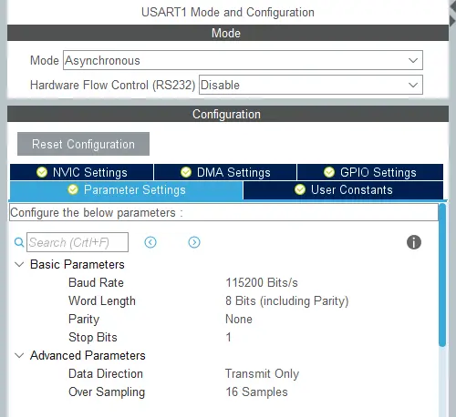
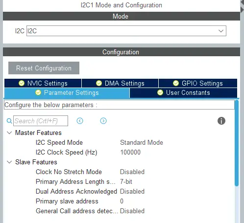
For this example project, you’ll need to configure one UART peripheral and one I2C interface in master mode. The UART will be used to send the address readings to the PC (with USB-TTL), and the I2C master will do the address scanning as we’ll see next.
I2C Scanner Project Configurations
Those are the CubeMX configurations I’ve used for UART1 & I2C1 peripherals
 |
 |
I2C Scanner Project Code Listing
|
1 2 3 4 5 6 7 8 9 10 11 12 13 14 15 16 17 18 19 20 21 22 23 24 25 26 27 28 29 30 31 32 33 34 35 36 37 38 39 40 41 42 43 44 45 46 47 48 49 50 51 52 53 54 55 56 57 58 59 60 61 |
/* * File: I2C_Scanner * Created on: Mar 28, 2020 * Ver: 1.0 * Author: Khaled Magdy * ------------------------------------------- * For More Information, Tutorials, etc. * Visit Website: www.DeepBlueMbedded.com * */ #include "main.h" #include "stdio.h" I2C_HandleTypeDef hi2c1; UART_HandleTypeDef huart1; uint8_t Buffer[25] = {0}; uint8_t Space[] = " - "; uint8_t StartMSG[] = "Starting I2C Scanning: \r\n"; uint8_t EndMSG[] = "Done! \r\n\r\n"; void SystemClock_Config(void); static void MX_GPIO_Init(void); static void MX_I2C1_Init(void); static void MX_USART1_UART_Init(void); int main(void) { uint8_t i = 0, ret; HAL_Init(); SystemClock_Config(); MX_GPIO_Init(); MX_I2C1_Init(); MX_USART1_UART_Init(); HAL_Delay(1000); /*-[ I2C Bus Scanning ]-*/ HAL_UART_Transmit(&huart1, StartMSG, sizeof(StartMSG), 10000); for(i=1; i<128; i++) { ret = HAL_I2C_IsDeviceReady(&hi2c1, (uint16_t)(i<<1), 3, 5); if (ret != HAL_OK) /* No ACK Received At That Address */ { HAL_UART_Transmit(&huart1, Space, sizeof(Space), 10000); } else if(ret == HAL_OK) { sprintf(Buffer, "0x%X", i); HAL_UART_Transmit(&huart1, Buffer, sizeof(Buffer), 10000); } } HAL_UART_Transmit(&huart1, EndMSG, sizeof(EndMSG), 10000); /*--[ Scanning Done ]--*/ while (1) { } } |
Download STM32 I2C Scanner Project Folder
Test #1 Setup & Results
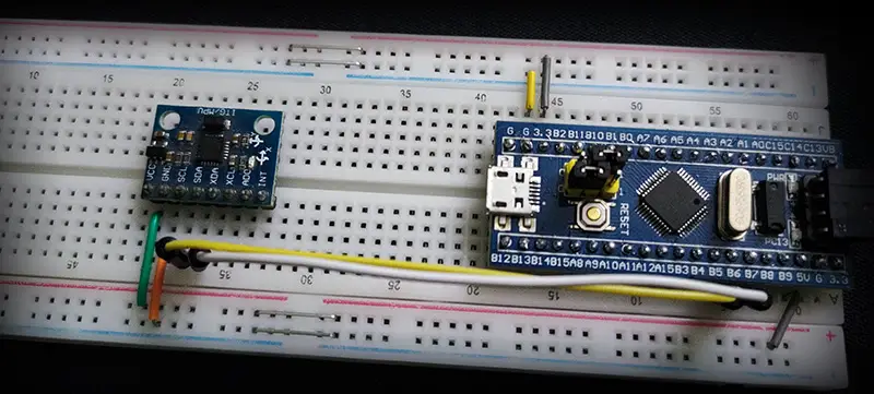
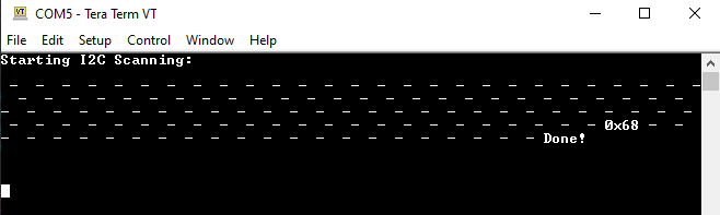
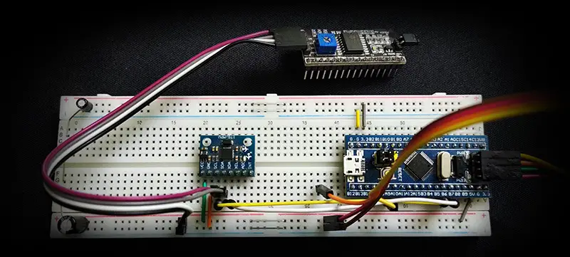
For the first test, I’ve connected an MPU6050 IMU sensor to the SCL & SDA lines of I2C1 as you can see in the image down below. The I2C address for this slave device is 0x68 as stated in the datasheet. We can change only one bit of that address so there could be 2 MPU6050 sensors on the same bus at maximum. Anyway, we should expect to see that address after running the example on the “Tera Term” serial terminal on my PC.
This is the result
Test #2 Setup & Results
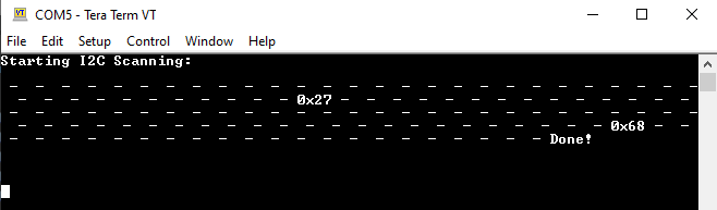
In the second test, I’ve just added another I2C module to the bus lines which is the I2C_LCD interface IO expander (PCF8574T). This module has an I2C slave address of 0x27 as a default address if no solder bridge is touched! You can still play around with those bridges to change the device address to allow many I2C_LCD devices on the same bus. Which we’ll be doing in the future in another tutorial.
But anyway, we should now expect to see another device at the 0x27 address as well as the MPU6050 at 0x68. And this is what happened exactly as you can see on the terminal screen.
Did you find this helpful? If yes, please consider supporting this work and sharing these tutorials!
Stay tuned for the upcoming tutorials and don’t forget to SHARE these tutorials. And consider SUPPORTING this work to keep publishing free content just like this!
| STM32 Course Home Page ???? |
|||||||
| Previous Tutorial | Tutorial 45 | Next Tutorial | |||||