| Previous Tutorial | Tutorial 40 | Next Tutorial | |||||
| STM32 HC-05 Bluetooth Module Interfacing + Examples | |||||||
| STM32 Course Home Page ???? | |||||||
In this tutorial, we’ll be interfacing STM32 with the HC-05 Bluetooth Module. We’ll program STM32 microcontrollers to interface HC-05 Bluetooth module in master and slave modes with pairing, test the different AT Commands for HC-05, and do some practical LAB project examples.
Unlike the previous tutorials in this series, this tutorial doesn’t include the ECUAL driver library for HC-05. However, we’ll set everything up and do various tests and LABs with HAL APIs. And we’ll set the goals and guidelines for the HC-05 Bluetooth Module library to be designed in the future and I’ll publish an article for it showing the APIs and how to use them in your application layer as you should’ve used to in this series of tutorials.
In this tutorial: 3 LABs
| LAB 52 | STM32 HC-05 Bluetooth Receiver & Smartphone Communication | ||||||
| LAB 53 | STM32 HC-05 Bluetooth Receiver & PC Communication | ||||||
| LAB 54 | STM32 How To Configure And Pair Two HC-05 Bluetooth Modules as Master & Slave MCU-To-MCU Communication Over Bluetooth | ||||||
[toc]
Required Components For LABs
All the example code/LABs/projects in the course are going to be done using those boards below.
- Nucleo32-L432KC (ARM Cortex-M4 @ 80MHz) or (eBay)
- Blue Pill STM32-F103 (ARM Cortex-M3 @ 72MHz) or (eBay)
- ST-Link v2 Debugger or (eBay)
| QTY | Component Name | ???? Amazon.com | ???? eBay.com |
| 2 | BreadBoard | Amazon | eBay |
| 1 | LEDs Kit | Amazon Amazon | eBay |
| 1 | Resistors Kit | Amazon Amazon | eBay |
| 1 | Capacitors Kit | Amazon Amazon | eBay & eBay |
| 2 | Jumper Wires Pack | Amazon Amazon | eBay & eBay |
| 1 | 9v Battery or DC Power Supply | Amazon Amazon Amazon | eBay |
| 1 | Micro USB Cable | Amazon | eBay |
| 2 | Push Buttons | Amazon Amazon | eBay |
| 1 | Micro Servo Motor (Metal Gear) | Amazon | eBay |
| 1 | Potentiometers | Amazon Amazon | eBay |
| 2 | HC-05 Bluetooth Module | Amazon | eBay |
| 1 | USB-TTL Converter or FTDI Chip | Amazon Amazon | eBay eBay |
★ Check The Full Course Complete Kit List
Some Extremely Useful Test Equipment For Troubleshooting:
- My Digital Storage Oscilloscope (DSO): Siglent SDS1104 (on Amazon.com) (on eBay)
- FeelTech DDS Function Generator: KKMoon FY6900 (on Amazon.com) (on eBay)
- Logic Analyzer (on Amazon.com) (on eBay)
Affiliate Disclosure: When you click on links in this section and make a purchase, this can result in this site earning a commission. Affiliate programs and affiliations include, but are not limited to, the eBay Partner Network (EPN) and Amazon.com.
HC-05 Bluetooth Module
HC-05 Bluetooth Module Description
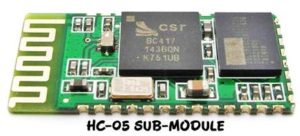
This module is based on the Cambridge Silicon Radio BC417 2.4 GHz BlueTooth Radio chip. This is a complex chip in fact which uses an external 8 Mbit flash memory. You can find more information in the associated datasheet. However, it’s fairly easy to set up and interface to any microcomputer system over the serial UART. HC-05 can be set to be either a Master or a Slave. These small modules run on 3.3V power with 3.3V serial signal levels, They are usually soldered to a larger breakout board.
Breakout Boards make these modules easy to use. HC-05 sub-modules are soldered on breakout boards to provide easier connectivity for users. Most of these boards support operation at 5V power and interface to 5V microcontroller signal levels with some techniques of level shifting. A typical “breakout” board is shown down below.
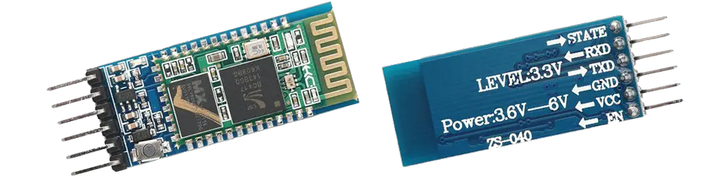
HC-05 Bluetooth Module Pinout
| Pin | Name | Functionality |
| 1 | Enable/Key | This pin is used to switch between the Data Mode (set low) and AT Command Mode (set high) Before powering-up the module. By default, it’s in Data mode. |
| 2 | Vcc | Powers-up the module. Is connected to +5V Supply voltage |
| 3 | Ground | Ground pin of the module. Is connected to your system’s ground. |
| 4 | TX | Transmits Serial Data. Everything received via Bluetooth will be given out by this pin as serial data to your microcontroller UART receiver. |
| 5 | RX | Receive Serial Data. Every serial data given to this pin will be sent via Bluetooth. |
| 6 | State | The state pin is connected to an onboard LED, it can be used as feedback to check if the Bluetooth is working properly. |
The Purpose Of The On-Board LED & Button is indicated as follows:
1- The On-Board LED
The way in which this LED is blinking indicates the status of the Module as shown below
- Blink once in 2 sec: Module has entered Command Mode
- Repeated Blinking: Waiting for connection in Data Mode
- Blink twice in 1 sec: Connection successful in Data Mode
2- The On-Board Button
It’s used to control the Enable/Key pin to switch between the Data and Command Mode.
HC-05 Bluetooth Module Technical Specs
Here are some of the technical features for the HC-05 Bluetooth modules:
- Operating Voltage: 3.3V to 6V ( Typically +5V )
- Operating Current: 30mA
- Range: ~ 9m ( 30ft )
- Works with Serial communication (USART) and TTL compatible
- Can operate in Master, Slave, or Master/Slave mode
- Can be easily interfaced with PCs or Smartphones with a Bluetooth capability
- Supported baud rate: 9600, 19200, 38400, 57600, 115200, 230400, 460800
HC-05 Bluetooth Module Default Settings
The typical default factory settings for a new Bluetooth HC-05 module are listed down below.
- Default Bluetooth Name: “HC-05”
- Default Password: 1234 or 0000
- Default Communication: Slave Device
- Default Mode: Data Mode
- Default Data Mode Baud Rate: 9600, 8, N, 1
- Default Command Mode Baud Rate: 38400, 8, N, 1
The HC-05 Bluetooth Module has two different modes of operation:
- Data Mode
- AT Command Mode
The default mode is the Data Mode with the following default settings for communication.
- Device Name: HC-05
- Password: 1234 or 0000
- Baud Rate: 9600 bps, Data: 8 bits, Stop Bits: 1 bit, Parity: None, Handshake: None
Data Mode
In Data Mode, the HC-05 Bluetooth module can be configured to operate in one of the following modes [ Master – Slave ]. Where it can transmit or receive data to/from another Bluetooth module/device.
AT Command Mode
In many situations, you may need to change some of the default configurations or their values. That’s what we use the Command Mode for. There are a couple of ways to get into Command Mode:
1- Connect the KEY pin high before applying power to the module. This will set the module into command mode at 38400 baud. This is the default baud rate for the command mode and needed if you don’t know the baud rate the module is set to. You can use a serial monitor to get the job done.
2- Apply power to the module then pull the KEY pin high. This will enter command mode at the currently configured baud rate. This is useful if you want to send AT commands from a microcontroller as the KEY pin can be controlled using one of the microcontroller’s pins. BUT you need to know the currently configured Baud Rate for the AT command mode.
Commands are sent to the module in UPPERCASE and are terminated with a CR/LF pair.
The format of commands is:
Always starts with “AT”
Then “+” followed by
Then either:
- ? (returns the current value of the parameter)
- = (Set new value for the parameter)
Few Examples:
AT (AT Test command. Should respond with OK)
AT+VERSION? (show the firmware version)
AT+UART=9600,0,0 (Set baud rate to 9600, 1 stop bit, no parity)
| Check out this previous tutorial about the same HC-05 Bluetooth Module. It might have some other useful examples as well | 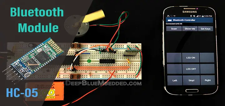 |
|
Refer To The Datasheet For More Info About This Module.
STM32 HC-05 Bluetooth Module Interfacing
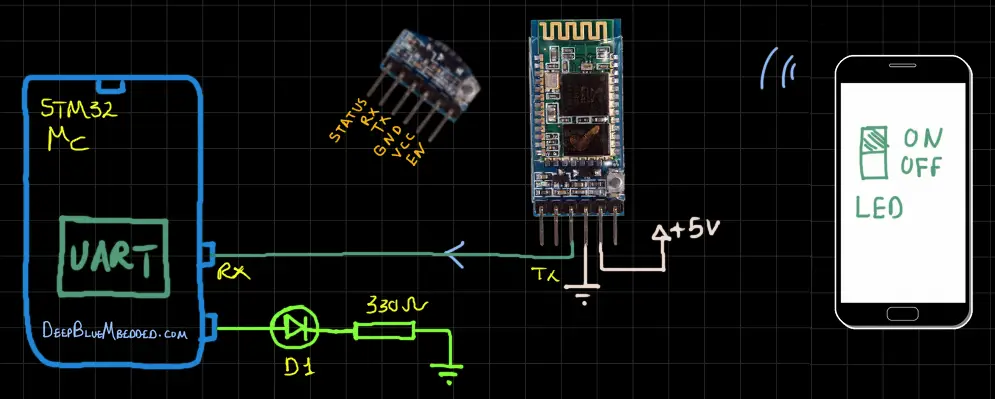
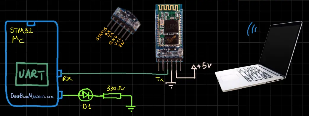
STM32 & HC-05 Bluetooth Module Connection Diagram
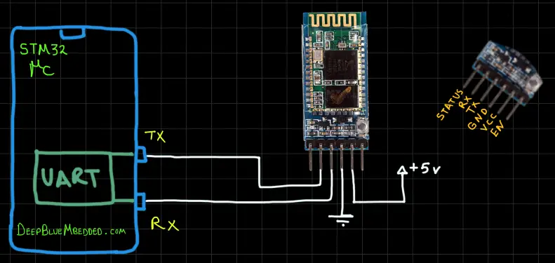
Note that both the HC-05 Bluetooth module and our STM32 microcontroller are 3.3v TTL levels. No extra voltage divider resistors are needed or anything else.
Guidelines For Designing Our HC-05 Bluetooth Driver (Library)
Here are some guidelines and requirements that we need to consider before designing the HC05 driver library. It can be improved in the future but for the beginning, it should be in line with the following:
- Has Configurable UARTx For Communicating With The HC-05 Module
- Has Configurable Operating Mode ( Master or Slave )
- Support Both AT Commands & Data Modes
- Has interrupt-based notification system when a message is completely received to the buffer or sent out
- Has a dedicated GPIO pin to power ON/OFF the HC-05 Bluetooth Module using a small BJT Transistor. And another pin to control the state of the EN pin. Those 2 pins are required by the library to be capable of “programmatically” setting the mode of the HC-05 to be Master or Slave. Or maybe change any of its internal configurations like (name, password, COM speed, etc)
This library has been added to my future project work. When it’s been implemented, I’ll publish another article showing the functionalities available, APIs with test examples, and so on. For now, we’ll write some bare test code based on HAL APIs to interface with the HC-05 Bluetooth modules.
STM32 HC-05 AT Commands Setup Configuration
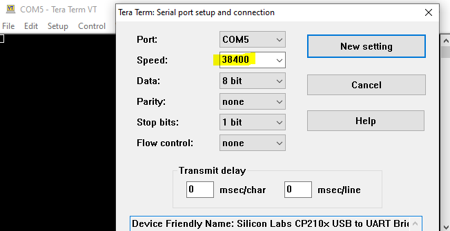
For this setup, you’d need a USB-TTL converter module with the HC-05 Bluetooth module being configured and any serial terminal software. You can also use Arduino IDE’s serial monitor but here I’ll be using Tera Term. Just connect the two modules together as shown down below and you’re good to go with the AT Commands configuration.
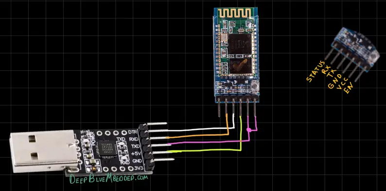
Now after wiring up everything as shown, we can proceed and plug the USB module into the PC’s port and open the serial terminal software (Tera Term in my case). And do the following configurations:
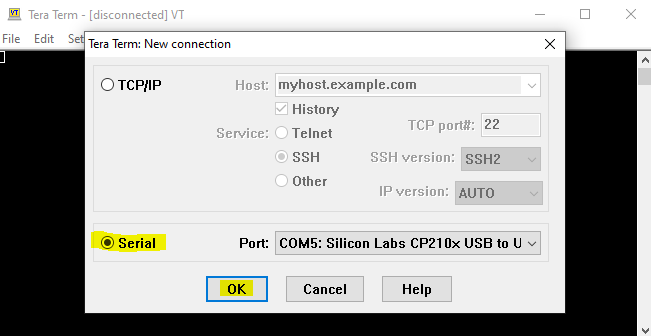
Open a new serial COM port (for the USB-TTL module as shown in your windows device manager)
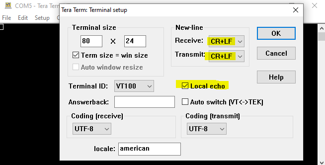
Go to Setup > Terminal and choose the following parameters
Go to Setup > Serial Port and choose 38400 Baud rate
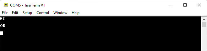
HC-05 AT Command Check
Type in “AT” and hit the enter key to send this command to the HC-05 module. If everything is working correctly, it should respond back with an “OK” message.
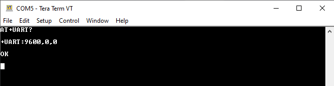
HC-05 UART Check
The default UART settings for HC-05 Bluetooth modules are (9600 baud rate, 0 stop bits, 0 parity). You can check this information by typing in “AT+UART?”. It’ll respond back with the current UART settings.
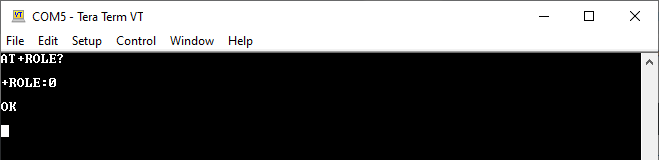
HC-05 Role (Mode) Check
The default role (mode) for HC-05 Bluetooth modules is “0” which is “Slave” mode. You can check this information by typing in “AT+ROLE?”. It’ll respond back with the current mode of operation.
HC-05 Role (Mode) Change To Master
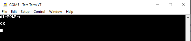
To change the role (mode) of any HC-05 Bluetooth device to be a master, type in “AT+ROLE=1”.
HC-05 Role (Mode) Change To Slave
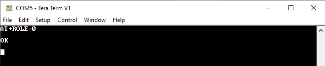
To change the role (mode) of any HC-05 Bluetooth device to be a slave, type in “AT+ROLE=0”.
HC-05 Name Check
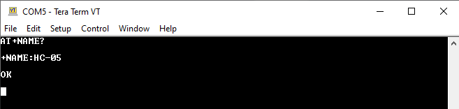
The default name for HC-05 Bluetooth modules is “HC-05”. You can check this information by typing in “AT+NAME?”. It’ll respond back with the current name for the module.
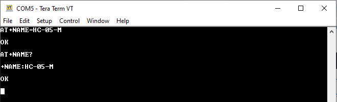
HC-05 Name Change
To change the name of any HC-05 Bluetooth device, type in “AT+NAME=YOUR_NEW_NAME”. I’ll rename the master device to be “HC-05-M” and the slave device to be “HC-05-S”.
HC-05 Password Check
The default password (PIN Code) for pairing with HC-05 Bluetooth modules is “1234”. You can check this information by typing in “AT+PSWD?”. It’ll respond back with the current password value.
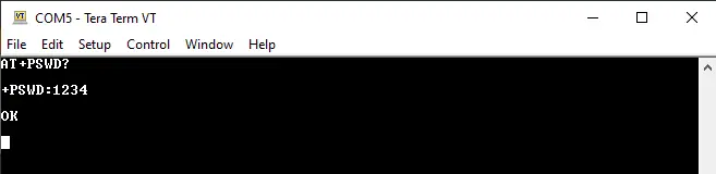
HC-05 Password Change
I won’t be changing the default password for both of my modules. But if you want to, just type in “AT+PSWD=YOU_NEW_PASSWORD” and hit enter. Then you can check if it’s been updated by typing in “AT+PSWD?”.
STM32 HC-05 Bluetooth Receiver & Smartphone – LAB
| LAB Number | 52 |
| LAB Title | STM32 HC-05 Bluetooth Receiver & Smartphone Communication |
- Set up a new project as usual with a system clock @ 72MHz (STM32F103C8T6) or whatever your uC board supports
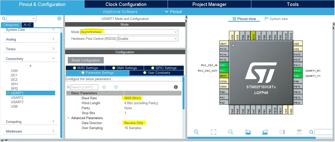
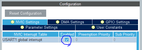
- Enable Any USART Module in Async receiver mode @ 9600bps with interrupts enabled
- Enable Any GPIO pin to be output pin for the LED control
- Initialize the peripherals used in the main application, start UART data reception in interrupt mode, whenever data is received, check its value and decide whether to turn the LED ON or OFF. Repeat!
And now, let’s build this system step-by-step
Step1: Open CubeMX & Create New Project
Step2: Choose The Target MCU & Double-Click Its Name
STM32F103C8T6 (the one I’ll be using) or any other STM32 part you’ve got
Step3: Go To The RCC Clock Configuration
Step4: Set The System Clock To Be 80MHz or whatever your uC board supports
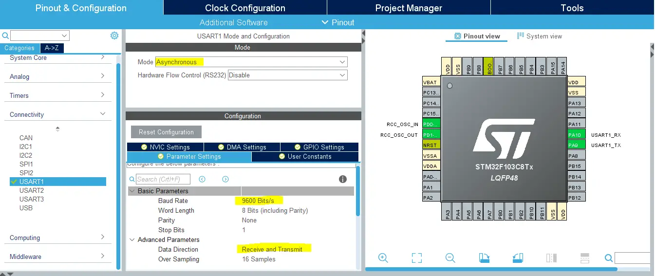
Step5: Enable Any UART Module (Async Receiver Mode) @ 9600bps + Interrupts Enabled
Step6: Enable Any GPIO Output Pin For The LED
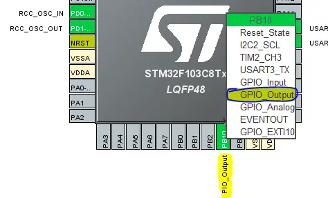
Step7: Generate The Initialization Code & Open The Project In Your IDE
Now, we can start developing our application in the main.c source file.
Here is The Application Code For This LAB (main.c)
|
1 2 3 4 5 6 7 8 9 10 11 12 13 14 15 16 17 18 19 20 21 22 23 24 25 26 27 28 29 30 31 32 33 34 35 36 37 38 39 40 |
#include "main.h" #define BUFFER_LEN 1 UART_HandleTypeDef huart1; uint8_t RX_BUFFER[BUFFER_LEN] = {0}; void SystemClock_Config(void); static void MX_GPIO_Init(void); static void MX_USART1_UART_Init(void); int main(void) { HAL_Init(); SystemClock_Config(); MX_GPIO_Init(); MX_USART1_UART_Init(); HAL_UART_Receive_IT(&huart1, RX_BUFFER, BUFFER_LEN); while (1) { if(RX_BUFFER[0] == '1') { HAL_GPIO_WritePin(GPIOB, GPIO_PIN_10, 1); } else if(RX_BUFFER[0] == '0') { HAL_GPIO_WritePin(GPIOB, GPIO_PIN_10, 0); } } } void HAL_UART_RxCpltCallback(UART_HandleTypeDef *huart) { if(huart->Instance == huart1.Instance) { HAL_UART_Receive_IT(&huart1, RX_BUFFER, BUFFER_LEN); } } |
Download The STM32 HC-05 Bluetooth Module Slave + Smartphone / PC – LAB52/53
The Result For This LAB Testing (Video)
STM32 HC-05 Bluetooth Receiver & PC Communication – LAB
| LAB Number | 53 |
| LAB Title | STM32 HC-05 Bluetooth Receiver & PC Laptop Communication |
- Set up a new project as usual with a system clock @ 72MHz (STM32F103C8T6) or whatever your uC board supports
- Enable Any USART Module in Async receiver mode @ 9600bps with interrupts enabled
- Enable Any GPIO pin to be output pin for the LED control
- Initialize the peripherals used in the main application, start UART data reception in interrupt mode, whenever data is received, check its value and decide whether to turn the LED ON or OFF. Repeat!
Exactly the same as the previous LAB. Just keep the uC as it is and head over to the PC in order to connect with the HC-05 Bluetooth module and send control data from PC->HC05 over Bluetooth.
The only difference is the Bluetooth master device. Instead of a smartphone, we’ll be using a PC with a Bluetooth host device (a Typical laptop will have it built-in by default).
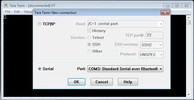
For this purpose, we’ll use Tera Term as a Bluetooth terminal. Using this application, we can search for the HC-05, pair with it, and start communication over the terminal window. open the Tera Term.exe file and select the serial COM port (Standard Serial Over Bluetooth). If the new connection window didn’t pop-up in your face, then click the File > New Connection.
Now, you should search for the HC-05 Bluetooth module and pair with it before you’re able to communicate with the module over Bluetooth. Well, now we’re good to go. Type in the terminal window “1” to turn the LED ON and “0” to turn it OFF.
STM32 How To Configure And Pair Two HC-05 Bluetooth Modules as Master And Slave (MCU-To-MCU Over Bluetooth) – LAB
| LAB Number | 54 |
| LAB Title | STM32 How To Configure And Pair Two HC-05 Bluetooth Modules as Master & Slave MCU-To-MCU Communication Over Bluetooth |
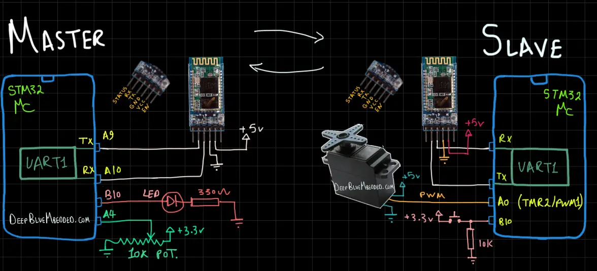
In this LAB project, we’ll configure Two HC-05 Bluetooth Modules as (Master & Slave). Get the slave Bluetooth device address and set the master to automatically pair with that device address on power-up. Then, we’ll develop a simple application to read an analog potentiometer with ADC and send that to the slave device to control a Servo motor. Using the previously develop SERVO motor driver library (refer to this linked tutorial).
The slave device will also send back a piece of info for the master device which is the state of a push button which in turn will control an LED at the master device application. It’s a very simple 2-way communication between two HC-05 Bluetooth modules just to get you started.
First of all, we need to recall the USB-TTL configuration setup that we’ll be using to configure the two HC-05 Bluetooth modules before starting to develop the 2 firmware projects (Master & Slave). Here is the setup we’ll be using for configuration:
HC-05 Bluetooth Slave Configurations
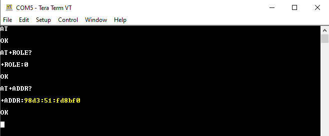
Here I’m checking the connection by “AT” which results in an “OK” message. Then, I’ll check the role of this module to make sure it’s the slave device by “AT+ROLE?” and it’s “0” which means it’s the slave module. Then, I’ll check the address value for that device by “AT+ADDR?” and I’ll save the response as we’ll need to use it for the master configuration in the next step.
HC-05 Bluetooth Master Configurations
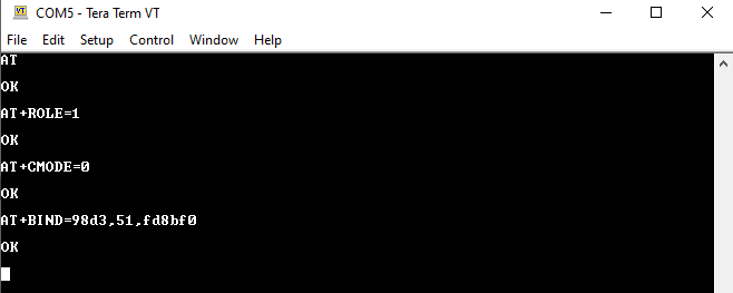
Then, I’ll configure the master HC-05 Bluetooth module. First of all, let’s check the communication by typing in the “AT” command and it does respond with an “OK”. Then, I’ll set the mode to be master mode by typing in “AT+ROLE=1”. Then, I’ll use the “AT+CMODE=0” command to set the connect mode to “Fixed Address”. And finally, by using the “AT+BIND=SLAVE_DEVICE_ADDRESS” command we will set the address of the slave device that we’ve previously saved.
STM32 HC-05 Bluetooth Master Firmware Project
Step1: Open CubeMX & Create New Project
Step2: Choose The Target MCU & Double-Click Its Name
STM32F103C8T6 (the one I’ll be using) or any other STM32 part you’ve got
Step3: Go To The RCC Clock Configuration
Step4: Set The System Clock To Be 80MHz or whatever your uC board supports
Step5: Enable Any UART Module (Async Receiver Mode) @ 9600bps + Interrupts Enabled
Step6: Enable Any GPIO Output Pin For The LED
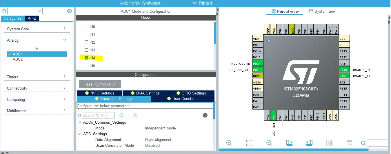
Step6: Enable Any ADC Channel For The Potentiometer
Step8: Generate The Initialization Code & Open The Project In Your IDE
Now, we can start developing our application in the main.c source file.
Here is The Application Code For The Master STM32 Device (main.c)
|
1 2 3 4 5 6 7 8 9 10 11 12 13 14 15 16 17 18 19 20 21 22 23 24 25 26 27 28 29 30 31 32 33 34 35 36 37 38 39 40 41 42 43 44 45 46 47 48 49 50 51 52 53 54 55 |
#include "main.h" #define BUFFER_LEN 1 ADC_HandleTypeDef hadc1; UART_HandleTypeDef huart1; uint8_t RX_BUFFER[BUFFER_LEN] = {0}; uint8_t TX_BUFFER[BUFFER_LEN] = {0}; void SystemClock_Config(void); static void MX_GPIO_Init(void); static void MX_ADC1_Init(void); static void MX_USART1_UART_Init(void); int main(void) { uint16_t AD_RES = 0; HAL_Init(); SystemClock_Config(); MX_GPIO_Init(); MX_ADC1_Init(); MX_USART1_UART_Init(); HAL_UART_Receive_IT(&huart1, RX_BUFFER, BUFFER_LEN); while (1) { // Start ADC Conversion HAL_ADC_Start(&hadc1); // Poll ADC1 Perihperal & TimeOut = 1mSec HAL_ADC_PollForConversion(&hadc1, 1); // Read The ADC Conversion Result & Map It To PWM DutyCycle AD_RES = HAL_ADC_GetValue(&hadc1); TX_BUFFER[0] = AD_RES>>4; HAL_UART_Transmit(&huart1, TX_BUFFER, sizeof(TX_BUFFER), 100); HAL_Delay(25); } } void HAL_UART_RxCpltCallback(UART_HandleTypeDef *huart) { if(huart->Instance == huart1.Instance) { if(RX_BUFFER[0] == '1') { HAL_GPIO_WritePin(GPIOB, GPIO_PIN_10, 1); } else if(RX_BUFFER[0] == '0') { HAL_GPIO_WritePin(GPIOB, GPIO_PIN_10, 0); } HAL_UART_Receive_IT(&huart1, RX_BUFFER, BUFFER_LEN); } } |
Download The STM32 HC-05 Bluetooth Master Project – LAB54
STM32 HC-05 Bluetooth Slave Firmware Project
Step1: Open CubeMX & Create New Project
Step2: Choose The Target MCU & Double-Click Its Name
STM32F103C8 (the one I’ll be using) or any other STM32 part you’ve got
Step3: Go To The RCC Clock Configuration
Step4: Set The System Clock To Be 72MHz or whatever your uC board supports
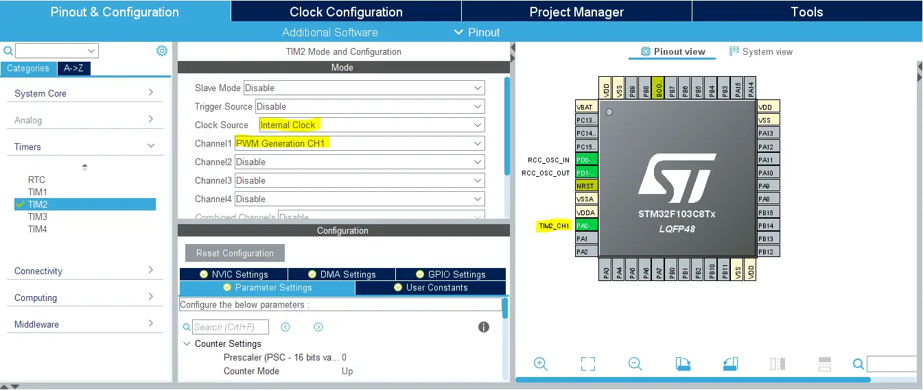
Step5: Enable Any Timer Module or The one You’ll be using For Servo Motors
We’ll have to do this step just to have the TIMER_HAL files added to our project by CubeMX. However, we’ll delete that Timer2_Init function and won’t care about TIMER PWM operation. Since the Servo library will handle that. But you’ll just have to enable any Timer Module in CubeMX in order to have the TIMER_HAL files added to your project. As the Servo library depends on them.
Step6: Enable Any GPIO Output Pin For The LED
Step7: Generate The Initialization Code & Open The Project In Your IDE
Step8: Add the ECUAL/ SERVO driver files to your project
Follow This Tutorial which shows you How To Add Any ECUAL Driver To An STM32 Project step-by-step.

You basically right-click the project name in the IDE’s navigator and choose to create a new > source folder. And name it ECUAL and go to the GitHub repo, download the files and copy the “SERVO” folder and back to the IDE, right-click on the ECUAL and paste the library into it.
Step9: Add the MATH files & util
You basically right-click the project name in the IDE’s navigator and choose to create a new > source folder. And name it util and go to the GitHub repo, download the files and copy the files inside the “util” folder and back to the IDE, right-click on the util and paste them into that folder. The same goes for the MATH folder as well.
Now, we can start developing our application in the main.c source file.
Here is The Application Code For The Slave STM32 Device (main.c)
|
1 2 3 4 5 6 7 8 9 10 11 12 13 14 15 16 17 18 19 20 21 22 23 24 25 26 27 28 29 30 31 32 33 34 35 36 37 38 39 40 41 42 43 44 45 46 47 48 49 50 51 52 53 54 55 |
#include "main.h" #include "../MATH/MATH.h" #include "../ECUAL/SERVO/SERVO.h" #define BUFFER_LEN 1 #define ServoMotor1 0 UART_HandleTypeDef huart1; uint8_t RX_BUFFER[BUFFER_LEN] = {0}; uint8_t TX_BUFFER[BUFFER_LEN] = {0}; void SystemClock_Config(void); static void MX_GPIO_Init(void); static void MX_USART1_UART_Init(void); int main(void) { uint16_t Servo1Pulse = 0; uint16_t Servo1MaxPulse = 0, Servo1MinPulse = 0; HAL_Init(); SystemClock_Config(); MX_GPIO_Init(); MX_USART1_UART_Init(); SERVO_Init(ServoMotor1); HAL_UART_Receive_IT(&huart1, RX_BUFFER, BUFFER_LEN); Servo1MinPulse = SERVO_Get_MinPulse(ServoMotor1); Servo1MaxPulse = SERVO_Get_MaxPulse(ServoMotor1); while (1) { if(HAL_GPIO_ReadPin(GPIOB, GPIO_PIN_10)) { TX_BUFFER[0] = '1'; } else { TX_BUFFER[0] = '0'; } HAL_UART_Transmit(&huart1, TX_BUFFER, 1, 10); Servo1Pulse = MAP(RX_BUFFER[0], 0, 255, Servo1MinPulse, Servo1MaxPulse); SERVO_RawMove(ServoMotor1, Servo1Pulse); HAL_Delay(10); } } void HAL_UART_RxCpltCallback(UART_HandleTypeDef *huart) { if(huart->Instance == huart1.Instance) { HAL_UART_Receive_IT(&huart1, RX_BUFFER, BUFFER_LEN); } } |
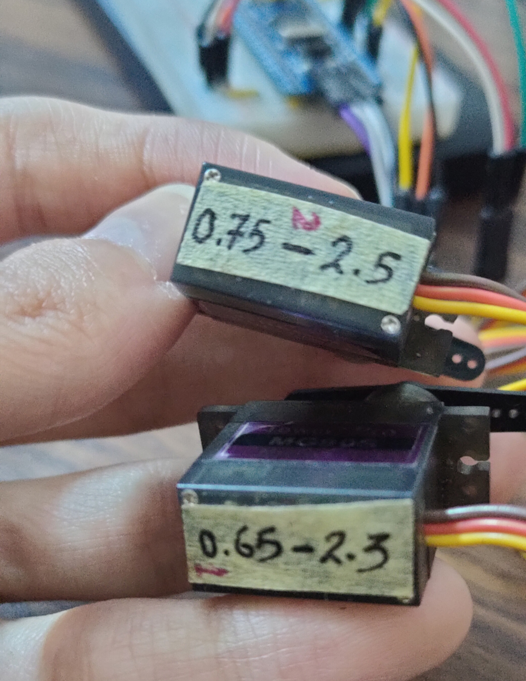
Note: The TIM2_Init function has been removed because Servo_Init will handle this. And I did firstly read the min & max pulse count for my servo motor just to define the full range of motion for it. This will step is required to make the mapping process as accurate as possible. You can refer to my old article about servo motors to know more about the min & max pulse and how I did come up with these values. As you’ll notice in SERVO_cfg.c file, the defined min & max pulse widths are slightly different for different motors.
Download The STM32 HC-05 Bluetooth Slave Project – LAB54
The Result For This LAB Testing (Video)
Did you find this helpful? If yes, please consider supporting this work and sharing these tutorials!
Stay tuned for the upcoming tutorials and don’t forget to SHARE these tutorials. And consider SUPPORTING this work to keep publishing free content just like this!
| Previous Tutorial | Tutorial 40 | Next Tutorial | |||||