| Previous Tutorial | Tutorial 34 | Next Tutorial | |||||
| STM32 GPIO – (LEDs / Buttons) Driver | |||||||
| STM32 Course Home Page ???? | |||||||

Back again to resume those STM32 tutorials. In this tutorial, we’ll be discussing the usage of STM32 GPIO pins to drive LEDs and read the digital state of push buttons (switches). As well as addressing the bouncing issue and how to debounce switches using a simple form of digital filtering just to avoid “delay insertion” and have a kind of “RTOS friendly” driver code for reading the Buttons.
We’ll be discussing how and why I’ve built those two ECUAL drivers for LEDs & Buttons, do some tests and measurements and give you some step by step LAB examples to test out, and also to help you add those drivers to your embedded applications with any STM32 microcontroller you choose. Without further ado, let’s get right into it!
[toc]
Required Components For LABs
All the example code/LABs/projects in the course are going to be done using those boards below.
- Nucleo32-L432KC (ARM Cortex-M4 @ 80MHz) or (eBay)
- Blue Pill STM32-F103 (ARM Cortex-M3 @ 72MHz) or (eBay)
- ST-Link v2 Debugger or (eBay)
| QTY | Component Name | ???? Amazon.com | ???? eBay.com |
| 2 | BreadBoard | Amazon | eBay |
| 1 | LEDs Kit | Amazon Amazon | eBay |
| 1 | Resistors Kit | Amazon Amazon | eBay |
| 1 | Capacitors Kit | Amazon Amazon | eBay & eBay |
| 2 | Jumper Wires Pack | Amazon Amazon | eBay & eBay |
| 1 | 9v Battery or DC Power Supply | Amazon Amazon Amazon | eBay |
| 1 | Micro USB Cable | Amazon | eBay |
| 1 | Push Buttons | Amazon Amazon | eBay |
★ Check The Full Course Complete Kit List
Some Extremely Useful Test Equipment For Troubleshooting:
- My Digital Storage Oscilloscope (DSO): Siglent SDS1104 (on Amazon.com) (on eBay)
- FeelTech DDS Function Generator: KKMoon FY6900 (on Amazon.com) (on eBay)
- Logic Analyzer (on Amazon.com) (on eBay)
Affiliate Disclosure: When you click on links in this section and make a purchase, this can result in this site earning a commission. Affiliate programs and affiliations include, but are not limited to, the eBay Partner Network (EPN) and Amazon.com.
Reading & Debouncing Switches
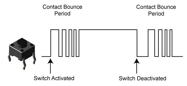
After configuring any GPIO pin to operate as a digital input pin, you can just hook up your button to that pin and read the corresponding port register value to get the digital pin state. So your uC can know the state of the push button and react correspondingly. However, it’s not recommended to react based on that raw digital state of the button as it’s usually prone to transient noise, called bouncing, which will end up showing on your output as some glitches or flickering at the edge of each state transition.
This issue arises from the mechanical nature of how push buttons actually operate. The moment of physical contact is when your GPIO pin experiences some high-frequency flip-flop kind of signal until it’s a clean HIGH or LOW (depending on your configuration pull-up or pull-down). This is what we commonly refer to as switch bouncing and there are many techniques that address this issue to provide switch debouncing solutions.
Switch debouncing techniques can be categorized into two distinct categories, the first of which is the hardware debouncing that includes adding in an RC filter or using a dedicated IC for that task and so on. The other category is software-based solutions like adding in a certain amount of delay after reading the button for the first time and wait for the state to settle down or performing some sort of counting at fixed time intervals to make sure that the button state is stable.
Or alternatively, we can use a simple digital filter like the moving average filter and that’s what we’re going to do in this tutorial. Each SysTick (1ms or multiples of it, whatever it is in your system), we’ll read in the digital state of the push button and save it to a buffer array. Let the buffer length be 4 bytes for example, now if you look at that 4-byte long buffer at any instance of time, it’s going to reflect the history of the last 4 states for that push button.
We can sum the last 4 states and if the sum equals 4, we can consider the button to be HIGH. Otherwise, it’s a LOW. This is actually a “special case” of the general FIR (finite impulse response) digital filters with all coefficients being the same and equal to (0.25 or generally 1/n, where n is the length of the buffer). This creates an LPF (low pass filter) effect on the output of the system which is what we want indeed, just to get rid of the high-frequency bouncing artifacts.

Have a look at this diagram below and keep track of the state for the following things: [ the physical pin state – the history buffer summation – the output to the LED ]
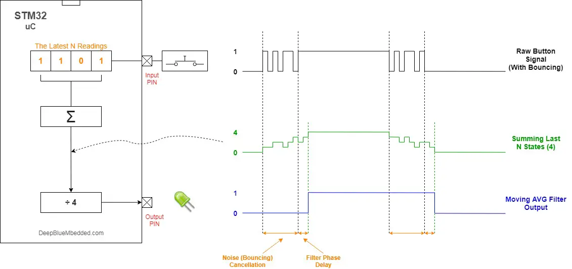
As you can see in the diagram above, the output signal is clean and we did succeed to eliminate the switch bouncing artifacts. However, as you may have also noted, the introduction of this simple LPF digital filter did also introduce a “phase delay” which is basically the time it takes our system to have the output state changed in response to the input button state change. This is totally fine and we can always compromise between faster response time and accepting a little bit of input noise while suppressing most of it. There is always something in between.
STM32 Buttons ECUAL Driver
The ECUAL Buttons driver is built for STM32 microcontrollers using some GPIO pins. You’ll have to configure an instance of it and use the APIs to read your buttons and that’s all. The code should be easily ported to any other STM32 microcontroller or reconfigured to use any GPIO pins you want just as we’ll see in this section. And here is a link for the course’s repo, and you’ll find the BUTTONS driver in the ECUAL directory as usual.
Buttons Driver Code Files
The Buttons driver consists of the following files:
|
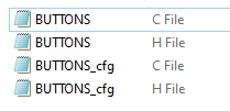 |
You’ll need only to modify the configuration files. The source code for this driver is found in (BUTTONS.c) and to use it you’ll include the header (BUTTONS.h). Nothing in the source code needs to be changed at all unless you need to add any extra features or customize the driver for your application’s needs. For today’s labs, we’ll only be changing the configuration files to build some test applications.
Therefore, I’ll write here the code listing for the BUTTONS.h & BUTTONS_cfg.c files.
BUTTONS.h File
|
1 2 3 4 5 6 7 8 9 10 11 12 13 14 15 16 17 18 19 20 21 22 23 24 25 26 27 28 29 30 31 32 33 34 35 36 37 38 39 40 41 42 43 44 45 46 47 |
#define HAL_GPIO_MODULE_ENABLED #include "stm32f1xx_hal.h" // The Number OF Button Units To Be Used In The Project #define BTN_UNITS 2 #define BTN_PRESSED 1 #define BTN_RELEASED 0 #define BTNS_FILTER_ORDER 8 typedef struct { GPIO_TypeDef * BTN_GPIO; /* * GPIOA * GPIOB * ... * */ uint16_t BTN_PIN; /* * GPIO_PIN_0 * GPIO_PIN_1 * ... * */ uint16_t PULL_MODE; /* * GPIO_NOPULL * GPIO_PULLUP * GPIO_PULLDOWN * */ uint16_t Filter_Order; /* * 0 * 1 * .. * N * */ }BTN_CfgType; /*-----[ Prototypes For All Functions ]-----*/ void BTNs_Init(uint8_t* BTN_States); void BTN_Main(void); void BTN_Read(uint16_t au16_Instance, uint8_t* BTN_State); |
If you’re willing to use many push buttons, just adjust that number definition (BTN_UNITS).
Buttons Driver APIs
As you’ve seen in the BUTTONS.h file, the provided APIs does all the basic functionalities that you may need from a buttons driver library. It initialized the required GPIO pins and read the raw state of the pin at any instance of time. And it also gives you the main scanning and filtering logic in the function BTN_Main() that you can call periodically within your SysTick ISR or in a task if you’re using an RTOS or whatever.
The structure of the files and the provided APIs look very intuitive and self-explanatory to me. And the example LABs will put everything under test and you’ll see how and when to use each of these functions.
BUTTONS_cfg.c File
|
1 2 3 4 5 6 7 8 9 10 11 12 13 14 |
#include "BUTTONS.h" const BTN_CfgType BTN_CfgParam[BTN_UNITS] = { // Button 1 Configurations { GPIOA, GPIO_PIN_6, GPIO_NOPULL, BTNS_FILTER_ORDER } }; uint8_t Filters_Buffers[BTN_UNITS][BTNS_FILTER_ORDER+1] = {0}; |
I’ll discuss those configuration parameters in the next section down below.
Available Configurations For ECUAL Buttons Driver
From the code above in BUTTONS.h & BUTTONS_cfg.c you can see that there are not many parameters in the configuration structure. The config structure will be used to assign the pin you want to the button, decide on the pull mode for this pin (up, down, no pull), and also the digital filter order for that button. The filter order can be any number [ 1 – 2 – 3 …. – N ] but it’s advised to be around 8 in case you’re using a SysTick of 1ms, or you can just tweak it as you want.
Typical Usage Application Example
Here is a typical usage application for this driver in order to initialize a push-button and read its state to drive ON or OFF an output pin.
|
1 2 3 4 5 6 7 8 9 10 11 12 13 14 15 16 17 18 19 20 21 22 23 24 25 26 27 28 29 30 31 |
#include "main.h" #include "../ECUAL/BUTTONS/BUTTONS.h" #define BTN1 0 void SystemClock_Config(void); static void MX_GPIO_Init(void); uint8_t gu8_BTN_States; int main(void) { HAL_Init(); SystemClock_Config(); MX_GPIO_Init(); BTNs_Init(&gu8_BTN_States); while (1) { /* Read Button */ BTN_Read(BTN1, &gu8_BTN_States); /* Check State & Write Output */ if(gu8_BTN_States == BTN_PRESSED) { HAL_GPIO_WritePin(GPIOB, GPIO_PIN_13, 1); } else { HAL_GPIO_WritePin(GPIOB, GPIO_PIN_13, 0); } } } |
Buttons Main Function
In the BUTTONS.c source code file, you’ll find the implementation of this function “BTN_Main()“. I highly recommend that you take the time to figure it out. This function is written in this way in order to be called asynchronously from the main application or the OS dispatcher if you have got a task for the buttons scanning. It does handle all the logical operations for reading and filtering the state for all buttons in your application, and writes out the buttons states to the buffer array that you’ve got to check in the main application.
And yes, it has to be called repeatedly at a steady rate as we’ll see in one of the LAB examples hereafter.
STM32 LEDs ECUAL Driver
The ECUAL LEDs driver is built for STM32 microcontrollers using some GPIO pins. You’ll have to configure an instance of it and use the APIs to control your LEDs and that’s all. The code should be easily ported to any other STM32 microcontroller or reconfigured to use any GPIO pins you want just as we’ll see in this section. And here is a link for the course’s repo, and you’ll find the LEDS driver in the ECUAL directory as usual.
LEDS Driver Code Files
The LEDS driver consists of the following files:
|
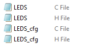 |
You’ll need only to modify the configuration files. The source code for this driver is found in (LEDS.c) and to use it you’ll include the header (LEDS.h). Nothing in the source code needs to be changed at all unless you need to add any extra features or customize the driver for your application’s needs. For today’s labs, we’ll only be changing the configuration files to build some test applications.
Therefore, I’ll write here the code listing for the LEDS.h & LEDS_cfg.c files.
LEDS.h File
|
1 2 3 4 5 6 7 8 9 10 11 12 13 14 15 16 17 18 19 20 21 22 23 24 25 26 27 28 |
#define HAL_GPIO_MODULE_ENABLED #include "stm32f1xx_hal.h" // The Number OF LED Units To Be Used In The Project #define LED_UNITS 2 typedef struct { GPIO_TypeDef * LED_GPIO; /* * GPIOA * GPIOB * ... * */ uint16_t LED_PIN; /* * GPIO_PIN_0 * GPIO_PIN_1 * ... * */ }LED_CfgType; /*-----[ Prototypes For All Functions ]-----*/ void LEDs_Init(void); void LED_ON(uint16_t au16_Instance); void LED_OFF(uint16_t au16_Instance); |
If you’re willing to use many LEDs, just adjust that number definition (LED_UNITS).
LEDs Driver APIs
As you’ve seen in the LEDS.h file, the provided APIs does all the basic functionalities that you may need from a LED driver library. It initialized the required GPIO pins and turn ON or OFF each individual LED by its instance number identifier.
The structure of the files and the provided APIs look very intuitive and self-explanatory to me. And the example LABs will put everything under test and you’ll see how and when to use each of these functions.
LEDS_cfg.c File
|
1 2 3 4 5 6 7 8 9 10 |
#include "LEDS.h" const LED_CfgType LED_CfgParam[LED_UNITS] = { // LED 1 Configurations { GPIOB, GPIO_PIN_12 } }; |
I’ll discuss those configuration parameters in the next section down below.
Available Configurations For ECUAL LEDs Driver
From the code above in LEDS.h & LEDS_cfg.c you can see that there are not many parameters in the configuration structure. The config structure will be used to assign the pin you want to the LED and that’s all.
You can, however, add some more controls like if this LED is going to be dimmable or not, if yes then it’s gonna be assignable to a timer channel for PWM, the output driver speed shall be a configurable parameter as well. A high-speed output driver is essential for high-sped PWM signals. And many more possibilities.
Typical Usage Application Example
Here is a typical usage application for this driver in order to blink an LED.
|
1 2 3 4 5 6 7 8 9 10 11 12 13 14 15 16 17 18 19 20 21 22 |
#include "main.h" #include "../ECUAL/LEDS/LEDS.h" #define LED_BLUE 0 void SystemClock_Config(void); static void MX_GPIO_Init(void); int main(void) { HAL_Init(); SystemClock_Config(); MX_GPIO_Init(); LEDs_Init(); while (1) { LED_ON(LED_BLUE); HAL_Delay(100); LED_OFF(LED_BLUE); HAL_Delay(100); } } |
Astable LED Example – LAB
| LAB Number | 32 |
| LAB Title | STM32 Astable LED Driver Test |
- Set up a new project as usual with system clock @ 72MHz or whatever your board supports
- Add the ECUAL / LEDS driver files to our project. As shown here
- configure 2 LEDs instances in LEDS_cfg.c file
- Initialize the LEDS using LEDS_Init() api, and use the LED_ON() & LED_OFF() functions to blink the LEDs within your main application in main.c file
And now, let’s build this system step-by-step
Step1: Open CubeMX & Create New Project
Step2: Choose The Target MCU & Double-Click Its Name
STM32F103C8
Step3: Go To The Clock Configuration
Step4: Set The System Clock To Be 72MHz or whatever your board supports
Step5: Generate The Initialization Code & Open The Project In Your IDE
Step6: Add the ECUAL LEDS driver files to your project
Follow This Tutorial which shows you How To Add Any ECUAL Driver To An STM32 Project step-by-step.

Here is The Application Code For This LAB (main.c)
|
1 2 3 4 5 6 7 8 9 10 11 12 13 14 15 16 17 18 19 20 21 22 23 24 25 26 |
#include "main.h" #include "../ECUAL/LEDS/LEDS.h" #define LED_BLUE 0 #define LED_YELLOW 1 void SystemClock_Config(void); static void MX_GPIO_Init(void); int main(void) { HAL_Init(); SystemClock_Config(); MX_GPIO_Init(); LEDs_Init(); while (1) { LED_ON(LED_BLUE); LED_OFF(LED_YELLOW); HAL_Delay(250); LED_OFF(LED_BLUE); LED_ON(LED_YELLOW); HAL_Delay(250); } } |
Download The STM32 Astable LED LAB32
The Result For This LAB Testing (Video)
Basic Unfiltered Button Read Example – LAB
| LAB Number | 33 |
| LAB Title | STM32 Basic Unfiltered Buttons Read |
- Set up a new project as usual with a system clock @ 72MHz or whatever your board supports
- Add the ECUAL / LEDS driver files to our project. As shown here
- Add the ECUAL / BUTTONS driver files to our project.
- Create a source folder name it MATH & Add the MATH files to our project.
- Configure 2 LEDs instances in LEDS_cfg.c file
- Configure 2 Buttons instances in BUTTONS_cfg.c file
- Initialize the LEDs & Buttons in the main application, read the buttons, turn on or off the LEDs correspondingly.
And now, let’s build this system step-by-step
Step1: Open CubeMX & Create New Project
Step2: Choose The Target MCU & Double-Click Its Name
STM32F103C8
Step3: Go To The Clock Configuration
Step4: Set The System Clock To Be 72MHz or whatever your board supports
Step5: Generate The Initialization Code & Open The Project In Your IDE
Step6: Add the ECUAL LEDS driver files to your project
Follow This Tutorial which shows you How To Add Any ECUAL Driver To An STM32 Project step-by-step.
Step7: Add the ECUAL BUTTONS driver files to your project, same as always
Step8: Add the MATH files to your project, as shown in the guide above
Here is The Application Code For This LAB (main.c)
|
1 2 3 4 5 6 7 8 9 10 11 12 13 14 15 16 17 18 19 20 21 22 23 24 25 26 27 28 29 30 31 32 33 34 35 36 37 38 39 40 41 42 43 44 45 |
#include "main.h" #include "../ECUAL/LEDS/LEDS.h" #include "../ECUAL/BUTTONS/BUTTONS.h" #define BTN1 0 #define BTN2 1 #define LED_BLUE 0 #define LED_YELLOW 1 void SystemClock_Config(void); static void MX_GPIO_Init(void); uint8_t gu8_BTN_States[BTN_UNITS]; int main(void) { HAL_Init(); SystemClock_Config(); MX_GPIO_Init(); LEDs_Init(); BTNs_Init(gu8_BTN_States); while (1) { // Read Buttons BTN_Read(BTN1, &gu8_BTN_States[BTN1]); BTN_Read(BTN2, &gu8_BTN_States[BTN2]); // Check State & Drive LEDs Output if(gu8_BTN_States[BTN1] == BTN_PRESSED) { LED_ON(LED_YELLOW); } else { LED_OFF(LED_YELLOW); } if(gu8_BTN_States[BTN2] == BTN_PRESSED) { LED_ON(LED_BLUE); } else { LED_OFF(LED_BLUE); } } } |
Download The STM32 Basic Unfiltered Buttons Reading LAB33
The Result For This LAB Testing (Video)
As you’ve seen in the demo video for this lab, the switch bouncing noise is getting coupled to our LED output signal as shown on my DSO screen. Therefore, we’ll use the button read with filtering in the next lab to test how it’s going to perform.
Debounced Button Read Example – LAB
| LAB Number | 34 |
| LAB Title | STM32 Debounced Buttons Reading |
- Set up a new project as usual with a system clock @ 72MHz or whatever your board supports
- Add the ECUAL / LEDS driver files to our project. As shown here
- Add the ECUAL / BUTTONS driver files to our project.
- Create a source folder name it MATH & Add the MATH files to our project.
- Configure 2 LEDs instances in LEDS_cfg.c file
- Configure 2 Buttons instances in BUTTONS_cfg.c file
- Initialize the LEDs & Buttons in the main application, read the buttons, turn on or off the LEDs correspondingly.
And now, let’s build this system step-by-step
Step1: Open CubeMX & Create New Project
Step2: Choose The Target MCU & Double-Click Its Name
STM32F103C8
Step3: Go To The Clock Configuration
Step4: Set The System Clock To Be 72MHz or whatever your board supports
Step5: Generate The Initialization Code & Open The Project In Your IDE
Step6: Add the ECUAL LEDS driver files to your project
Follow This Tutorial which shows you How To Add Any ECUAL Driver To An STM32 Project step-by-step.
Step7: Add the ECUAL BUTTONS driver files to your project, same as always
Step8: Add the MATH files to your project, as shown in the guide above
Now, we can start developing our application in the main.c source file.
Here is The Application Code For This LAB (main.c)
|
1 2 3 4 5 6 7 8 9 10 11 12 13 14 15 16 17 18 19 20 21 22 23 24 25 26 27 28 29 30 31 32 33 34 35 36 37 38 39 40 41 42 43 44 45 46 47 48 49 50 51 52 53 54 55 |
#include "main.h" #include "../ECUAL/LEDS/LEDS.h" #include "../ECUAL/BUTTONS/BUTTONS.h" #define BTN1 0 #define BTN2 1 #define LED_BLUE 0 #define LED_YELLOW 1 uint8_t gu8_Buttons_States[BTN_UNITS] = {0}; void SystemClock_Config(void); static void MX_GPIO_Init(void); void SysTick_CallBack(void); int main(void) { HAL_Init(); SystemClock_Config(); MX_GPIO_Init(); LEDs_Init(); BTNs_Init(gu8_Buttons_States); while (1) { // No Need To Read Button States Again Here // They're Being Read, Filtered, and Updated // In BTN_Main() Routine // Check Each Button Filtered State & React if(gu8_Buttons_States[BTN1] == BTN_PRESSED) { LED_ON(LED_YELLOW); } else { LED_OFF(LED_YELLOW); } if(gu8_Buttons_States[BTN2] == BTN_PRESSED) { LED_ON(LED_BLUE); } else { LED_OFF(LED_BLUE); } } } void SysTick_CallBack() { // Each SysTick: Call BTN_Main() BTN_Main(); } |
Note that the BTN_Main function is being called from the SysTick callback function. This function needs to be called inside the ISR handler for the SysTick timer. The HAL_Init initializes the systick timer and the HAL_Delay uses it to work as well. So, let’s open this file (stm32f1xx_it.c) and search for the SysTick handler and call our SysTick_Callback from there as shown below.
|
1 2 3 4 5 |
void SysTick_Handler(void) { HAL_IncTick(); SysTick_CallBack(); } |
Download The STM32 Debounced Buttons Reading LAB34
The Result For This LAB Testing (Video)
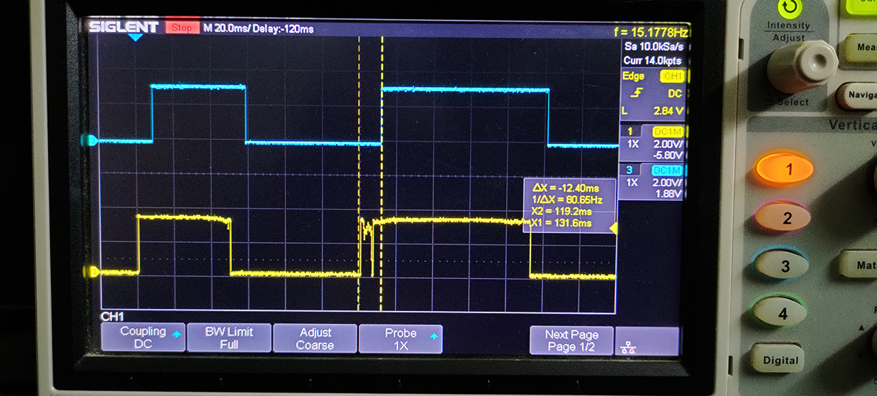
As you’ve seen in the demo video for this lab, the switch bouncing noise can no longer appear on the LED output signal as shown on my DSO screen. You can also increase the filter order in the configuration file to get an even stronger effect, however, this will amplify the phase delay in the response of our button at the end of the day.
One Last Test For Buttons Driver Code
I’ve also done one last test that I’d like to share with you. It was an approximate measurement for the execution time for the function BTN_Main. Because we’re going to build a very basic operating system in the future and also make some RTOS applications, it’s important to know the execution time of such routines like the push-buttons reading and filtering logic handler.
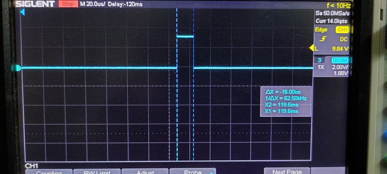
I’ve used a GPIO pin configured in fast mode push-pull driver output for fast edges switching on the output pin and driven it high before calling the BTN_Main function and bring it low when it returns. And it turned out to be 16μs which is quite good as a beginning and needs no more optimization in the meantime.
Please note that this test was done with a CPU clock of 72MHz, and the filter order was 8, and the buttons count was 2 buttons. Using a lower order filter will reduce the execution time indeed as well as increasing the processing speed. However, adding more buttons will increase the execution time quite a bit.
Did you find this helpful? If yes, please consider supporting this work and sharing these tutorials!
Stay tuned for the upcoming tutorials and don’t forget to SHARE these tutorials. And consider SUPPORTING this work to keep publishing free content just like this!
| Previous Tutorial | Tutorial 34 | Next Tutorial | |||||
One finding:
In Master file (FIR.h):
#define FILTER_DATA_TYPE float
For Lab 34 to work, set (FIR.h):
#define FILTER_DATA_TYPE uint8_t
Thanks for noting this!
The file has been updated and that’s the cause for this issue