| Previous Tutorial | Tutorial 10 | Next Tutorial | |||||
| STM32 Debugging With UART Serial Print | |||||||
| STM32 Course Home Page ???? | |||||||
In this tutorial/LAB, we’ll discuss how to debug your projects using UART serial print. As we’ve seen in an earlier tutorial that the serial wire debug (SWD) trace feature requires access to the SWO pin which is not accessible directly in the ST-Link v2 USB clone, and also not connected on the Nucleo32-L432KC board. So we weren’t able to test the SWD trace!
However, there still a couple of other methods to debug your projects, one of which is the UART serial print. And that’s what we’ll be doing in the LAB/Tutorial on both boards: Blue Pill and Nucelo32-L432KC.
[toc]
Required Components For LABs
All the example code/LABs/projects in the course are going to be done using those boards below.
- Nucleo32-L432KC (ARM Cortex-M4 @ 80MHz) or (eBay)
- Blue Pill STM32-F103 (ARM Cortex-M3 @ 72MHz) or (eBay)
- ST-Link v2 Debugger or (eBay)
| QTY | Component Name | ???? Amazon.com | ???? eBay.com |
| 2 | BreadBoard | Amazon | eBay |
| 1 | LEDs Kit | Amazon Amazon | eBay |
| 1 | Resistors Kit | Amazon Amazon | eBay |
| 1 | Capacitors Kit | Amazon Amazon | eBay & eBay |
| 2 | Jumper Wires Pack | Amazon Amazon | eBay & eBay |
| 1 | 9v Battery or DC Power Supply | Amazon Amazon Amazon | eBay |
| 1 | Micro USB Cable | Amazon | eBay |
| 1 | Push Buttons | Amazon Amazon | eBay |
| 1 | USB-TTL Converter or FTDI Chip | Amazon Amazon | eBay eBay |
★ Check The Full Course Complete Kit List
Some Extremely Useful Test Equipment For Troubleshooting:
- My Digital Storage Oscilloscope (DSO): Siglent SDS1104 (on Amazon.com) (on eBay)
- FeelTech DDS Function Generator: KKMoon FY6900 (on Amazon.com) (on eBay)
- Logic Analyzer (on Amazon.com) (on eBay)
Affiliate Disclosure: When you click on links in this section and make a purchase, this can result in this site earning a commission. Affiliate programs and affiliations include, but are not limited to, the eBay Partner Network (EPN) and Amazon.com.
STM32 Nucleo32-L432KC Serial Port
| LAB Number | 4 |
| LAB Title | Nucleo32 Serial Port Printing With UART2 |
The STM32L432KC microcontroller has 3 USART modules (USART1, USART2, and USART3). You can actually use any one of them to send serial data to your PC’s terminal using a USB-TTL converter. However, the USART2 module is connected to the onboard ST-Link programmer/debugger and it gets a virtual COM port on your PC. So there is no need to connect an external USB-TTL converter if you’re using USART2 peripheral. And that’s what we’re going to do in this section.
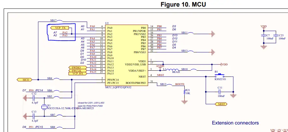
Here is the schematic diagram for the Nucleo32 board where you can see the pins PA2, PA3 (RX, TX For USART2) are connected to the onboard ST-Link MCU. I’ll have to check other Nucleo boards if this holds true for all other boards or not. And you can also double-check the schematic to make sure which USART module is being used for the virtual COM serial port communication.
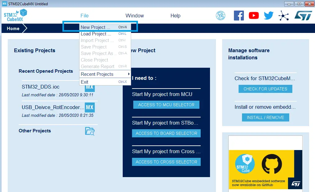
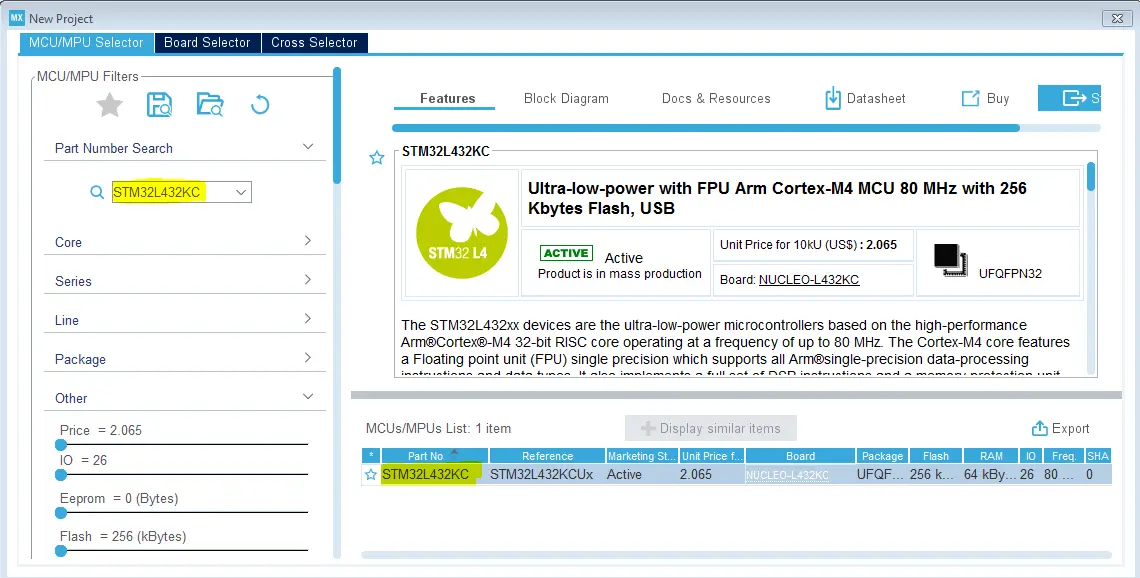
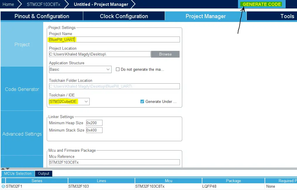
Step1: Open CubeMX & Create New Project
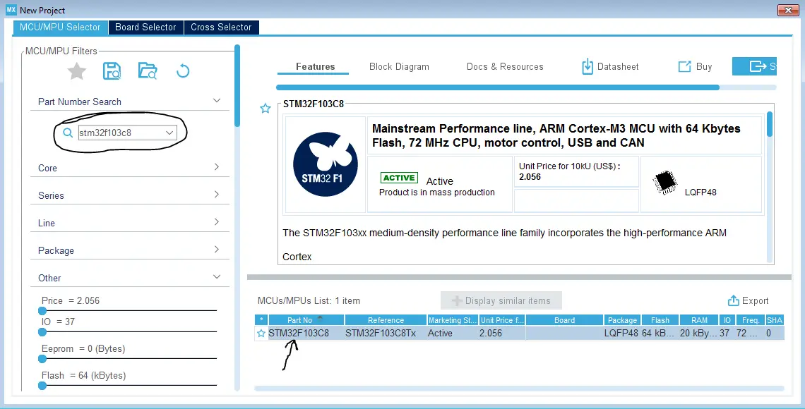
Step2: Choose The Target MCU & Double-Click Its Name
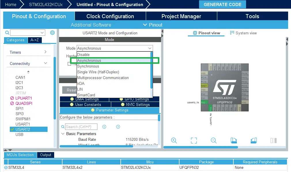
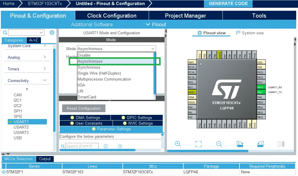
Step3: Enable USART2 Module (Asynchronous Mode)
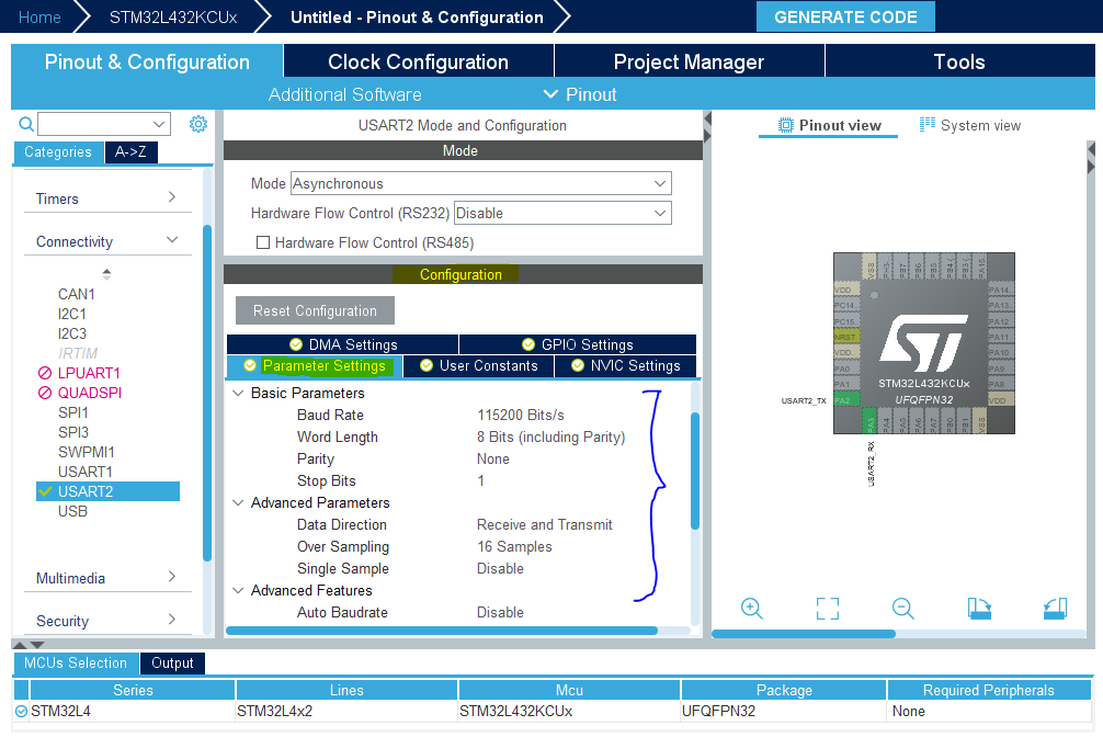
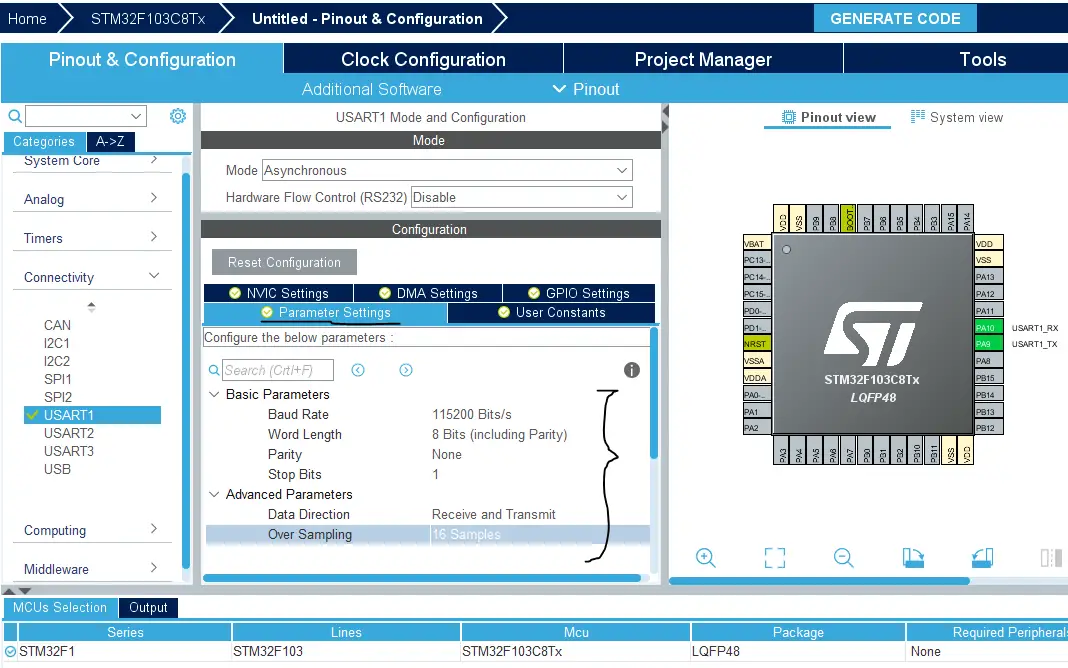
Step4: Choose The Desired Settings For UART (Baud Rate, Stop Bits, Parity, etc..)
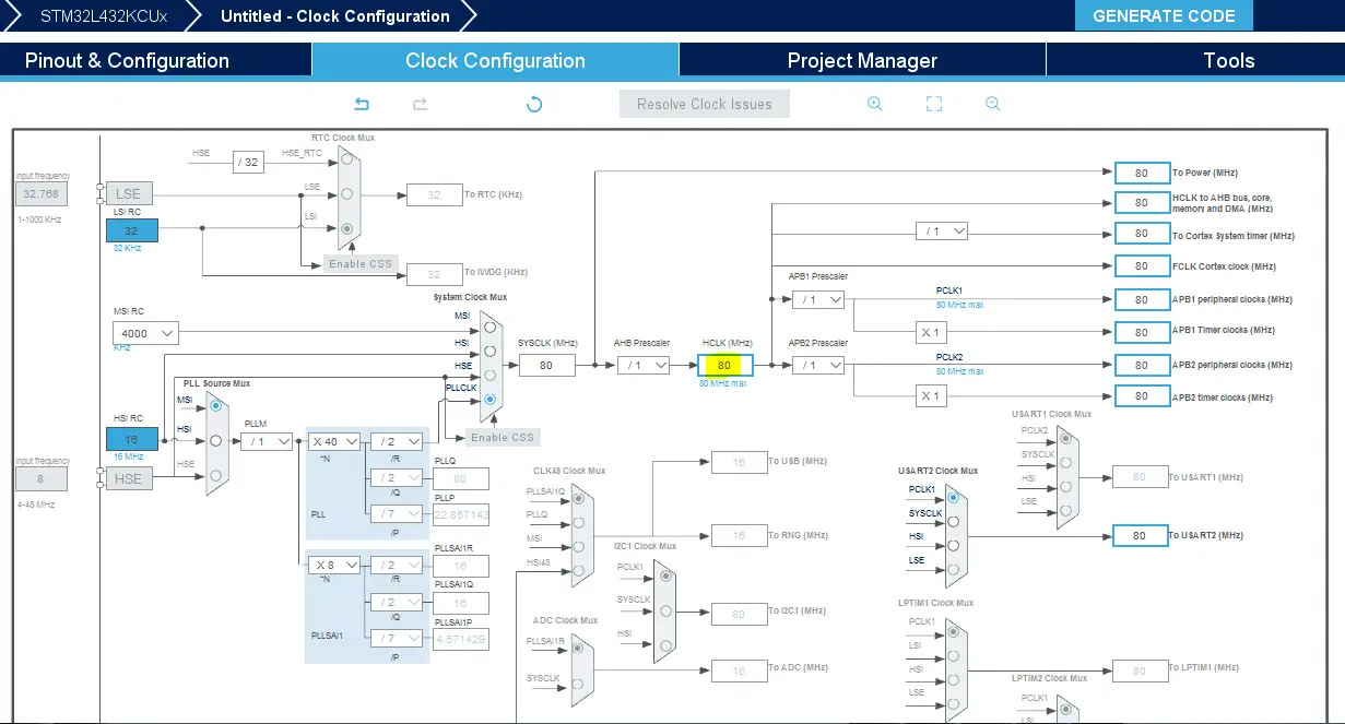
Step5: Go To The Clock Configuration & Set The System Clock To 80MHz
Step6: Generate The Initialization Code & Open The Project In CubeIDE
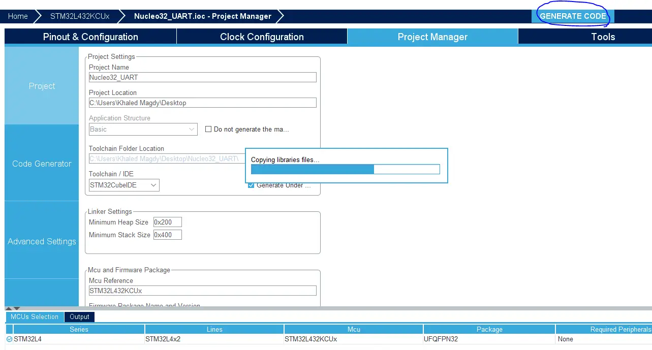
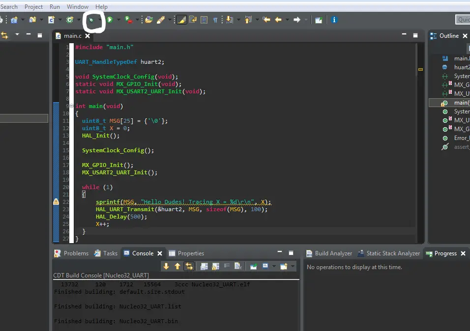
Step7: Write The Code For Your Project & Use HAL_UART_Transmit() To Print
|
1 2 3 4 5 6 7 8 9 10 11 12 13 14 15 16 17 18 19 20 21 22 23 24 25 26 27 28 |
#include "main.h" UART_HandleTypeDef huart2; void SystemClock_Config(void); static void MX_GPIO_Init(void); static void MX_USART2_UART_Init(void); int main(void) { uint8_t MSG[35] = {'\0'}; uint8_t X = 0; HAL_Init(); SystemClock_Config(); MX_GPIO_Init(); MX_USART2_UART_Init(); while (1) { sprintf(MSG, "Hello Dudes! Tracing X = %d\r\n", X); HAL_UART_Transmit(&huart2, MSG, sizeof(MSG), 100); HAL_Delay(500); X++; } } |
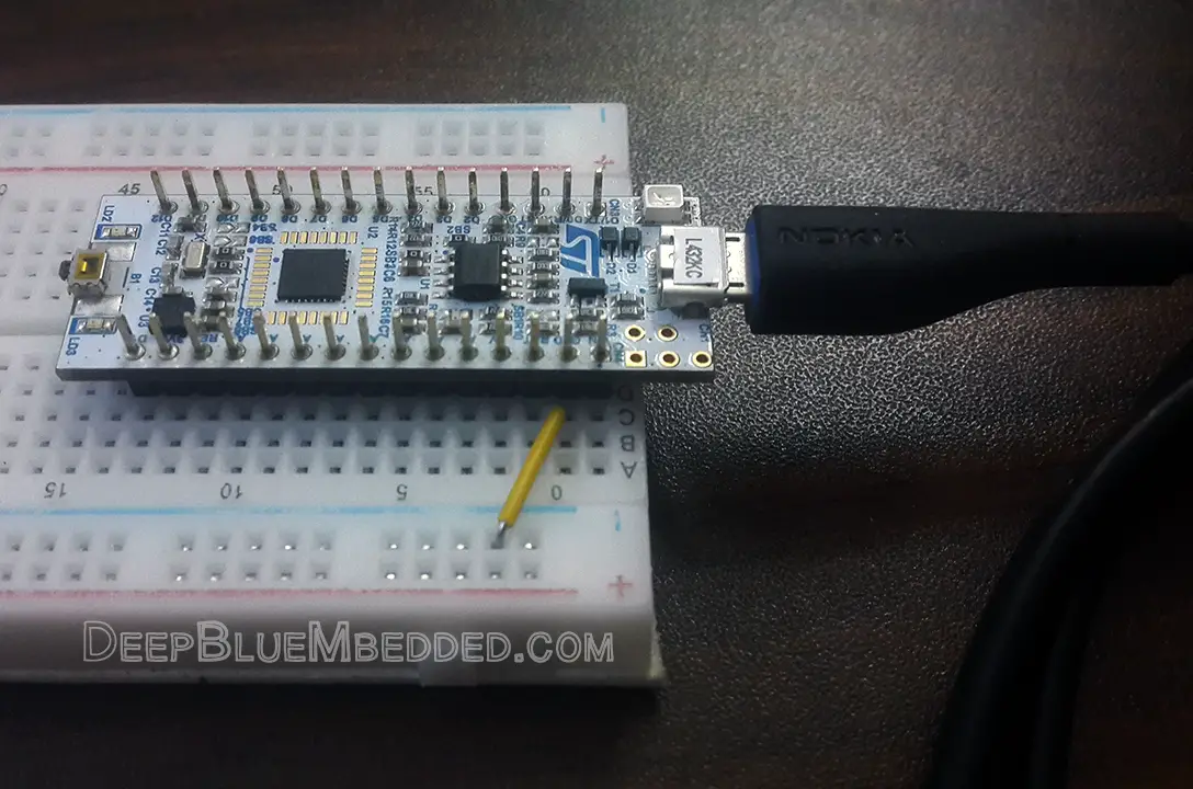
Step8: Build & Debug To Flash The Code
The Nice Part About It That The Same USB Cable Used To Flash The Code Is Now Being Used To Send The Serial Data As Well.
 |
 |
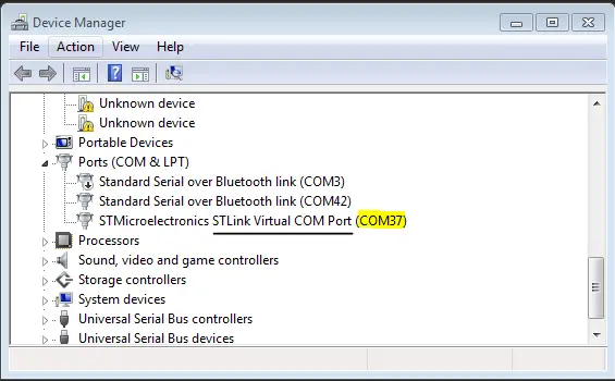
Step9: Go To The Device Manager & Check The ST-Link COM Port Num.
Step10: Open The Terminal From CubeIDE
Window > Show View > Console
In Console:
click on the NEW icon on its menu bar > Command Shell console > Connection type: Serial port > set Baud Rate & Connection Name > Encoding: UTF-8 > And Click OK!
Alternatively, You Can Use Any Terminal On Your PC (Like Tera Term, Arduino Serial Monitor, etc..)
STM32 Blue Pill Serial Port (USB-TTL)
| LAB Number | 5 |
| LAB Title | Serial Port Printing With Blue Pill + USB-TTL Converter |
Preface
The Blue Pill development board lacks an onboard ST-Link programmer/debugger, unlike Nucleo boards. That’s why we use the external USB ST-Link clone. And also it worth mentioning that the USB port on the blue pill board is connected to the STM32F103C8 hardware USB peripheral. Therefore, it can actually be used for debugging but you’ll develop a USB application for it and it’s a topic for a future tutorial.
However, the UART peripherals in the microcontroller can be used to send serial data to the PC serial COM port and display it on a terminal using a USB-TTL converter board. Hence, you’re not restricted to use a specific UART module (UART1, UART2, or UART3).
| Note | |||
|
The STM32F103C8 microcontrollers’ pins are not all 5v tolerant. Hence, you must be careful when receiving input signals from the USB-TTL converter. You can send a 3.3v signal from the MCU TX pin to the USB-TTL RX pin and still get the data identified absolutely fine. However, it won’t work the other way around without shifting the signal’s level. The TX from the USB-TTL can over-drive the MCU’s RX input pin. By checking the diagram below, you’ll notice that the pins for UART1 & UART3 are 5v tolerant while UART2 is not. |
|||
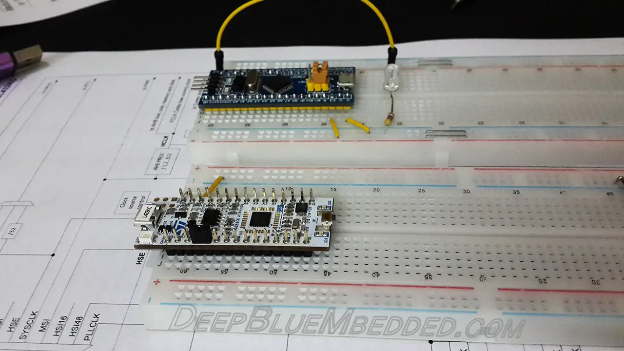
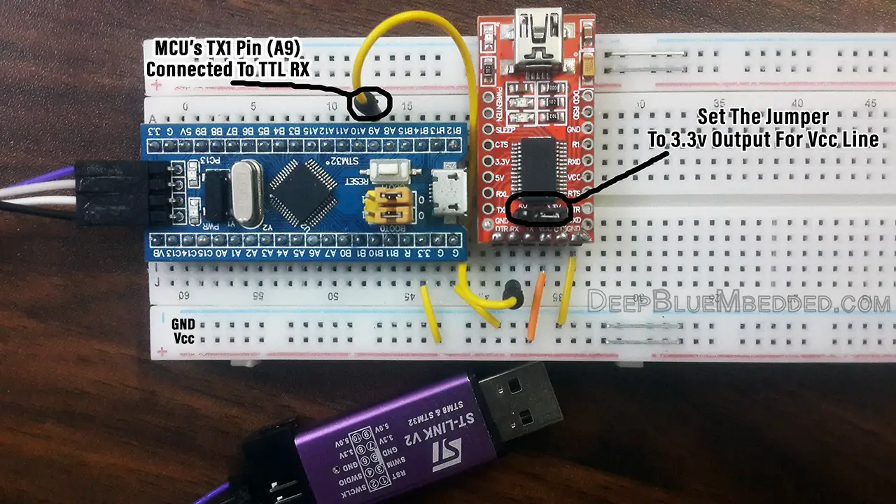
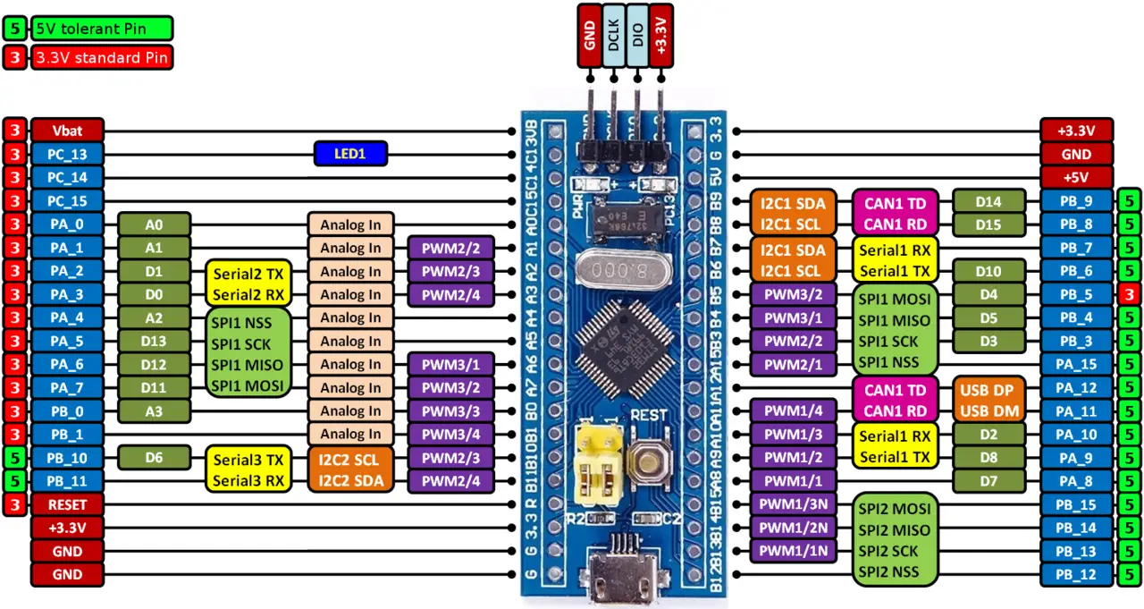 For this tutorial, we’ll use the UART1 module to send the serial data for debugging. Here is the connection diagram for this LAB. Note that we won’t send data from the terminal to the terminal, that’s why I didn’t connect that wire. If you need to send data to the microcontroller, you’ll have to connect it and configure the UART in your code so it handles data reception.
Serial Data Print (For Debugging) Project
Step1: Open CubeMX & Create New Project
Step2: Choose The Target MCU & Double-Click Its Name
Step3: Enable USART1 Module (Asynchronous Mode)
Step4: Choose The Desired Settings For UART (Baud Rate, Stop Bits, Parity, etc..)
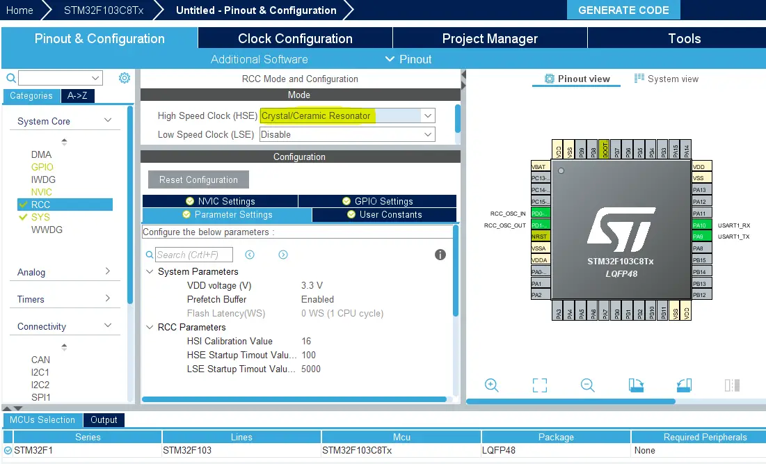
Step5: Goto The RCC Options Tab & Enable External Crystal
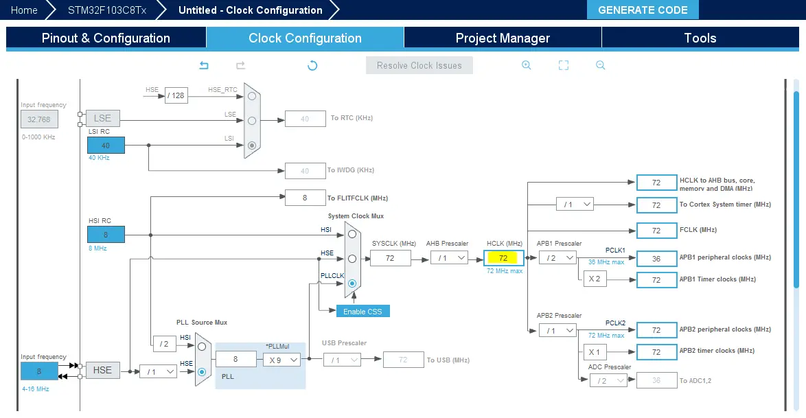
Step6: Go To The Clock Configuration & Set The System Clock To 72MHz
Step7: Generate The Initialization Code & Open The Project In CubeIDE
Step8: Write The Code For Your Project & Use HAL_UART_Transmit() To Print
|
1 2 3 4 5 6 7 8 9 10 11 12 13 14 15 16 17 18 19 20 21 22 23 24 25 26 |
#include "main.h" UART_HandleTypeDef huart1; void SystemClock_Config(void); static void MX_GPIO_Init(void); static void MX_USART1_UART_Init(void); int main(void) { uint8_t MSG[35] = {'\0'}; uint8_t X = 0; HAL_Init(); SystemClock_Config(); MX_GPIO_Init(); MX_USART1_UART_Init(); while (1) { sprintf(MSG, "Hello Dudes! Tracing X = %d\r\n", X); HAL_UART_Transmit(&huart1, MSG, sizeof(MSG), 100); HAL_Delay(500); X++; } } |
Step9: Build & Debug To Flash The Code
|
|
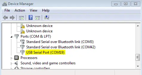
Step10: Go To The Device Manager & Check The USB-TTL COM Port Num.
Step11: Open The Terminal From CubeIDE
Window > Show View > Console
In Console:
click on the NEW icon on its menu bar > Command Shell console > Connection type: Serial port > set Baud Rate & Connection Name > Encoding: UTF-8 > And Click OK!
Alternatively, You Can Use Any Terminal On Your PC (Like Tera Term, Arduino Serial Monitor, etc..)
Don’t Forget To Support The Content By SHARING It On Socials Or Via Patreon!
| Previous Tutorial | Tutorial 10 | Next Tutorial | |||||
Hi,
I am really enjoying the Tutorials. I’ve shared them on LinkedIn, and I hope you keep doing them. IF you could do an I2C one that would be amazing, specifically making an STM32 a slave in a network would really help me and my projects.
I did notice two things though that seems to be an issue when I run the code on my STM32F103CT8(BluePill) using the ST-Link. The line
__HAL_AFIO_REMAP_SWJ_DISABLE(); stops the device immediately after programming with the ST-Link. Once commented out the code works fine and the debugger works too.
Another issue that seems to be with my set up is that the sprintf in this tutorial seems to overwrite the huart address space and resets the configuration registers to contain garbage. Once commenting out the UART transmission worked fine but not sure why the sprintf causes this. I ran your code as well, and it causes the same issues. It only ever happens after the sprintf statement.
All in all, still really helpful tutorials, please continue!
Thanks for the tutorials! They’re really helping.
I did notice one thing in the NUCLEO section here: when initializing MSG, it’s set to 25 characters instead of 35. This truncates the string when it’s assigned using the sprintf statement (omits the %d\r\n part), producing a not-as-expected console output without the incrementing X or line feed. The Blue Pill code has the correct size for MSG.
Hi Greg!
Oh. You’re definitely right! Thanks for the correction. I’ll have to edit this part very soon.